1
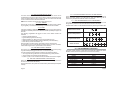
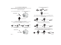
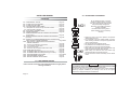
953
INSTALLATION AND
USE MANUAL
UK
GEMINI Technologies S.p.A.
Via Luigi Galvani 12 - 21020 Bodio Lomnago (VA) - Italia
Tel. +39 0332 943211 - Fax +39 0332 948080
www.gemini-alarm.com
ISO 9001 Certified Company
Made in Italy
AC 2743/UK - Rev.04 - 05/13
UK
CONTENTS
Page 2
Page 2
1.0 - PRELIMINARY ADVICE...........................................................
2.0 - USE AND MAINTENANCE......................................................
USER MANUAL
Page 3
3.0 - ALARM SYSTEM CONTROL DEVICES DESCRIPTION........
Page 3
3.1 - Remote control.......................................................................
Page 3
3.2 - Electronic key..........................................................................
Page 4
4.0 - SYSTEM OPERATION - BASIC CONFIGURATION...............
Page 4
4.1 - Arming.....................................................................................
Page 4
4.2 - Topcase/seat open warning signal..........................................
Page 4
4.3 - Pre-arm mode.........................................................................
Page 4
4.4 - Siren exclusion........................................................................
Page 5
4.5 - Motion sensor exclusion.........................................................
Page 5
4.6 - Full arming..............................................................................
Page 5
4.7 - Alarm.......................................................................................
Page 5
4.8 - Limiting acoustic signals.........................................................
Page 5
4.9 - Neutral time between alarm events........................................
Page 6
4.10 - System disarming without alarm memory.............................
Page 6
4.11 - System disarming with alarm memory...................................
Page 6
5.0 - PROGRAMMABLE FEATURES...............................................
Page 7
5.1 - Acoustic and optic signals.......................................................
Page 7
5.2 - Remote panic alarm................................................................
Page 7
5.3 - Shock sensor...................................................................... Page 7
5.4 - Passive arming.......................................................................
Page 7
5.5 - Anti-hijack feature...................................................................
Page 8
5.6 - Pre-alarm mode......................................................................
Page 8
5.7 - Self-rearming..........................................................................
Page 8
6.0 - SLEEP MODE..........................................................................
Page 8
7.0 - HAZARD FEATURE.................................................................
Page 9
8.0 - PIN-CODE OVERRIDE............................................................
Page 10
9.0 - PIN-CODE OVERRIDE EXAMPLE..........................................
Page11/12
10.0 - PIN-CODE CUSTOMIZATION...............................................
Page 13
11.0 - REPLACING REMOTE CONTROL BATTERIES................ Page 13
12.0 - WASTE ELECTRICAL AND ELECTRONIC EQUIPMENT Page 13
(WEEE) DIRECTIVE......................................................... Page 13
1.0 - PRELIMINARY ADVICE
Dear Customer,
Thank you for choosing this Gemini 953 alarm system designed and
manufactured in Italy specifically for two-wheeled vehicles.
The present manual includes information for all options available, you may
therefore find that some of the information does not apply.
Identify your model and follow the correct directions:
953: self-powered, supplied with 2 remote controls and 1 electronic key.
953.02: self-powered, supplied with 2 remote controls and snap-in LED indicator.
952: not self-powered, supplied with 2 remote controls and snap-in LED indicator.
Please read this manual carefully to familiarize yourself fully with the alarm
system features and operating procedures and do keep it handy for future
reference.
The following signal words and symbols are included to emplasize important
instructions and to alert user/installer to potential hazards:
! WARNING
Non-compliance to this instruction could result in serious damage to the
vehicle and to the alarm system.
CAUTION
Non-compliance to this instruction may cause serious damage or
operational failures to the alarm system.
2.0 - USE AND MAINTENANCE
Care should be taken to protect the electronic alarm system:
! Do not clean the alarm unit with water but use a damp cloth to wipe.
! Do not use voltages other than the one specified by the manufacturer.
! Protect the alarm from any direct water flow such as high-powered water
jets found in a car wash.
! WARNING
Gemini Technologies S.p.A. will not be held responsible for any damage
caused by improper use.
Page 1
Page 2
USER MANUAL
3.0 - ALARM SYSTEM CONTROL DEVICES
Electronic Key Receptacle Positioning
Electronic key
The remote controls and electronic key are used to operate the alarm system.
A PIN-CODE can also be used to emergency override the system should the
remote control be lost or inoperative. Override PIN CODE is entered by
means of ignition key (see chapters 8 and 9).
3.1 - REMOTE CONTROL
The remote control has 2 different function buttons each of which
corresponds to a control signal that activates a selected action according to
the operational condition and alarm configuration.
The textured button is for arming/disarming the alarm while the smooth button
is used to exclude or trigger the siren.
The remote control has a low charge battery indicator that gives you early
warning to avoid malfunctioning. When the batteries are fully charged, the
LED will show a steady light at the press of a button. If the batteries are low,
the LED will start blinking when the button is pressed.
Button 1: ! Alarm system arming/disarming
! Anti-hijack feature activation
! Hazard lights feature activation
LED
indicator
Button 1
Button 2: ! Anti-hijack feature activation
! Panic siren activation/deactivation
! Siren silencing during alarm conditions
! Siren ON/OFF when arming
! Motion sensor programming and setting
Button 2
3.2 - ELECTRONIC KEY
The electronic key is a simplified remote control. In emergency situations (ex.
in case of remote control failure), it can be used to arm/disarm the alarm or
activate/deactivate the anti-hijack feature (if enabled).
To use the electronic key, simply touch it to its receptacle.
The touch receptacle incorporates a LED warning light that serves as both a
system status indicator and a visual theft deterrent.
Page 3
Electronic key
4.0 - SYSTEM OPERATION - BASIC CONFIGURATION
4.1 - ARMING
Press remote control button 1 or insert the electronic key into its receptacle to
arm the alarm system. Arming is confirmed by a flash of the turn indicators and
2 short beeps. The LED turns ON steady.
4.2 - TOPCASE/SEAT OPEN WARNING SIGNAL
If, during the arming process, the topcase or seat are open or incorrectly closed, a
low-tone signal (boop) will sound after the arming confirmation tones.
The alarm will arm but an alarm condition will be triggered after the pre-arm mode.
4.3 - PRE-ARM MODE
After the arming confirmation signals, the LED turns ON steady to indicate the system
is in pre-arm mode; it will become fully active after 20”.
Engine immobilization and optional module inputs are active during the pre-arm mode.
4.4 - SIREN EXCLUSION
During the first 4” of the pre-arm mode, the alarm siren can be excluded by
pressing remote control button 2. The turn indicators will give a quick flash to
confirm the siren has been excluded.
CAUTION
If the siren is excluded (Mute alarm) only the turn indicators will flash
during an alarm event. Engine immobilization will remain enabled.
NB: Siren exclusion is bound to each single arming cycle.
Page 4
4.5 - MOTION SENSOR EXCLUSION
The alarm built-in sensor to detect tilt, motion or a sudden shock can be
excluded during the first 4” of the pre-arm time by inserting the electronic key
into its receptacle after the alarm system is armed. The status LED will blink
once to confirm the sensor has been excluded.
NB: Sensor exclusion is bound to each single arming cycle.
4.6 - FULL ARMING
After the 20” pre-arm time, the alarm system is fully armed and ready to detect
any irregularity. The LED will start blinking to confirm the armed condition.
4.7 - ALARM
If an alarm condition is detected during the armed state, the siren will sound, the
LED will turn ON steady and the turn indicators will flash repeatedly for approx. 30
seconds.
The following irregularities will trigger an alarm if the relative sensors are
activated:
! Cable cut tamper detection;
! Ignition attempt (positive under key);
! Motion detection (ex. lifting, towing, forcing the steering lock);
! Seat/topcase unauthorized access (if protected by a contact switch );
! Panic siren ( remote control button 2).
When the alarm condition ceases, the system returns in armed mode.
To interrupt the siren and the flashing indicators during an alarm condition,
without disarming the alarm, press remote control button 2.
4.8 - LIMITING ACOUSTIC SIGNALS
Each alarm event caused by unauthorized movement, seat/topcase opening
or ignition attempt will trigger the siren for 7 consecutive cycles.
The siren will then be automatically excluded for the following reasons:
! To comply with the regulations in force aimed at limiting noise pollution;
! To save power and maximize vehicle battery life;
! If, after 7 cycles, no one checks the vehicle, it is useless to have it sound again.
4.9 - NEUTRAL TIME BETWEEN ALARM EVENTS
When the alarm cycle is over, any further alarm event will be ignored for 5
seconds; the LED will be ON steady.
During neutral time, the system can be disarmed by PIN CODE (see chapters
8 and 9) .
Page 5
4.10 - SYSTEM DISARMING WITHOUT ALARM MEMORY
Press remote control button 1 or insert the electronic key in its receptacle to
disarm the alarm system. The LED will turn OFF and disarming will be
confirmed by 3 beeps and 3 flashes of the turn indicators.
4.11 - SYSTEM DISARMING WITH ALARM MEMORY
If an alarm event has occurred while you were away from your vehicle, it will
be signalled by 2 flashes of the turn indicators and 2 low-tone beeps.
The last cause of alarm can be identified as follows by observing the status LED:
Motion sensor alarm:
Ignition attempt alarm:
Topcase/seat alarm:
Cable cut alarm:
5.0 - PROGRAMMABLE FEATURES
The alarm system is factory preset with some features enabled and others
disabled. The shock sensor is preset to be at minimum sensitivity.
Factory setting
Feature
Acoustic signals
Panic siren
Motion sensor
Passive arming
Anti-hijack
Pre-alarm
Self-rearming
Status
Enabled
Enabled
Enabled
Disabled
Disabled
Disabled
Disabled
Page 6
5.1 - ACOUSTIC AND OPTICAL SIGNALS
Optical signals (turn indicators and status LED) and acoustic signals (siren)
indicate arming/disarming, alarm memory, system programming and learning
of new devices. Acoustic signals can be disabled.
The system will cause the motorcycle engine to be cut off 20” after activation.
Two seconds later the siren will go off continuously for 1 minute and the turn
indicators will start blinking repeatedly until the anti-hijack is disabled.
To deativate anti-hijack insert the electronic key in its receptacle.
5.2 - REMOTE PANIC SIREN
For use in emergency situations. Panic alarms can be triggered as many times
as necessary but at least 5” must elapse between two consecutive alarms.
Pressing button 2 will immediately activate the siren and the turn indicators for
approx. 30 seconds. To deactivate the panic siren simply press button 2 again.
The panic siren can be activated with either an armed or disarmed system.
5.6 - PRE-ALARM MODE
During an alarm event, the siren will only go off for 2.5 seconds (rather than for
the standard 30 sec.). The pre-alarm mode is only activated for the first 3 alarm
events, from the 4th detection the siren will sound for the full 30 sec. sequence.
The pre-alarm feature helps preserve battery life and reduce noise pollution.
Alarm cycles will be reset every time the alarm is disarmed or whenever the
panic alarm is activated.
5.3 - SHOCK SENSOR
The built-in sensor with adjustable sensitivity will trigger an alarm whenever it
detects tilt, motion or a sudden shock to the vehicle.
5.4 - PASSIVE ARMING
The system can be programmed to automatically arm every time ignition is
turned OFF, making sure the vehicle won’t be left unprotected.
When ignition is turned OFF the turn indicators will flash once, the status LED
twice and the siren will chirp 2 times to indicate the system is in pre-arm mode.
The system fully arms (passive arming) 35” after ignition is turned OFF. A flash
of the turn indicators and 2 beeps will confirm the system is armed. The LED
will turn ON steady.
Lifting the seat or opening the topcase (if protected by a contact switch) during
the 35” pre-arming time will cause the procedure to interrupt; it will resume
once the seat or topcase are closed.
To interrupt passive arming, turn ignition ON within 35” of turning it OFF.
5.5 - ANTI-HIJACK FEATURE
This feature allows the user to remotely switch off the motorcycle engine in
case of a hijack attempt.
To activate the anti-hijack while the engine is running, either:
! Press remote control button1, or
! Press remote control button 2, or
! Insert the electronic key in its receptacle.
Two quick flashes of the turn indicators will confirm activation and the LED will
turn ON steady.
CAUTION
Once the anti-hijack is activated, the remote controls will be inoperative.
Page 7
5.7 - SELF-REARMING
When the system is armed and then accidentally disarmed, the system will
automatically rearm 35” after it has been unintentionally disarmed. The
standard acoustic and optical signals will confirm activation.
6.0 - SLEEP MODE
If the vehicle will be sitting idle for a period of time, the alarm can be switched
off (sleep mode) to preserve battery life.
To activate the Sleep mode feature, proceed as follows:
! Turn ignition key “ON”; the LED will light up for approx. 1”.
! Within 4” of the LED flash, insert the electronic key into its receptable; a
beep will confirm the alarm system has been turned OFF.
! Turn ignition key “OFF”.
! To re-arm the alarm system, turn ignition key “ON” and then “OFF”.
7.0 - HAZARD FEATURE
To make the turn indicators flash as hazard warning lights proceed as follows:
!
!
!
!
!
Turn ignition key “OFF”.
Then turn ignition key “ON”; the LED will light up for approx. 1 second.
While the LED is ON, press remote control button 1.
Turn ignition key “OFF”; the turn indicators will start flashing.
To disable flashing, turn ignition key “ON” (and eventually “OFF”) or arm
the system.
Page 8
8.0 - PIN-CODE OVERRIDE
9.0 - PIN-CODE OVERRIDE EXAMPLE
If you cannot disarm the system from the remote control or with the electronic
key (remotes are lost or broken or batteries are flat), you will be able to disarm
the system by using the PIN override procedure. Override PIN code is entered
by means of ignition key.
For security reasons, we recommend that you change the PIN code from the
factory default setting 1-1-1-1 (see chapter 10). It can be set to any number
between 1 and 9.
To help you understand the override procedure by PIN-CODE, here below is a
step-by-step example entering PIN-CODE 2-3-4-1.
Arm the system, wait for the end of pre-arm time and then generate an
alarm condition.
To override the system:
Key “ON”
Key “OFF”
! Trigger an alarm condition; as soon as the alarm ceases, the status LED will
turn ON steady for approx. 5”.
! While the LED is ON steady, turn ignition key “ON” and then “OFF”.
CAUTION
If the ignition key stays in the “ON” position for more than 5”, the system
will interpret the situation as a theft attempt and therefore trigger another
alarm.
! The status LED will turn OFF to confirm the system is in disarm mode.
! 4” after the LED has turned OFF, it will start flashing a series of 9 blinks.
! At the number of flashes equal to the PIN CODE 1st digit, turn ignition key
ON and OFF. This will confirm the entered digit.
! After 4”, the LED will flash again 9 times.
! When the number of flashes is equal to the PIN-CODE 2nd digit, turn
ignition key ON and OFF.
! Repeat the above steps for the remaining two digits.
! If the code has been entered correctly, the system will disarm and indicate
the last cause of alarm as indicated in paragraph 4.11 ”System disarming
with alarm memory” .
CAUTION
If the LED blinks more than 9 times, the procedure will be invalidated and
considered a theft attempt.
Alarm condition
When the alarm condition ceases, the status LED turns ON steady for
approx. 5”. While the LED is ON, turn ignition key “ON” and “OFF”; the
LED will turn OFF to confirm the system is in PIN CODE disarm mode.
LED steady
ON for
approx. 5”
Key “ON”
The LED will start blinking 4” after turning OFF. Count the flashes and turn
ignition key “ON” and “OFF” when the number of flashes
equals the PIN-CODE 1st digit (in this case ‘2’).
After 4” the LED will start blinking again.
Count 3 blinks (3rd digit) and turn ignition key “ON” and “OFF”.
4 sec.
4 sec.
1st digit: “2”
“ON” “OFF”
2nd digit: “3”
“ON” “OFF”
After another 4” the LED will blink again. Turn ignition key “ON” and “OFF”
when the number of flashes equals the other 2 digits (4 and 1).
4 sec.
4 sec.
rd
3 digit: “4”
Page 9
LED OFF to
confirm override
mode
Key “OFF”
“ON” “OFF”
4th digit:“1” “ON” “OFF”
If the PIN CODE has been entered correctly, the alarm system will disarm
and indicate the last cause of alarm.
Page 10
Press both buttons at the same time.
The LED will turn OFF.
10.0 - PIN-CODE CUSTOMIZATION
Here below is a step-by-step example showing how to customize the PINCODE. In this case the selected PIN-CODE is 2-3-4-1.
LED
OFF
Disarm the alarm system.
Ground the BROWN/GREEN wire.
Open the seat (if protected by a
contact switch).
Turn ignition key “OFF”
BROWN/GREEN
NEGATIVE
After 4 seconds, the LED will flash 9 times. Count the flashes and turn
ignition key “ON” and “OFF” when the number of flashes equals the new
PIN-CODE 1st digit.
Turn ignition key “ON”
Key “ON”
The status LED will light up for 0.5 seconds.
While the LED is ON, simultaneously press both buttons on the remote
control.
The alarm will beep twice and the LED will turn ON steady.
Boop
Boop
0.5
sec.
Remove the BROWN-GREEN wire
from negative.
BROWN-GREEN
NEGATIVE
Page 11
After 4”, the LED will flash again 9 times.
Repeat the above steps to enter the 2nd digit.
Steady
ON
Close the seat (if protected by a
contact switch).
LED
OFF
Key “OFF”
Key “ON”
LED
OFF
Key “OFF”
Repeat the above steps to enter the last two digits.
When the 4th digit is entered, the system automatically exits the
procedure. Two low tone acoustic signals and a high tone signal will
confirm the code has been entered successfully.
Last
digit
Key “ON”
Key “OFF”
Boop
Boop
Beep
Page 12
R&TTE Declaration of Conformity
Doc ref. No. 2010-01
11.0 - REPLACING REMOTE CONTROL BATTERIES
The remote control operates using alkaline batteries. When the batteries are
too weak, replace them as follows:
We, the undersigned,
Company
Address, City
Country
Phone number
Fax number
BATTERIES
Separate the
remote halves
taking care not to
damage the
internal circuit.
Declare under our sole responsibility that the following eqipment:
Remove the
discharged batteries
and insert the new
ones taking care not to
invert the battery
polarity.
Close the
remote halves
and make sure it
works properly.
! WARNING
Use only CR1616 batteries.
Different type batteries can seriously damage the remote control unit.
Discard used batteries properly in special dedicated containers.
12.0 - WASTE ELECTRICAL AND ELECTRONIC EQUIPMENT
(WEEE) DIRECTIVE
The present device does not fall within the scope of Directive 2002/96/EC on
Waste Electrical and Electronic Equipment (WEEE) as specified in art. 2.1 of
L.D. no. 151 of 25/07/2005.
13.0 - TECHNICAL SPECIFICATIONS
Power supply
Supply voltage range
Current absorption @ 12Vdc
Current absorption in sleep-mode
Siren sound level
Relay capacity
Page 13
GEMINI TECHNOLOGIES S.p.A
Via Luigi Galvani 12, 21020 Bodio Lomnago (VA)
Italy
+39 0332 943211
+39 0332 948080
12 Vdc
9Vdc-15Vdc
<0,7mA (system armed and
LED flashing)
< 1µA
118 dBA @1 meter
8A
Product description /
Intended use
EU / EFTA member states
intended for use
Member states with restrictive use
Manufacturer
Brand name
Type / Model
Remote control at 433,92 Mhz for vehicle
alarm system
EU: all members
EFTA: all members
None
GEMINI TECHNOLOGIES S.p.A.
GEMINI
7208E and 7218E
Is tested to and conforms with the essential requirements as mentioned in Art. 3.1 (a) for
protection of Health and Safety of the user and any other person and in Art. 3.1 (b) for
Elecromagnetic Compatibility, as included in the following standards:
Art. of Directive
3.1 (a) Health
3.1 (a) Safety
3.1 (b) EMC
3.1 (b) EMC
Standard
EN 50371
EN 60950-1 +A11
EN 301 489-3
EN 301 489-1
Date of issue of the standard
2002
2006; 2009
V2.1.1 (2009-05)
V1.8.1 (2008-04)
And is tested to and conforms to Art. 3.2, with the essential radio test suites so that it
effectively uses the frequency spectrum allocated to terrestrial/space radio
communication and orbital resources so to as avoid harmful interference, as included in
following standards:
Art. of Directive
3.2 Spectrum
Standard
EN300 220-2
Date of issue of the standard
V2.3.1 (2010-02)
And therefore complies with the essential requirements and provisions of the Directive
199/5/EC of the European Parliament and of the council of March 9, 1999 on Radio
Equipment and Telecommunications Terminal Equipment and the mutual recognition of
theis conformity and with the provisions of Annex II.
TCF reference nr.
Date
Name and position
TCF_ 7208E/7218E
August 23, 2010
Andrea Rossi, General
INSTALLER MANUAL
2.0 - ALARM UNIT POSITIONING
CONTENTS
1.0 - PRELIMINARY ADVICE......................................................Page 15
2.0 - ALARM UNIT POSITIONING..............................................Page 16
3.0 - ALARM UNIT SEALING......................................................Page 17
4.0 - ACCESSORIES POSITIONING..........................................Page 18
4.1 - Receptacle for electronic key and LED indicator..............Page 18
4.2 - Contact switch (optional)...................................................Page 18
5.0 - ELECTRICAL CONNECTIONS..........................................Page 19
6.0 - WIRING DIAGRAM.............................................................Page 20
7.0 - ENGINE IMMOBILIZATION CONNECTION DIAGRAM
(ground wire).......................................................................Page 21
8.0 - ENGINE IMMOBILIZATION CONNECTION DIAGRAM
(cut wire)...............................................................................
Page 22
9.0 - EXAMPLE OF ENGINE IMMOBILIZATION CONNECTION
WITH SPECIFIC WIRING HARNESS....................................Page 23/24
10.0 - ELECTRICAL CONNECTIONS WITH SPECIFIC
WIRING HARNESS............................................................Page 25
10.1 - Engine immobilization connections..................................Page 25
10.2 - Turn indicator connections...............................................Page 25
10.3 - Ground connection..........................................................Page 25
10.4 - Electronic key receptacle with built-in LED......................Page 25
11.0 - DIODE INSTALLATION.....................................................Page 26
12.0 - LEARNING NEW DEVICES (with ground wire)................Page 27
13.0 - LEARNING NEW DEVICES (without ground wire)...........Page 28
14.0 - PROGRAMMABLE FEATURES.......................................Page 29/30
15.0 - PROGRAMMING EXAMPLE
Page 31
16.0 - MOTION SENSOR ADJUSTMENT
Page 32
NO!
OK!
Do not install the alarm unit in this
position as water ingress over time
may seep through the rubber sheath
and permanently damage the
electronic circuit making the alarm
system unreliable.
Eventual malfunctioning due to
water infiltration is not covered by
warranty.
! Fitting the control unit in this position, will prevent
water entering the unit.
! It is important to give the rubber sheath a ‘gooseneck’ bending as shown in the picture opposite and
secure with a tie wrap.
! Do not expose to atmospheric agents.
! Pay attention not to muffle the siren speaker.
! Secure away from moving mechanical parts.
! Keep away from devices that could generate high
frequency electromagnetic disturbances.
! Keep away from devices that could reach high
temperatures when the vehicle is in use.
! Do not secure the control unit directly on the vehicle
frame.
1.0 - PRELIMINARY ADVICE
Please read all instructions and understand them thoroughly before
starting installation.
Page 15
CAUTION
If a jet wash is used to clean the vehicle, protect the alarm unit from water
splashes and be careful not to expose it to high pressure jets.
The warranty will not cover damages to the system due to water infiltrations
caused by improper installation, jet washing or the use of non original
accessories, not approved by the manufacturer.
Page 16
3.0 - ALARM UNIT SEALING
To seal the alarm, position the
rubber cap over the external edge
of the alarm housing as shown
below.
Pull the plastic rectangular flange
over the rubber cap and secure
with the supplied screws.
Do not over tighten the screws.
4.0 - ACCESSORIES POSITIONING
4.1 - RECEPTACLE FOR ELECTRONIC KEY AND LED INDICATOR
The receptacle with built-in LED (or the LED) must be installed where it can
readily be seen and accessed by the user. The LED warning light serves as
both a system status indicator and a visual theft deterrent
Always check for rear clearance before drilling. If drilling a hole in the plastic
dash, check the position of the handlebars with the steering lock engaged.
Make sure the LED will not be covered by the handlebars when the vehicle is
parked.
Drill size for the electronic key receptacle: 13mm.
Drill size for the LED indicator: 10mm.
Electronic key
Electronic key
Alarm unit sealed
4.2 - CONTACT SWITCH (OPTIONAL)
A contact switch can be fitted to protect the seat or topcase. It must be installed
in such a way as to detect the opening of the seat/topcase without being
accessible from the outside. The trigger threshold must be carefully set to
avoid false alarms.
Do not ground the switch terminal to the vehicle frame as it might not be
connected to the battery negative pole. Connect to a cable that provides
continuous ground such as the indicator lamp negative lead.
NB: If no contact switch is fitted, the GREEN/BROWN wire will remain free for
other possible uses.
Page 17
Page 18
6.0 - WIRING DIAGRAM
5.0 - ELECTRICAL CONNECTIONS
CAUTION
The tables below refer to the standard wiring harness (KITCA 417).
For a complete list of model-specific wiring harnesses, please visit:
www.gemini-alarm.com (private area).
Pos.
Wire colour
Wire function
-1-2-3-4-5-6-7-8-9- 10 - 11 - 12 - 13 - 14 - 15 - 16 -
Brown
Brown
White-Violet
Green-Brown
----Yellow
Black
Green
Grey
White
White-Grey
Orange
Red
Orange
Black
Electronic key ground
Ground
Device learning push-button input
Contact switch input
Not applicable
Not applicable
Ignition
LED negative output
Electronic key input
Engine cut (N.C.)
Engine cut (Com.)
Engine cut (N.O.)
Turn indicators
Positive
Turn indicators
Antenna
16 15 14 13 12 11 10 9
8 7 6 5 4 3 2 1
Receptacle
with built-in LED
Orange
Turn indicator
connections
Connection
White
Connect to ignition key switch cut end
Grey
15A
Orange
15A
Seat/topcase
contact switch
Installation
recommended
Green/Brown
ENGINE CUT-OFF - cut wire
Wire colour
Electronic key
Ground
Engine cut-off
Optional fuse (recommended)
10A
Connect to vehicle electric system cut wire
Red
Brown
ENGINE CUT-OFF - grounded wire
Wire colour
White
White/Grey
Page 19
Connection
Connect to vehicle continuous negative
(do not connect to vehicle frame)
Connect to the cable end which, if earthed, will cut
the engine
Battery
12 Volt
Grey
White/Grey
White
Vehicle
battery
Green/Black
Brown
Yellow
Ignition key
Page 20
7.0 - ENGINE IMMOBILIZATION CONNECTION DIAGRAM
ENGINE CUT-OFF by GROUNDING A WIRE
8.0 - ENGINE IMMOBILIZATION CONNECTION DIAGRAM
ENGINE CUT-OFF by CUTTING A WIRE
For most small
two-stroke motorcycle engines
For most large
four-stroke motorcycle engines
White
White
White/Grey
Ground
Grey
Ignition key
Engine immobilization wire
Ignition key
Engine immobilization wire
Cut
To vehicle engine
Page 21
To vehicle engine
Page 22
9.0 - EXAMPLE OF ENGINE IMMOBILIZATION CONNECTION
WITH SPECIFIC WIRING HARNESS
9.0 - EXAMPLE OF ENGINE IMMOBILIZATION CONNECTION
WITH SPECIFIC WIRING HARNESS
3
1
Ignition key
Ignition key
Alarm unit
Vehicle wiring harness
before fitting the
specific wiring harness
Engine
Engine
2
Ignition key
Disconnect the ignition
switch connector from
the vehicle wiring harness
Engine
Page 23
Plug the alarm
harness connector
into the ignition
switch connector
Plug the alarm
harness connector
into the vehicle
wiring harness
connector
4
Ignition key
Alarm unit
Vehicle wiring
harness connected
to the alarm
wiring harness
Engine
Page 24
10.0 - ELECTRICAL CONNECTIONS WITH SPECIFIC
WIRING HARNESS
After selecting the appropriate position for the alarm system and accessories
(electronic key receptacle, seat/topcase contact switch), proceed with the
electrical connections.
Pay special attention to the following instructions in order to ensure proper
electrical connections and refer to the relative drawings.
10.1 - ENGINE IMMOBILIZATION CONNECTIONS
! Disconnect the ignition switch connector (or the factory installed device for
engine immobilization) from the vehicle main wiring harness connector (fig.2).
! Insert the alarm harness connectors as follows: one into the ignition switch
connector (or the factory installed immobilization device) and the other into
the vehicle main wiring harness (fig.3).
! Connectors cannot be inverted because they are polarized.
10.2 - TURN INDICATOR CONNECTIONS
! Connect the alarm harness wires to the the same color vehicle wires that
provide a positive feed to the turn indicator lamps.
10.3 - GROUND CONNECTION (WHEN NOT AVAILABLE ON THE
IGNITION SWITCH)
! If the vehicle ignition switch does not have a ground wire (ex. four-stroke
engine vehicles) the alarm ground wire must be connected to a vehicle
ground point (ex. turn indicator negative lead).
! Do not connect the alarm ground cable to the vehicle frame.
10.4 - ELECTRONIC KEY RECEPTACLE WITH BUILT-IN LED
Connect the receptacle 2-way BLACK connectors to the relative alarm unit 2-way
BLACK connectors.
Wires inside the receptacle connectors are RED and BLACK and they are
BROWN and GREEN in the alarm unit connectors.
11.0 - DIODE INSTALLATION
Check if a diode needs to be installed on the vehicle:
! Activate one of the turn indicators, turn ignition OFF and arm the alarm.
! If the instrument panel comes on when the turn indicators are activated, a
diode needs to be installed (see diagram below).
! If the instrument panel does not light up, do not insert a diode.
CAUTION
Adiode is not really necessary if, when the alarm is armed, the instrument
panel comes on.
No damage will be incurred to the vehicle in case a diode is not fitted.
Vehicle wiring harness
After
Before
Turn indicator relay
Turn indicator relay
WHITE wire
Cut
Diode inserted
in the vehicle
wiring harness
BLACK wire
Live feed
to the indicator
Vehicle original
wiring
Vehicle original
wiring
Page 25
Page 26
12.0 - LEARNING NEW DEVICES
13.0 - LEARNING NEW DEVICES
(With BROWN/GREEN WIRE GROUND CONNECTION)
(Without BROWN/GREEN WIRE GROUND CONNECTION)
The alarm is supplied with 2 remote controls and 1 electronic key but extra
optional devices can be added.
The alarm is supplied with 2 remote controls and 1 electronic key but extra
optional devices can be added.
To learn a new device, proceed as follows:
To learn a new device, proceed as follows:
! Make sure passive arming feature is disabled.
! Disarm the alarm system via remote control or electronic key.
! Lift the seat or open the topcase or, if no contact switch is fitted, ground the
BROWN-GREEN wire.
! Connect the learning button to the relative connector, YELLOW or yellow
sheathed.
! Press and hold the learning button.
! Turn ignition key “ON”.
! Two flashes of the turn indicators and two beeps, a high and a low tone, will
confirm the system is in learn mode.
! Release the button.
! Press one of the buttons on the remote control to be learned or insert the
electronic key in its receptacle.
! A flash of the turn indicators and a beep will indicate the new device has
been learned.
! If other devices need to be learned, press and release the learning button
once again and then press the remote control button or insert the electronic
key in its receptacle.
! Turn ignition key “OFF” to exit the procedure, a low-tone beep and a single
flash of the direction indicators will confirm the end of the procedure.
! Close the seat or topcase or remove the BROWN/GREEN wire from
ground.
Make sure passive arming feauture is disabled.
! Disarm the alarm system via remote control or electronic key.
! Turn ignition key “ON”.
! The status LED will turn ON for 1”.
! While the LED is ON, press both buttons on the remote control
simultaneously or insert the electronic key into its receptacle.
! Two flashes of the turn indicators and two beeps, a high and a low tone, will
confirm the system is in learn mode.
! Press one of the buttons on the remote control to be learned or insert the
electronic key in its receptacle.
! If other devices need to be learned, wait 2” and then press one of the
buttons on the remote control or insert the electronic key in its receptacle.
! Turn ignition key “OFF” to exit the procedure.
! A low-tone beep and a flash of the turn indicators will confirm the end of the
procedure.
CAUTION
Alarm memory will only store 8 devices.
Saving an extra device will automtically delete the first one.
CAUTION
Alarm memory will only store 8 devices.
Saving an extra device will automtically delete the first one.
Page 27
Page 28
14.0 - PROGRAMMABLE FEATURES
To either enable or disable one of the programmable features proceed as shown
below:
After pressing both buttons simultaneously (step 4), program the features
according to your needs.
TO ENABLE
TO DISABLE
Press button 1
Press button 2
NB: Remember to ALWAYS arm and disarm the alarm before programming.
1
With the alarm system disarmed, lift the
seat or open the topcase (if they are
protected by a contact switch) otherwise
ground the GREEN/BROWN wire.
Remove from ground after
programming.
ACOUSTIC SIGNALS
(enabled by Gemini)
3
Button N.1: ENABLE
MOTION SENSOR
(enabled by Gemini)
Button N.1: ENABLE
PASSIVE ARMING
(disabled by Gemini)
Button N.1: ENABLE
ANTI-HIJACK
(disabled by Gemini)
Button N.1: ENABLE
PRE-ALARM
(disabled by GEMINI)
Button N.1: ENABLE
SELF-REARMING
(Disabled by Gemini)
Button N.1: ENABLE
The LED will light up for approx. 1”.
4
While the LED is ON, simultaneously press
the 2 buttons on the remote control.
Two beeps (a low and a high tone beep) will
confirm the system is in programming mode.
The LED will light up steady .
Button N.2: DISABLE
PANIC SIREN
(enabled by Gemini)
2
Turn ignition key “ON”.
Button N.1: ENABLE
Button N.2: DISABLE
Button N.2: DISABLE
Button N.2: DISABLE
Button N.2: DISABLE
Button N.2: DISABLE
Button N.2: DISABLE
EXIT PROGRAMMING
Page 29
Page 30
15.0 - PROGRAMMING EXAMPLE
16.0 - MOTION SENSOR ADJUSTEMENT
To help you understand the programming procedure, here below is an
example showing how to activate the acoustic signals, the panic alarm, the
shock sensor and the pre-alarm features.
Keep in mind that, at every button press, the system automatically scrolls to
the next feature.
! With the system disarmed, lift the seat or topcase (if protected by a
contact switch) otherwise ground the BROWN/GREEN wire.
! Turn ignition key “ON”; the LED will turn ON for 1”.
! While the LED is ON, simultaneously press the two buttons on the remote
control. Two beeps will confirm the system is in programming mode. The
LED will light up steady.
! Press button 1; a high tone beep will confirm acoustic signals have been
enabled.
! Press button 1; a high tone beep will confirm the panic siren has been
enabled.
! Press button 1; a high tone beep will confirm the motion sensor has been
enabled.
! Press button 2; a low tone beep will indicate passive arming has been
disabled.
! Press button 2; a low tone beep will indicate the anti-hijack feature has
been disabled.
! Press button 1; a high tone beep will confirm pre-alarm has been
enabled.
! Press button 2; a low tone beep will confirm self-rearming has been
disabled.
! When the last feature has been enabled or disabled, the system
automatically exits the programming procedure. Two low tone beeps
followed by a high tone beep will confirm the end of the procedure. The
status LED will also turn OFF .
! Turn ignition key “OFF”. Close the topcase or seat or remove the
BROWN/GREEN wire from ground.
The alarm system has a built-in shock sensor with 5 levels of sensitivity
adjustment. The shock sensor is factory preset to be at minimum sensitivity.
To change the sensitivity level proceed as follows:
! Disarm the alarm system via remote control or electronic key.
! Turn ignition key “ON”; the status LED will turn ON for 1”.
! While the LED is ON, press remote control button 2 and, within 2”, press it
again.
CAUTION
The procedure will be voided if more than 2 seconds go by between the
first button press and the second.
! Two LED flashes and two low tone beeps will confirm the system has
entered adjustment mode.
! Press remote control button 2 to increase sensitivity (press 4 times to set at
maximum level); there will be a LED flash and a short beep at every button
press.
! When the sensor is adjusted, turn ignition key “OFF”.
! If adjusted at the highest level, the system automatically exits the procedure.
! In both cases, a LED flash and a low tone beep will confirm the end of the
procedure.
CAUTION
Entering in programming mode resets features to factory default settings.
CAUTION
You can exit the programming procedure at any time by turning ignition
key “OFF”.
Programmed features will automatically be saved while the others will
remain unvaried.
Page 31
Page 32