1
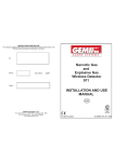
INSTALLATION CERTIFICATE
The undersigned qualified installer attests to have personally fitted the here described vehicle
security system following the manufacturer instructions.
By :
Sold on :
Type of product :
931 PSA
931 PSA
................................................
Vehicle :
..........................................................................................................................
INSTALLATION AND
USE MANUAL
UK
GEMINI Technologies S.p.A.
Via Luigi Galvani 12 - 21020 Bodio Lomnago (VA) - Italia
Tel. +39 0332 943211 - Fax +39 0332 948080
Web site: www.gemini-alarm.com
Reg. n.532-A
UNI EN ISO 9001:2008
Made in Italy
AC 2793 Rev. 00 - 09/10
UK
USER MANUAL
TABLE OF CONTENTS
3.0 - OPERATING DESCRIPTION
1.0 - PRELIMINARY ADVICE............................................................................................. PAGE 02
2.0 - WARRANTY CONDITIONS....................................................................................... PAGE 02
USER MANUAL
3.0 - OPERATING DESCRIPTION..................................................................................... PAGE 03
3.1 - Complete system arming......................................................................................... PAGE 03
3.2 - Arming inhibit time.................................................................................................... PAGE 03
3.3 - System armed.......................................................................................................... PAGE 03
3.4 - Alarm, inhibit time between alarms and alarm cycles.............................................. PAGE 03
3.5 - System disarming..................................................................................................... PAGE 03
3.6 - Alarm memory...........................................................................................................PAGE 03
INSTALLER MANUAL
4.0 - CONNECTORS TABLES............................................................................................ PAGE 04
4.1 - 20-way connector..................................................................................................... PAGE 04
4.2 - 8-way connector....................................................................................................... PAGE 04
5.0 - COMPLETE ELECTRIC DIAGRAM........................................................................... PAGE 05
6.0 - ULTRASONIC VOLUMETRIC PROTECTION............................................................PAGE 05
6.1 - Connections and positioning.................................................................................... PAGE 05
6.2 - Sensor adjustment....................................................................................................PAGE 05
7.0 - WASTE ELECTRICAL AND ELECTRONIC EQUIPMENT (WEEE) DIRECTIVE....... PAGE 0B
8.0 - TECHNICAL SPECIFICATIONS............................................................................... PAGE 0B
1.0 - PRELIMINARY ADVICE
Dear Customer, the present manual illustratesthe 931 PSA CAN enabled alarm system, custom
designed for Peugeot/Citroën vehicles.
Throughout this manual specific operating modes or connections are highlighted by the following
signs:
For the user.
This sign highlights useful information.
!
For the installer.
This sign indicates that the functionning of the system can vary according to
connections and programming of the system or it simply provides useful indications for
the installation.
2.0 - WARRANTY CONDITIONS
This product is guaranteed to be free from manufacturing defects for a period of 24 months from the
installation date shown on this warranty, in compliance with the directive 1999/44/CE.
Please fill-in entirely the guarantee certificate included in this booklet and do NOT REMOVE the
guarantee label from the device.
The warranty will become void if labels are missing or torn, if the installation certificate is not fully
compiled or if the enclosed sale document is missing.
The guarantee is valid exclusively at Authorized Gemini Technologies S.p.A. Centers.
The manufacturer declines any responsibility for eventual malfunctions of the device or any damage
to the vehicle electrical system due to improper installation, use or tampering.
This alarm system is solely intended to be a theft-deterrent device.
PAGE 02
3.1 - COMPLETE SYSTEM ARMING
Press the lock button on the original remote control of the vehicle; the system arming is confirmed by
the LED turned on steady for 30” (pre-arming “neutral time”).
3.2 - ARMING INHIBIT TIME
System inhibit arming time lasts approximately 30 seconds and is indicated by the status LED on; it is
possible to exit the vehicle without triggering any alarm.
3.3 - SYSTEM ARMED
After the inhibit time the system is “armed” and ready to detect any theft attempt.
When the system is fully armed, the LED flashes.
3.4 - ALARM, INHIBIT TIME BETWEEN ALARMS AND ALARM CYCLES
The system theft attempts is indicated by the system with optic signals (turn indicators) and acoustic
signals (vehicle horn).
After the alarm has been triggered, but before another alarm starts, there are 5” of “neutral time”.
The alarm signalling has 10 cycles of 30” each for input and system arming cycles.
3.5 - SYSTEM DISARMING
Press the unlock button on the original remote control of the vehicle; the system disarming is
confirmed by the status LED off (blinking).
If an alarm has occurred, the LED starts flashing when ignition key is turned “ON” to signal the last
alarm type.
See relative paragraph (3.6) for possible causes and signals.
To disarm the system in case of emergency (remote control out of order), simply turn ignition
key “ON” with system armed.
This type of disarming can ONLY be done with the vehicle ORIGINAL KEY.
3.6 - ALARM MEMORY
As previously mentioned, the LED memory allows you to identify the last alarm cause.
After disarming the system, turn the ignition key “ON” and look at the vehicle status LED; the blinks
indicates the last alarm condition.
The optic signals are repeated 3 times; to interrupt, turn ignition key “OFF”.
The alarm trigger signals and relative causes are indicated in the table below.
LED SIGNALS
LED OFF (2 seconds)
ALARM CAUSES
Nr. OF ALARM
CYCLES
Starting attempt (+15/54)
10
Doors opening
10
Bonnet opening
10
Volumetric sensor
10
LED ON (1 second)
USER MANUAL- PAGE 03
INSTALLER MANUAL
5.0 - COMPLETE ELECTRIC DIAGRAM
For the system to work properly, the “original alarm installed” feature (BSI unit)
must first be enabled via the specific diagnostic tester available at any authorized
Peugeot-Citroën dealer (PSA group).
Moreover, this type of system DOES NOT require that you program the vehicle
code, it is already factory-registered by Gemini.
NEVER PRESS THE PROGRAMMING BUTTON LOCATED NEXT TO THE UNIT
BUILT-IN LED
!
Before carrying out all
electrical connections,
disconnect the
negative battery
terminal and reconnect again after
completion.
!
4.0 - CONNECTORS TABLES
4.1 - 20-WAY CONNECTOR
POSITION
WIRE FUNCTION
WIRE COLOUR
-1-
-----
-----
-2-
-----
-----
-3-
-----
-----
-4-
-----
-----
-5-
-----
-----
-6-
-----
-----
-7-
Grund for external sensor connector
BROWN
-8-
LED negative output
BLACK
-9-
LED positive output
RED
- 10 -
-----
-----
- 11 -
CAN BUS signal (CAN-H)
LIGHT BLUE-GREY
- 12 -
CAN BUS signal (CAN-L)
LIGHT BLUE
- 13 -
Positive output with system armed (+A)
PINK
- 14 -
External sensor negative input
GREEN-BLACK
- 15 -
-----
-----
- 16 -
-----
-----
- 17 -
-----
-----
- 18 -
-----
-----
- 19 -
-----
-----
- 20 -
-----
----
4.2 - 8-WAY CONNECTOR
POSITION
WIRE FUNCTION
WIRE COLOUR
-1-
Ground
BLACK
-2-
-----
-----
-3-
Positive
RED
-4-
-----
-----
-5-
-----
-----
-6-
-----
-----
-7-
-----
-----
-8-
-----
-----
PAGE 04 - INSTALLER MANUAL
RED
Red
Black
BLACK
LIGHT BLUE (CAN-L)
Green-Black
Brown
Pink
Connector for external modules
6
3
CAN BUS signal
LIGHT BLUE-GREY (CAN-H) 4
1
6-way connector to plug into
the free connector marked
“EA” on the BSI control unit
6.0 - ULTRASONIC VOLUMETRIC PROTECTION
6.1 - CONNECTIONS AND POSITIONING
Insert the WHITE connector in the the “W” socket on the control unit.
Insert the RED connector in the “R” socket on the control unit.
Install the transducers of the ultrasonic sensors on the top part of the windscreen internal pillars, away
from the aeration inlets and orient them towards the center of the rear window.
6.2 - SENSOR ADJUSTMENT
o check sensors proceed as follows:
! With system disarmed, roll down the front window approx. 20 cm.
! Set the trimmer on the control unit to the middle position.
! Close doors, bonnet and boot and arm the system.
! During the system inhibit arming time, introduce an object in the cabin and move it around; the
status LED will turn off to signal a presence.
! If sensibility level is too low, adjust trimmer again and repeat above procedure.
ULTRASONIC
CELLS
CONNECTIONS
SENSIBILITY
ADJUSTMENT
INSTALLER MANUAL - PAGE 05
7.0 - DIRETTIVA RIFIUTI DI APPARECCHIATURE ELETTRICHE
ED ELETTRONICHE (RAEE)
7.0 - WASTE ELECTRICAL AND ELECTRONIC EQUIPMENT
(WEEE) DIRECTIVE
Nell’Unione Europea, questa etichetta indica che, questo prodotto, non deve essere smaltito
unitamente ai rifiuti domestici ma deve essere depositato presso un impianto adeguato ed in grado di
eseguire le operazioni di recupero, smaltimento e riciclaggio (normative 2002/95/CE, 2002/96/CE e
2003/108/CE).
Per le informazioni sulle procedure di riciclaggio responsabile di questo prodotto nel proprio Paese
visitare il sito: www.eur-lex.europa.eu
NelIn the European Union, this lable indicated that this product should not be disposed of with
household waste. It should be deposited at an appropriate facility to enable recovery and recycling
(directive 2002/95/CE, 2002/96/CE and 2003/108/CE).
For information on how to recycle this product responsibly in your Country, please visit the web-site:
Www.eur-lex.europa.eu
!
!
APPROPRIATE
CONTAINER ONLY
SOLO
CONTENITORI
APPROPRIATI
8.0 - TECHNICAL SPECIFICATIONS
8.0 - CARATTERISTICHE TECNICHE
Tensione nominale
12 Vdc
Assorbimento di corrente @ 12Vdc a sistema inserito e LED lampeggiante
15 mA
Range temperatura di funzionamento
Da -30°C a +70°C
Durata di un ciclo d’allarme
30 sec.
Power supply
12 Vdc
Current absorption @ 12Vdc with system armed and LED flashing
15 mA
Working range temperature
Da -30°C a +70°C
Alarm cycle duration
30 sec.
PAGE 0B