1
Kramer Electronics, Ltd.
USER MANUAL
Model:
VS-3232A
32x32 Audio Matrix Switcher
Contents
Contents
1
2
2.1
3
4
4.1
5
6
6.1
7
7.1
Introduction
Getting Started
Quick Start
Overview
Your Balanced Stereo Audio Matrix Switcher
Using the IR Transmitter
Installing the VS-3232A in a Rack
Connecting a Single VS-3232A 32x32 Audio Matrix Switcher
Connecting the Balanced/Unbalanced Stereo Audio Input/Output
VS-3232A 32x32 Audio Matrix Switcher Configurations
The VS-3232A Configuration Setups
1
1
1
3
3
8
9
10
11
12
12
7.1.1
7.1.2
7.1.3
The Follow-System Configuration Setup
The Master/Slave Configuration Setup
The Follow-System versus the Master/Slave Configuration Setups
12
14
16
7.2
7.3
7.4
7.5
Assembling a Multi-channel Audio Switcher
17
Connecting the VS-3232A as a Companion to the VS-3232V(xl)
18
Connecting the VS-3232A as a Companion to a Multi-channel Video Switcher 19
DIP-switch Settings
20
7.5.1
Setting the Machine #
21
7.6
Connecting a Control Interface
21
7.6.1
7.6.2
Connecting the RS-232 Control Interface
Connecting the RS-485 Control Interface
21
23
7.7
7.8
Setting the Sync
Controlling via the ETHERNET
25
26
7.8.1
7.8.2
7.8.3
Connecting the ETHERNET Port directly to a PC (Crossover Cable)
26
Connecting the ETHERNET Port via a Network Hub (Straight-Through Cable) 27
Control Configuration via the Ethernet Port
27
8
8.1
Operating Your Video Matrix Switcher
Startup Display
8.1.1
Viewing the Display
29
8.2
8.3
Using the Keypad Buttons
Confirming Actions
29
29
8.3.1
8.3.2
Toggling between the At Once and Confirm Modes
Confirming a Switching Action
30
30
8.4
Switching Options
30
8.4.1
8.4.2
8.4.3
8.4.4
8.4.5
Switching one Input to one Output
Switching Several Inputs to Several Outputs
Switching one Input to all Outputs
Clearing an Output
Clearing Several Outputs
31
31
32
32
32
28
28
i
Contents
8.4.6
Clearing all Outputs
32
8.5
Storing and Recalling Setups
33
8.5.1
8.5.2
Storing Setups
Recalling Setups
33
34
8.6
8.7
8.8
8.9
9
9.1
9.2
9.3
9.4
9.5
9.6
9.7
9.8
9.9
10
10.1
Using the DEFAULT SETUP Button (Unity Setting)
Choosing the FOLLOW or the BREAKAWAY Modes
Using the LOCK Button
Setting the Input/Output Volume
The MENU Commands
Selecting the Audio Switching Method
Selecting the SYNC Configuration
Selecting the INTERFACE Configuration
Selecting the Interface REPLY Configuration
Selecting the PROTOCOL Configuration
Selecting the Store DEFAULT Setup Configuration
Selecting the Initialization Sequence Delay Time for a Slave Unit
The Main Firmware Version
Selecting the TOTAL RESET Option
Flash Memory Upgrade
Switcher Flash Memory Upgrade
34
35
37
37
39
41
41
41
42
42
42
43
43
44
45
45
10.1.1 Downloading from the Internet
10.1.2 Connecting the PC to the RS-232 Port
10.1.3 Upgrading Firmware
45
45
46
10.2
50
Ethernet Flash Memory Upgrade
10.2.1 Downloading from the Internet
10.2.2 Connecting the PC to the RS-232 Port
10.2.3 Upgrading Firmware
50
50
51
11
11.1
12
12.1
12.2
12.3
52
53
54
54
59
60
Technical Specifications
Audio Performance Graphs
Communication Protocols
The Kramer 2000 Communication Protocol
Audio Gain/Attenuation Commands
ASCII (Sierra) Protocol for 3232A Series Switcher
12.3.1 ASCII Protocol Available Commands
60
Figures
Figure 1: Front Panel VS-3232A 32x32 Audio Matrix Switcher
Figure 2: VS-3232A Keypad Selector Buttons
Figure 3: Rear Panel VS-3232A 32x32 Audio Matrix Switcher
Figure 4: Connecting the VS-3232A Audio Matrix Switcher
Figure 5: Connecting a Balanced VS-3232A Stereo Audio Input and Output
Figure 6: Connecting an Unbalanced VS-3232A Stereo Audio Input
Figure 7: Connecting an Unbalanced VS-3232A Stereo Audio Output
ii
4
6
7
10
11
11
11
KRAMER: SIMPLE CREATIVE TECHNOLOGY
Contents
Figure 8: Connecting in the Follow-System Configuration Setup
13
15
Figure 9: Connecting in the Master/Slave Configuration Setup
Figure 10: The Follow-System Combined with the Master/Slave Configuration Setup 16
Figure 11: Configuring a 4-channel 32x32 Switcher with Two VS-3232A Switchers
17
18
Figure 12: Connecting the VS-3232A as a Companion to the VS-3232Vxl
19
Figure 13: Connecting the VS-3232A as a Companion to a Multi-channel Switcher
20
Figure 14: DIP-switches
Figure 15: Connecting a PC to two VS-3232A Units
22
23
Figure 16: RS-485 Connector PINOUT
Figure 17: Connecting the RS-485 Connectors between VS-3232A/VS-3232V(xl) Units 24
25
Figure 18: RS-485 Control Interface and SYNC Connections
Figure 19: Local Area Connection Properties Window
27
27
Figure 20: Internet Protocol (TCP/IP) Properties Window
28
Figure 21: Default Startup Status Display Sequence
40
Figure 22: Setting the SYNC Configuration (an example)
Figure 23: Splash Screen
46
46
Figure 24: Atmel – Flip Window
47
Figure 25: Device Selection Window
47
Figure 26: Device Selection window
Figure 27: Loading the Hex
48
48
Figure 28: RS-232 Window
49
Figure 29: Atmel – Flip Window (Connected)
49
Figure 30: Atmel – Flip Window (Operation Completed)
51
Figure 31: The KFR-Programmer Window
Figure 32: Frequency Response (Bandwidth) of the VS-3232A
53
53
Figure 33: THD+N of the VS-3232A
53
Figure 34: Maximum Input/Output Level at 1kHz
54
Figure 35: Linearity of the VS-3232A
Figure 36: Spectrum Plot of the Output Signal for a 1kHz, 4dBu Input
54
iii
Contents
Tables
Table 1: Front Panel VS-3232A 32x32 Audio Matrix Switcher Features
Table 2: VS-3232A Keypad Selector Buttons Functions
Table 3: Rear Panel VS-3232A 32x32 Audio Matrix Switcher Features
Table 4: Follow-System versus the Master/Slave Configuration Setup
Table 5: DIP-switch Settings for VS-3232A and VS-3232V(xl) Switchers
Table 6: DIP-switch Definitions
Table 7: Machine # DIP-switch Settings
Table 8: Audio Output Attenuation Steps
Table 9: Audio Switching Method Configuration Menu
Table 10: SYNC Configuration Menu
Table 11: INTERFACE Configuration Menu
Table 12: Interface REPLY Configuration Menu
Table 13: PROTOCOL Configuration Menu
Table 14: Initialization Sequence Delay Time
Table 15: Total Reset Menu
Table 16: Technical Specifications of the VS-3232A Video Matrix Switcher
Table 17: Hex Table (IN 1-32 to OUT 1-16)
Table 18: Hex Table (IN 1-32 to OUT 17-32)
iv
5
6
8
16
20
20
21
37
41
41
41
42
42
43
44
52
55
57
KRAMER: SIMPLE CREATIVE TECHNOLOGY
Introduction
1
Introduction
Welcome to Kramer Electronics! Since 1981, Kramer Electronics has been
providing a world of unique, creative, and affordable solutions to the vast range
of problems that confront the video, audio, presentation, and broadcasting
professional on a daily basis. In recent years, we have redesigned and upgraded
most of our line, making the best even better! Our 1,000-plus different models
now appear in 11 groups1 that are clearly defined by function.
Thank you for purchasing your Kramer VS-3232A 32x32 Balanced Stereo
Audio Matrix Switcher.
This product is ideal for the following typical applications:
• Professional display systems requiring audio signal routing
• Broadcast, presentation and production facilities
• Rental/staging applications
• Monitoring in large duplication systems
The package includes the following items:
• VS-3232A 32x32 Audio Matrix Switcher
• Windows®-based Kramer control software
• Power cord and Null-modem adapter
• This user manual2
2
Getting Started
We recommend that you:
• Unpack the equipment carefully and save the original box and packaging
materials for possible future shipment
• Review the contents of this user manual
• Use Kramer high-performance high-resolution cables3
2.1
Quick Start
This quick start chart summarizes the basic setup and operation steps.
1 GROUP 1: Distribution Amplifiers; GROUP 2: Switchers and Routers; GROUP 3: Control Systems; GROUP 4:
Format/Standards Converters; GROUP 5: Range Extenders and Repeaters; GROUP 6: Specialty AV Products; GROUP 7:
Scan Converters and Scalers; GROUP 8: Cables and Connectors; GROUP 9: Room Connectivity; GROUP 10: Accessories
and Rack Adapters; GROUP 11: Sierra Products
2 Download up-to-date Kramer user manuals from our Web site at http://www.kramerelectronics.com
3 The complete list of Kramer cables is on our Web site at http://www.kramerelectronics.com
1
Getting Started
2
KRAMER: SIMPLE CREATIVE TECHNOLOGY
Overview
3
Overview
The VS-3232A is a high-performance 32x32 matrix switcher (router) for
analog balanced stereo audio signals. The unit can route any or all inputs to
any or all outputs simultaneously.
The VS-3232A features:
• Clean switching (noise free)
• Level control for each input and output
• An S/N ratio of over 100dB at +20dBu/1kHz and a linearity better than
0.1dB from -25dBu to +20dBu
• THD and noise below 0.03%
• A flat frequency response from 20Hz to 20kHz (±0.1dB)
• The ability to operate as a standalone audio router or as a companion
router to the VP-3232V(xl)
• The ability when connected to the VP-3232V(xl), to operate in audio-followvideo or breakaway mode
• Flexible control options: front panel, remote control via RS-232
(K-Router™ Windows®-based software is included), RS-485, Ethernet
and IR remote (included)
• A TAKE button for executing multiple switches all at once
• 60 memory locations to store the machine's full status such as presets to be
recalled and executed when needed. One "Default" setup can be executed
immediately by pressing the default button
• Front panel lockout
• Two optional communication protocols, the Kramer 2000 and Sierra
ASCII protocols (partial)
• A worldwide power supply, 100-240V AC on a standard 19” rack mount
size, with 2U Rack "ears" included
To achieve the best performance:
• Use only good quality connection cables to avoid interference,
deterioration in signal quality due to poor matching, and elevated noise
levels (often associated with low quality cables)
• Avoid interference from neighboring electrical appliances that may
adversely influence signal quality and position your VS-3232A away from
moisture, excessive sunlight and dust
4
Your Balanced Stereo Audio Matrix Switcher
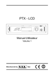
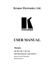
Figure 1 and Table 1 define the front panel of the VS-3232A.
3
Your Balanced Stereo Audio Matrix Switcher
1
2
3
4
5
6
7
8
9
0
TAKE
MENU
LOCK
Figure 1: Front Panel VS-3232A 32x32 Audio Matrix Switcher
4
KRAMER: SIMPLE CREATIVE TECHNOLOGY
Your Balanced Stereo Audio Matrix Switcher
Table 1: Front Panel VS-3232A 32x32 Audio Matrix Switcher Features
#
1
Feature
IR Receiver
2
3
4
5
6
7
POWER Switch
Keypad
FOLLOW Button
BREAKAWAY Button
DEFAULT SETUP Button
INPUTS/OUTPUTS LCD
Display
8
9
LOCK Button
MENU Button
10
TAKE Button
Function
The red LED is illuminated when receiving signals from the Kramer infrared
remote control transmitter
Illuminated switch for turning the unit ON or OFF
See Figure 2 and Table 2
Press to enter the Follow mode in the multi-switcher configuration
Press to enter the Standalone mode in the multi-switcher configuration
Press to recall the default setup (UNITY setting), see section 9.6
Displays the outputs (in the upper row) switched to the selected inputs (in the
lower row).
Displays user interface messages and configuration menu items
1
Toggle to lock/unlock the front panel buttons
Press once to enable the ALL, OFF STO and RCL buttons
Press twice to enter the audio input/output volume control menu
Press three times to enter the configuration menu
When in the configuration menu, press to browse through the menu items
Used to confirm and complete setup and switching
1 Press and hold the LOCK button for about two seconds to toggle
5
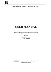
Your Balanced Stereo Audio Matrix Switcher
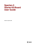
The keypad selector buttons (illustrated in Figure 2 and Table 2) are used to
select the outputs and the inputs when routing1. Use the keypad button to
shift the display content to the left, and the keypad button to shift the
display content to the right (as the LCD display is only large enough to show
13 cross-points out of a total of 32). Most keypad buttons have more than one
function, as defined in Table 2.
Table 2: VS-3232A Keypad Selector Buttons Functions
Keypad #
1
1
2
3
4
5
6
7
8
9
0
Figure 2: VS-3232A Keypad
Selector Buttons
Function
ALL2 – Press ALL followed by an input number to
connect that input to all the outputs
LEFT – Press to select the left channel of a selected
input or output3
2
L+R (Left and Right) – Press to select both left and
right channels of a selected input or output
3
OFF – Press OFF followed by an output number
to disconnect that output
RIGHT – Press to select the right channel of a
selected input or output
4
STO2 – Press to store the current setting in the nonvolatile memory
6
RCL2 – Press to recall a setup from the
non-volatile memory
7
LEVEL UP – Press to increase the audio output
level of the selected input or output4
9
LEVEL DOWN – Press to decrease the audio level
of the selected input or output4
(Backward)
ESC – Press to exit the current operation
(Forward)
ENT – Press to complete the input-output setup
when using a one-digit number instead of two digits5
Press to enter the options in a setup menu
2
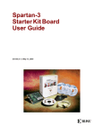
Figure 3 and Table 3 define the rear panel of the VS-3232A.
1 See Section 8.4
2 This button is enabled and illuminated after pressing the MENU button
3 For audio level adjustment
4 You can adjust the left, right or both channels of an input or an output
5 For example, to enter input 5, you can either press 0, 5 or 5, ENT
6
KRAMER: SIMPLE CREATIVE TECHNOLOGY
Your Balanced Stereo Audio Matrix Switcher
Figure 3: Rear Panel VS-3232A 32x32 Audio Matrix Switcher
7
Your Balanced Stereo Audio Matrix Switcher
Table 3: Rear Panel VS-3232A 32x32 Audio Matrix Switcher Features
#
1
2
3
4
5
6
7
8
9
10
11
12
Feature
INPUT Terminal Block
Connectors
OUTPUT Terminal Block
Connectors
FLASH MAIN Button
Function
Connect to the balanced stereo audio sources (from 1 to 32)
Connect to the balanced stereo audio acceptors (from 1 to 32)
Push in1 to upgrade the switcher microcontroller to the latest Kramer
firmware (see Section 10.1), or release (the factory default) for normal
operation
RS-232 IN 9-pin D-sub F Port
Connects to the PC or the Remote Controller2
RS-232 OUT 9-pin D-sub M Port Connects to the RS-232 IN 9-pin D-sub F port of the next unit in the
daisy-chain connection
RS-485 Detachable Terminal
The A and B PINs are for RS-485, and the SYNC and the G PINs are
Block Port
for vertical sync and ground connection, respectively
SETUP DIP-switches
For setup of the unit (see Section 7.5)
1
FLASH Button
Push in to upgrade the ETH FLASH firmware version (see section
10.2), or release (the factory default) for normal operation
ETHERNET Connector
Connects to the PC or other Serial Controller through computer
networking LAN
3
FACTORY RESET Button
Press to reset to factory default definitions :
IP Address:
192.168.1.39
Mask:
255.255.255.0
Gateway:
192.168.1.1
REMOTE IR 3.5mm Mini Jack
Connects to an external IR receiver unit4 for controlling the machine via
an IR remote controller (instead of using the front panel IR receiver)
Power Connector with Fuse
AC connector enabling power supply to the unit
4.1 Using the IR Transmitter
You can use the RC-IR2 IR transmitter to control the machine via the built-in
IR receiver on the front panel or, instead, via an optional external IR receiver5.
The external IR receiver can be located up to 15 meters away from the
machine. This distance can be extended to up to 60 meters when used with
three extension cables6.
Connect the external IR receiver to the REMOTE IR 3.5mm connector.
1 Using a small screwdriver, if required
2 If the unit is not the first unit in the line, connects to the RS-232 OUT 9-pin D-sub F port of the previous unit in the line
3 Turn the machine OFF using the power switch and then turn it ON while pressing the ETH Factory Reset button. The unit
will power up and load its memory with the factory default definitions
4 Can be used instead of the front panel (built-in) IR receiver to remotely control the machine
5 Model: C-A35M/IRR-50
6 Model: C-A35M/A35F-50
8
KRAMER: SIMPLE CREATIVE TECHNOLOGY
Installing the VS-3232A in a Rack
5
Installing the VS-3232A in a Rack
This section describes what to do before installing on a rack and how to rack
mount.
9
Connecting a Single VS-3232A 32x32 Audio Matrix Switcher
6
Connecting a Single VS-3232A 32x32 Audio Matrix Switcher
To connect the VS-3232A as illustrated in the example in Figure 4, do the
following1:
1. Connect up to 32 balanced audio sources2.
2. Connect up to 32 balanced audio acceptors2.
3. Set the DIP-switches (see Section 7.5).
4. If required, connect a PC or controller to the RS-232 port (see Section
7.6.1) or the RS-485 port (see Section 7.6.2) or the ETHERNET port (see
Section 7.8).
5. Connect the power cord3.
If necessary, review and set the system variables, using the MENU function,
and the default setup (UNITY setting) as Section 9 describes.
Figure 4: Connecting the VS-3232A Audio Matrix Switcher
1 Switch OFF the power on each device before connecting it to your VS-3232A
2 You do not have to connect all the inputs and the outputs. In this example only two inputs (two DAT players) and two
outputs (a power amplifier with speakers and a DAT recorder) are connected
3 We recommend that you use only the power cord that is supplied with this machine
10
KRAMER: SIMPLE CREATIVE TECHNOLOGY
Connecting a Single VS-3232A 32x32 Audio Matrix Switcher
6.1
Connecting the Balanced/Unbalanced Stereo Audio Input/Output
This section illustrates how to wire:
• A balanced stereo audio input and output, see Figure 5
• An unbalanced stereo audio input, see Figure 6
• An unbalanced Stereo Audio Output, see Figure 7
Figure 5: Connecting a Balanced VS-3232A Stereo Audio Input and Output
Figure 6: Connecting an Unbalanced VS-3232A Stereo Audio Input
Figure 7: Connecting an Unbalanced VS-3232A Stereo Audio Output
11
VS-3232A 32x32 Audio Matrix Switcher Configurations
7
VS-3232A 32x32 Audio Matrix Switcher Configurations
The VS-3232A belongs to a series of 32x32 matrix switchers, including the
VS-3232V and the VS-3232Vxl, and as such, can interconnect with them. The
following sections describe:
• The VS-3232A configuration setups (see Section 7.1)
• Various matrix configurations (see Sections 7.2, 7.3, and 7.4)
• The DIP-switch setup (see Section 7.5)
• How to connect a control interface (see Section 7.6)
• How to set the SYNC (see Section 7.7)
• How to control via the Ethernet (see Section 7.8)
7.1 The VS-3232A Configuration Setups
The VS-3232A includes two configuration setups: the Follow-System setup
(see Section 7.1.1) and the Master/Slave setup (see Section 7.1.2).
7.1.1 The Follow-System Configuration Setup
The Follow-System configuration allows communication between the connected
units via a common control line.
In the Follow-System configuration setup:
• Any type of signal can follow one or more signals within the setup at your
choice
• Any unit can be turned ON or OFF at any time
• The LCD display on each unit shows the switching operations
independently
Each unit within this configuration can be switched in the FOLLOW or
BREAKAWAY state (via the FOLLOW or BREAKAWAY front panel
buttons) at any time, depending on the current application requirements.
When the:
• FOLLOW button is pressed, signals are switched simultaneously
• BREAKAWAY button is pressed, each machine in the configuration setup
is switched independently
By default, the matrix switchers are set to the BREAKAWAY state (meaning
that each machine switches independently from the other machines in the
configuration setup).
Pressing the FOLLOW button on one machine and then on other machines,
sets them searching for other machines, and they can follow each other
without reference to the order in which they are connected. In this state,
12
KRAMER: SIMPLE CREATIVE TECHNOLOGY
VS-3232A 32x32 Audio Matrix Switcher Configurations
switching an input to an output on one machine, switches the same input to
the same output on the other machines in the FOLLOW state.
DIP 5 defines whether the VS-3232A unit can communicate with other
switchers via a common control line. Set DIP 5 to:
• ON, to enable the Follow-System configuration setup
• OFF, to disable the Follow-System configuration setup
Set the machine number on each machine to a different value.
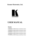
The example illustrated in Figure 8 shows three 32x32 matrix switchers: one
composite video (CV) switcher (the VS-3232Vxl) and two VS-3232A audio
switchers (A1 for the “English” language, and A2 for the “French” language).
DIP 5 is set to ON and DIP 6 is set to OFF on all the switchers. Each unit
within the system is set to a different machine number (see Section 7.5.1).
VS-3232Vxl
CV
DIP 6 OFF (Master)
RS-485
DIP 5 ON
VS-3232A
A1 - English
RS-485
VS-3232A
A2 - French
Figure 8: Connecting in the Follow-System Configuration Setup
The Follow-System configuration Setup lets you operate the system in the
following way:
• Initially, all three units are set to the Breakaway state. This means that
each unit operates independently, as a standalone unit
• Pressing the FOLLOW button on the two audio switchers, sets them
searching for other machines they can follow within the communication
line
At this state, the video switcher still operates as a standalone unit, but the
audio switchers follow each other: for example, switching input 1 to
output 16 on the English language audio switcher, switches input 1 to
input 16 on the French language audio switcher
13
VS-3232A 32x32 Audio Matrix Switcher Configurations
• Pressing the FOLLOW button on the CV switcher too, sets it searching for
the other machines in the FOLLOW state
At this state, all three switchers follow each other: for example, switching
input 1 to output 16 on the English language audio switcher, switches
input 1 to output 16 on the French language audio switcher and on the CV
switcher. Alternatively, you switch the CV switcher and have both audio
switchers follow
• To return to independent switching, simply press the BREAKAWAY
button on the switcher
7.1.2 The Master/Slave Configuration Setup
The Master/Slave configuration setup is only used for the multi-channel switchers
configuration: one unit is set to be the Master and the other units are set to be the
Slaves. The Slave units always follow the Master, they cannot be set to work as a
standalone, unless you turn them off and change the DIP-switch settings.
In the Master/Slave configuration setup, the Slave unit initializing-sequence
always follows the Master unit initialization-sequence, and the entire setup
sequence is automatic (the Master–slave system automatically sets the master
and the slave setup follows).
If several slave units are connected in a Master/Slave configuration, the
initialization delay time for each of the Slave units (except for the first slave in
the sequence) should be programmed via the menu, as described in Section
9.7.
To change the initializing sequence delay time for a Slave unit via the menu,
set DIP 6 to OFF and turn the unit ON separately in the Master mode.
On the Slave VS-3232A unit, the LCD display1, shows the following message
upon initialization2:
The unit set in SLAVE mode
Front panel completely LOCKED
However, during normal operation, the display on the Slave VS-3232A unit
dynamically shows3 all the changes that were made in the Master VS-3232A unit.
The front panel control is managed via the Master unit, on which the front
panel buttons are unlocked and the LCD display illuminates.
1 At the time of powering the machines ON
2 Or when pressing any of the front panel buttons (by mistake)
3 Albeit with an LCD Display that does not illuminate
14
KRAMER: SIMPLE CREATIVE TECHNOLOGY
VS-3232A 32x32 Audio Matrix Switcher Configurations
The BREAKAWAY and FOLLOW front panel buttons have no effect in the
Master/Slave configuration setup since the connected machines act as one unit
in one box.
DIP 6 determines the operation mode of each unit within the Master/Slave
configuration setup. DIP 6 is set to:
• ON, for the Slave units in the configuration setup
• OFF, for the Master unit in the configuration setup
Set the machine number on all the machines to the same value.
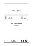
The example illustrated in Figure 9 shows three 32x32 matrix switchers: one
composite video switcher and two audio switchers. DIP 5 is set to OFF on all
three switchers and DIP 6 is set to OFF on the CV VS-3232Vxl switcher (the
Master) and to ON on the two VS-3232A audio switchers1 (the Slaves). All
the units have the same machine number (see Section 7.5.1).
VS-3232Vxl
CV
DIP 6 OFF (Master)
RS-485
DIP 5 OFF
VS-3232A
A1 - English
RS-485
VS-3232A
A2 - French
Figure 9: Connecting in the Master/Slave Configuration Setup
In this example, the Slaves always follow the Master, and both machines act
as a single unit.
Switching input 1 to output 16 on the CV switcher, switches input 1 to output
16 on the English language audio switcher and on the French language audio
switcher. In this state you cannot perform this switching operation on any of
the audio switchers and have the CV switcher follow, or set any of the
machines in this configuration to operate independently (as a standalone unit),
unless you turn OFF the machines and change the DIP-switch settings.
1 A1 for the “English” language, and A2 for the “French” language
15
VS-3232A 32x32 Audio Matrix Switcher Configurations
7.1.3 The Follow-System versus the Master/Slave Configuration Setups
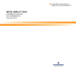
The example illustrated in Figure 10 shows three 32x32 matrix switchers: one
composite video switcher and two audio switchers. DIP 5 is set to ON on all
the units. DIP 6 is set to OFF on the CV VS-3232Vxl switcher and on the A1
English language VS-3232A audio switcher. DIP 6 is set to ON on the A2
French language VS-3232A audio switcher.
VS-3232Vxl
CV
DIP 6 OFF (Master)
RS-485
DIP 5 ON
VS-3232A
A1 - English
RS-485
VS-3232A
A2 - French
Figure 10: The Follow-System Combined with the Master/Slave Configuration Setup
In this example, the audio switchers are in the Master/Slave configuration
setup (the French language switcher always follows the English language
switcher). The CV switcher and the combined audio switcher unit are in the
Follow-System configuration setup.
Table 4 summarizes the differences between the Follow-System configuration
setup and the Master/Slave configuration setup:
Table 4: Follow-System versus the Master/Slave Configuration Setup
Follow-System Configuration Setup
Several units are connected in a common control line.
The unit can be switched in the FOLLOW or
BREAKAWAY state at any time (using the FOLLOW
and BREAKAWAY front panel buttons), depending on
the current application requirements.
Master/Slave Configuration Setup
One unit is set as the Master, the others as slaves.
The Slaves always follow the Master. The machines
cannot operate as standalone units without turning
off and changing the DIP-switch settings.
The FOLLOW/BREAKAWAY state is not applicable
because the connected machines act as one unit.
Any unit can be turned on or off at any time.
The Slave unit can be turned ON only after full
initialization of the Master unit.
Each machine has a different machine number value.
All the machines have the same machine number.
16
KRAMER: SIMPLE CREATIVE TECHNOLOGY
VS-3232A 32x32 Audio Matrix Switcher Configurations
7.2
Assembling a Multi-channel Audio Switcher
The example in Figure 11 illustrates a 4-channel 32x32 configuration
consisting of two VS-3232A units. Broadcasting applications often use four
channels, to broadcast stereo audio sound in two languages (say, English and
French) or to produce surround sound.
DIP 6 is set to OFF on the master unit and set to ON on the Slave unit.
The front panel of the Slave unit is always locked and the LCD display does
not illuminate. The Slave unit follows the Master. The Master unit operates in
the regular way, that is, its front panel is not locked and the LCD display
illuminates, leading the Slaves in the background.
When turning the system ON, the Slave unit initialization sequence
automatically follows the Master unit initialization sequence.
IN OUT
A B A B
1
2
3
4
5
6
7
8
Master
ON
IN OUT
C D C D
A B A B
IN OUT
1
ON
2
3
4
5
6
7
8
Slave
C D C D
IN OUT
… 32
1
INPUTS
(A, B, C, D)
1 … 32
OUTPUTS
(A, B, C, D)
Figure 11: Configuring a 4-channel 32x32 Switcher with Two VS-3232A Switchers
17
VS-3232A 32x32 Audio Matrix Switcher Configurations
7.3 Connecting the VS-3232A as a Companion to the VS-3232V(xl)
You can connect the VS-3232A as an analog audio companion to the VS-3232Vxl
32x32 Video Matrix Switcher, as illustrated in the example in Figure 12.
To connect the VS-3232A as a companion to the VS-3232Vxl, do the
following:
1. Connect the required inputs and outputs to the VS-3232A and the
VS-3232Vxl.
2. Connect the two switchers via the RS-232 or RS-485 control interface (see
Section 7.6).
3. Set the DIP-switches according to the required configuration setup (see
Section 7.5).
4. Connect the power cord1.
5. If necessary, review and set the system variables, using the MENU function,
and the default setup (UNITY setting) as Section 9 describes.
VS-3232Vxl Video Switcher (Set DIP 6 to OFF)
VS-3232A Audio Switcher - Slave (set DIP 6 to OFF)
Video
Video
Audio
Audio
DVD Player
Power Amplifier with Speakers
Display
Figure 12: Connecting the VS-3232A as a Companion to the VS-3232Vxl
1 We recommend that you use only the power cord that is supplied with this machine
18
KRAMER: SIMPLE CREATIVE TECHNOLOGY
VS-3232A 32x32 Audio Matrix Switcher Configurations
7.4 Connecting the VS-3232A as a Companion to a Multi-channel
Video Switcher
You can connect the VS-3232A to a multi-channel system such as a switcher
for YUV (RGB) by combining three VS-3232Vxl units1.
Y/G Channel Switcher - Master (Set DIP 6 to OFF)
U/B Channel Switcher - Slave (Set DIP 6 to ON)
V/R Channel Switcher - Slave (Set DIP 6 to ON)
VS-3232A Audio Switcher - Slave (set DIP 6 to OFF)
Audio
Audio
V/R
U/B
Y/G
V/R
U/B
Y/G
Component Video Player
Power Amplifier with Speakers
YUV/RGB Display
Figure 13: Connecting the VS-3232A as a Companion to a Multi-channel Switcher
1 You can also assemble an s-Video system (using two VS-3232Vxl units) or an RGBS system (using four VS-3232Vxl
units)
19
VS-3232A 32x32 Audio Matrix Switcher Configurations
Set the DIP-switches as follows:
Table 5: DIP-switch Settings for VS-3232A and VS-3232V(xl) Switchers
Machine Name
VS-3232V(xl)
VS-3232A
Follow-System
Master/Slave
1
Machine #
2
3
4
5
6
Y (G)
ON
OFF
OFF
OFF
ON
OFF
U (B)
ON
OFF
OFF
OFF
ON
ON
V (R)
ON
OFF
OFF
OFF
ON
ON
Audio
OFF
ON
OFF
OFF
ON
OFF
Connect the communication line between the switchers via the RS-232 or
RS-485 control interface as section 7.6 describes.
7.5 DIP-switch Settings
By default all the DIP-switches are set to OFF. Configure the VS-3232A by
setting the eight DIP-switches as Figure 14 and Table 6 define:
FOLLOW-SYSTEM
CONFIGURATION
SETUP
}
MACHINE #
MASTER/SLAVE
CONFIGURATION
SETUP
RS-232 NULL-MODEM
RS-485 TERMINATION
ON
1 2 3 4 5 6 7 8
Figure 14: DIP-switches
Table 6: DIP-switch Definitions
DIP-switch #
Function:
1-4
Set the machine # (see Table 7 in Section 7.5.1)
5
Enables (ON) or disables (OFF) the Follow-System configuration setup in a
multi-switcher configuration
6
Enables (ON) or disables (OFF) the Master/Slave configuration setup in a
multi-channel configuration
7
Disables the use of a null modem adapter1 with RS-232 as follows:
Set OFF for RS-232 input connection via a null modem adapter
Set ON for RS-232 straight connection without a null modem adapter
8
Set ON for RS-485 termination for the first and the last machine (RS-485 line
terminates with 110Ω); for others set OFF (RS-485 line is open)
1 See section 7.6.1
20
KRAMER: SIMPLE CREATIVE TECHNOLOGY
VS-3232A 32x32 Audio Matrix Switcher Configurations
7.5.1 Setting the Machine #
To control a unit remotely via RS-232, RS-485, IR or the Ethernet, each unit
has to be identified via its unique Machine #. Set the Machine #1 on a
VS-3232A unit according to Table 7.
Table 7: Machine # DIP-switch Settings
Mach. #
1
2
3
4
5
6
7
8
DIP 1
ON
OFF
ON
OFF
ON
OFF
ON
OFF
DIP 2
OFF
ON
ON
OFF
OFF
ON
ON
OFF
DIP 3
OFF
OFF
OFF
ON
ON
ON
ON
OFF
DIP 4
OFF
OFF
OFF
OFF
OFF
OFF
OFF
ON
Mach. #
9
10
11
12
13
14
15
DIP 1
ON
OFF
ON
OFF
ON
OFF
ON
DIP 2
OFF
ON
ON
OFF
OFF
ON
ON
DIP 3
OFF
OFF
OFF
ON
ON
ON
ON
DIP 4
ON
ON
ON
ON
ON
ON
ON
7.6 Connecting a Control Interface
You can connect a control interface (RS-232 or RS-485). It is recommended
that the control interfaces are identical on each switcher in the series of 32x32
matrix switchers; either RS-232 or RS-485 (one control interface suffices).
For example, in an interconnected varied-format 32x32 switcher application,
if the switcher that connects to the PC connects via the RS-232 control
interface, each switcher would interconnect via the RS-232 control interface
and not via the RS-485 control interface.
You may transfer from one interface to another via the Kramer VP-43xl
Interface Converter2. You can choose the RS-232 control interface, if the
range is less than 25 meters for each point-to-point connection.
For greater ranges, you can choose the RS-485 control interface, and operate
the switcher from an extended distance of up to 1000 meters.
7.6.1 Connecting the RS-232 Control Interface
You can connect several switchers (from the series of 32x32 or 16x16 matrix
switchers) and the control unit in an RS-232 daisy chain arrangement, with or
without using a Null-modem adapter, as Figure 15 illustrates.
The RS-232 daisy chain switcher arrangement is transparent. This lets you arrange
the switchers (from the series of 32x32 or 16x16 matrix switchers) according to
your requirements, and not according to a fixed sequence dependent on the
Machine #.
1 When using a single unit, set the unit to MACHINE # 1
2 For more information on the VP-43xl, go to our Web site at http://www.kramerelectronics.com
21
VS-3232A 32x32 Audio Matrix Switcher Configurations
With a Null-modem adapter
Set DIP 7 OFF
ON
1 2 3 4 5 6 7 8
Without a Null-modem adapter
Set DIP 7 ON
ON
1 2 3 4 5 6 7 8
Figure 15: Connecting a PC to two VS-3232A Units
You can connect any of the following:
• The 9-pin D-sub COM port of the PC to a VS-3232A unit1 (see Section
7.6.1.1)
• Two VS-3232A units1 or a VS-3232Vxl video matrix switcher2 connected
to a VS-3232A audio matrix switcher, (see Section 7.6.1.2)
Note, turning OFF the power on a unit that is connected as part of an RS-232
daisy-chain will destroy the daisy-chain connection
7.6.1.1
Connecting a PC to a VS-3232A Unit via RS-232
To connect a PC to a VS-3232A unit, using the Null-modem adapter provided
with the machine (the default):
1. Connect the RS-232 IN 9-pin D-sub rear panel port on the Master
VS-3232A unit to the Null-modem adapter and connect the Null-modem
adapter with a cable3 to the RS-232 9-pin D-sub port on your PC.
2. Set DIP 7 OFF4 (enabling Null-modem adapter use) on the VS-3232A unit.
1 With or without the Null-modem adapter
2 Or a multi-channel switch comprising of several VS-3232V(xl) units
3 The cable should consist of at least three straight-through wires for PINs 2, 3 and 5
4 See Section 7.5
22
KRAMER: SIMPLE CREATIVE TECHNOLOGY
VS-3232A 32x32 Audio Matrix Switcher Configurations
To connect a PC to the VS-3232A unit, without using a Null-modem adapter:
1. Connect the RS-232 9-pin D-sub port on your PC to the RS-232 IN 9-pin
D-sub rear panel port on the Master VS-3232A with a 9-wire cable1 to the
RS-232 9-pin D-sub port on your PC.
2. Set DIP 7 ON2 (disabling Null-modem adapter use) on the VS-3232A unit.
7.6.1.2
Connecting two VS-3232A Units via RS-232
To connect two VS-3232A units, using a Null-modem adapter provided with
the machine (the default):
1. Connect a cable between the RS-232 OUT 9-pin D-sub port on the first
VS-3232A unit and the Null-modem adapter that attaches to the RS-232 IN
9-pin D-sub port on the second VS-3232A unit.
2. On the second VS-3232A unit, set DIP 7 OFF4 (enabling Null-modem
adapter use).
To connect two VS-3232A units, without using a Null-modem adapter:
1. Connect a cable between the RS-232 OUT 9-pin D-sub port on the first
VS-3232A unit and the RS-232 IN 9-pin D-sub port on the second
VS-3232A unit.
2. On the second VS-3232A unit, set DIP 7 ON (disabling Null-modem
adapter use).
7.6.2 Connecting the RS-485 Control Interface
Figure 16 defines the RS-485 connector PINOUT for external RS-485 control.
The RS-485 connector is also used (if required) for vertical sync. The A and B
PINs are for RS-485, and the SYNC and the G PINs are for vertical sync and
ground connection, respectively
RS-485
SYNC G B A
Figure 16: RS-485 Connector PINOUT
1 The cable should consist of at least three straight-through wires – PINs 2, 3 and 5 – and PINs 2 and 3 should be crossed
2 See Section 7.5
23
VS-3232A 32x32 Audio Matrix Switcher Configurations
To connect an RS-485 connector on one VS-3232A unit to an RS-485
connector on one or more video switchers (from the series of 32x32 or 16x16
matrix switchers), as Figure 17 illustrates:
1. Connect the “A” PIN on the first VS-3232A unit to the “A” PIN on the
VS-3232Vxl unit and to all the other video units.
2. Connect the “B” PIN on the first VS-3232A unit to the “B” PIN on the
VS-3232Vxl unit and to all the other video units.
3. If shielded twisted pair cable is used, the shield may be connected to the “G”
(Ground) PIN
A
B
G
Sync
If necessary (for a video-audio combination only), connect the SYNC pins
together. For details about how to configure the vertical sync (if required),
refer to Section 7.7 and Section 9.2.
Vertical Sync
Figure 17: Connecting the RS-485 Connectors between VS-3232A/VS-3232V(xl) Units
Figure 18 illustrates the RS-485 line that connects:
• Between the VS-3232Vxl and VS-3232A unit
• To the PC via a Kramer TOOLS VP-43xl Interface Converter (connect the
9-pin D-sub COM port of the PC to the RS-232 IN 9-pin D-sub F port on
the VP-43xl and then connect the RS-485 port on the VP-43xl to the
RS-485 ports on the switcher units)
24
KRAMER: SIMPLE CREATIVE TECHNOLOGY
VS-3232A 32x32 Audio Matrix Switcher Configurations
EXT SYNC
VS-3232Vxl
MACHINE # 1
DIP 8 OFF
VS-3232A
32x32 Video Audio
Switcher
MACHINE # 2
DIP 8 ON
Figure 18: RS-485 Control Interface and SYNC Connections
7.7 Setting the Sync
You can set the VS-3232A to switch simultaneously with video (a sync
derived from another 32x32 or 16x16 series switcher) via the RS-485 sync
terminal block connector1 or set the machine to the immediate switching
mode, in which switching is executed immediately after receiving the
command.
Configure the sync via the SYNC Configuration Menu command setting2.
When setting up a 32x32 video and audio switcher, for example, it may be
necessary to link a common sync to all the machines to facilitate simultaneous
vertical interval switching.
1 When using multiple machines in one system
2 Refer to Section 9.2
25
VS-3232A 32x32 Audio Matrix Switcher Configurations
Usually the easiest method is to choose the sync source from the first video
machine and then connect all the terminal block connectors, as Figure 18
illustrates. In this case, set the first machine to select the sync source from the
external sync connector or from the INPUT # 1 connector1. This sync is now
available to the other machines via the RS-485 terminal block connector, as
the examples in Figure 16, Figure 17 and Figure 18 illustrate. Select the EXTSYS SYNC2 on the other machines that receive that sync.
7.8 Controlling via the ETHERNET
You can connect the VS-3232A via the Ethernet, using a crossover cable (see
Section 7.8.1) for direct connection to the PC or a straight through cable (see
Section 7.8.2) for connection via a network hub or network router3.
7.8.1
Connecting the ETHERNET Port directly to a PC (Crossover Cable)
You can connect the Ethernet port of the VS-3232A to the Ethernet port on
your PC, via a crossover cable with RJ-45 connectors.
This type of connection is recommended for identification of the factory default
IP Address of the VS-3232A during the initial configuration
After connecting the Ethernet port, configure your PC as follows:
1. Right-click the My Network Places icon on your desktop.
2. Select Properties.
3. Right-click Local Area Connection Properties.
4. Select Properties.
The Local Area Connection Properties window appears.
5. Select the Internet Protocol (TCP/IP) and click the Properties Button (see
Figure 19).
1 If the first machine is a VS-3232Vxl Video Matrix Switcher
2 You can also select the immediate switching mode (see Section 9.1), in which the switching operation is executed
immediately after receiving the command. This mode is not a glitch free transition
3 After connecting the Ethernet port, you have to install and configure your Ethernet Port. For detailed instructions, see the
“Ethernet Configuration (FC-11) guide.pdf” file in the technical support section on our Web site:
http://www.kramerelectronics.com
26
KRAMER: SIMPLE CREATIVE TECHNOLOGY
VS-3232A 32x32 Audio Matrix Switcher Configurations
Figure 19: Local Area Connection Properties Window
6. Select Use the following IP Address, and fill in the details as shown in
Figure 20.
7. Click OK.
Figure 20: Internet Protocol (TCP/IP) Properties Window
7.8.2 Connecting the ETHERNET Port via a Network Hub (Straight-Through
Cable)
You can connect the Ethernet port of the VS-3232A to the Ethernet port on a
network hub or network router, via a straight-through cable with RJ-45
connectors.
7.8.3 Control Configuration via the Ethernet Port
To control several units via the Ethernet, connect the Master unit
(Machine # 1) via the Ethernet port to the LAN port of your PC. Use your PC
initially to configure the settings (see Section 7.8).
27
Operating Your Video Matrix Switcher
8
Operating Your Video Matrix Switcher
This section describes:
• The startup display (see Section 8.1)
• How to use the selector buttons (see Section 8.2)
• How to confirm actions (see Section 8.3)
• The switching options (see Section 8.4)
• How to store and recall setups (see Section 8.5)
• The DEFAULT SETUP button (see Section 8.6)
• How to Choose the FOLLOW or the BREAKAWAY modes (see
Section 8.7)
• How to Lock and unlock the front panel (see Section 8.8)
• How to set the Input/Output volume (see Section 8.9)
8.1 Startup Display
After switching on the power, the LCD display1 shows the following screens
in sequence:
KRAMER ELECTRONICS, Ltd
VS-3232A 32 x 32 Stereo Audio matrix
Restore last setup...
01
01
02
02
03
03
04
04
05
05
06
06
07
07
08
08
09
09
10
10
11
11
12
12
13
13
Figure 21: Default Startup Status Display Sequence
The front panel of the VS-3232A includes a numerical keyboard within the
Keypad area2. This keypad includes the numbers from 0 to 9 and lets you
enter both the output and input numbers.
1 The text in the LCD Display may vary (according to machine settings)
2 See Table 1
28
KRAMER: SIMPLE CREATIVE TECHNOLOGY
Operating Your Video Matrix Switcher
8.1.1 Viewing the Display
Figure 21 shows the output-input cross-points on the LCD display. The LCD
display can only show 13 of the 32 input/output combinations.
To view the full contents of the display, shift the contents of the display to the
right or to the left, via the or the buttons on the front panel, respectively.
This function is enabled when:
• The switcher is in between operations (waiting for its next operation while
all previous operations are completed or cancelled )
• Viewing or recalling a setup using the or buttons prior to it execution
When entering an OUT IN combination, the contents of the LCD display
automatically shift to indicate the current status of the selected output.
8.2 Using the Keypad Buttons
Since the VS-3232A has 32 inputs and outputs (and up to 59 setups that can
be recalled), it can handle two digit numbers as well as one digit numbers (for
numbers under 10). When entering a one-digit number (for example 5), you
can either press 0 followed by 5 or 5 followed by ENT.
The number 00 (or 0, ENT) is relevant for the input only and is used to
disconnect the currently entered output number from the input.
The ESC button is used to cancel an operation without affecting the current
status of the switcher. For example, if a wrong number is entered, press the
ESC button to cancel the operation. The ESC button can also be used for
canceling a store/recall operation or to exit the setup menu at any stage.
8.3 Confirming Actions
You can choose to work in the At Once (the default1) or the Confirm mode.
In the At Once mode (the TAKE button is not illuminated):
• Pressing an OUT-IN combination implements the switch immediately
• You save time as execution is immediate and actions require no user
confirmation
• No protection is offered to correct an erroneous action
1 For all actions except storing/recalling
29
Operating Your Video Matrix Switcher
In the Confirm mode (the TAKE button illuminates):
• You can key-in an action and then confirm it by pressing the TAKE button
• Every action requires user confirmation, protecting against erroneous
switching
• Execution is delayed until the user confirms the action1
8.3.1 Toggling between the At Once and Confirm Modes
To toggle between the At Once and Confirm modes, do the following:
1. Press the TAKE button2 to toggle between the At Once mode (in which the
TAKE button does not illuminate) and the Confirm mode (in which the
TAKE button illuminates).
Actions now require user confirmation and the TAKE button illuminates.
2. Press the illuminated TAKE button to toggle from the Confirm mode back
to the At Once mode.
Actions no longer require user confirmation and the TAKE button no longer
illuminates.
You can toggle between the At Once and Confirm modes at any time, unless
the TAKE button blinks.
8.3.2 Confirming a Switching Action
To confirm a switching action (in the Confirm mode), do the following:
1. Press an OUT-IN combination.
The TAKE button blinks.
2. Press the blinking TAKE button to confirm the action.
Once the action is executed, the TAKE button illuminates once again.
8.4 Switching Options
You can switch:
• One input to one output (see Section 8.4.1)
• Several inputs to several outputs (see Section 8.4.2)
• One input to all outputs (see Section 8.4.3)
1 Failure to press the TAKE button within half minute (the Timeout) will abort the action
2 For about 2 seconds
30
KRAMER: SIMPLE CREATIVE TECHNOLOGY
Operating Your Video Matrix Switcher
8.4.1 Switching one Input to one Output
To switch one input to one output (in the At Once mode):
1. Press the appropriate digit buttons (for example, 06 representing output 6).
The LCD display shows the following on the right side:
In_ _ => Out 06
The left-hand side of the display shows a segment of the input-output
display, automatically shifting the content to show the 06 output.
2. Press the appropriate input number (for example, 27 representing input 27):
When in the At Once mode, the switching takes place immediately and
the LCD display shows a segment of the input-output status, including
the switched input and output (for example 06-27)
When in the Confirm mode, the LCD display shows the following:
In 27 => Out 06
Press the blinking TAKE button to switch the input to the output
8.4.2 Switching Several Inputs to Several Outputs
In the At Once mode, the VS-3232A will execute each OUT-IN combination
separately (see Section 8.4.1). If you want to switch several inputs to several
outputs simultaneously, it is necessary to operate the machine in the Confirm
mode.
In the Confirm mode you can key-in several actions and then confirm them by
pressing the TAKE button once (simultaneously switching several inputs to
several outputs).
To simultaneously switch several inputs to several outputs in the Confirm
mode (the TAKE LED is illuminated), do the following:
1. Press the appropriate digit buttons for an out-in combination.
The TAKE button blinks.
Key-in additional output-input combinations.
The LCD display can show up to five keyed-in actions, as follows1:
09 => 06
05 => 07
2. After completing the output-input switching sequence, press the blinking
TAKE button to carry out the switching operation.
The inputs switch to the respective outputs, as shown on the LCD display
and the TAKE LED no longer blinks and remains illuminated.
1 In this example, input 9 is set to switch to output 06 and input 5 is set to switch to output 7
31
Operating Your Video Matrix Switcher
8.4.3 Switching one Input to all Outputs
To switch one input to all the outputs (in the At Once mode):
1. Press the MENU button once.
The Menu buttons1 illuminate and are enabled.
2. Press the illuminated ALL button.
The LCD display shows the message:
In__ => ALL
3. Press the appropriate digit buttons (for example, 09 representing input 9).
All the outputs switch to this input. The LCD display shows all the outputs
switched to the input 9.
To switch all the outputs to one input in the Confirm mode (the TAKE LED is
illuminated), repeat the steps above and then press the blinking TAKE button
to confirm the action.
2
8.4.4 Clearing an Output
To clear an output (in the At Once mode):
1. Press the MENU button once.
The Menu buttons1 illuminate and are enabled.
2. Press the illuminated OFF button.
The LCD display shows the message:
out__ => OFF
3. Press the appropriate digit buttons (for example, 25 representing output 25).
This output is cleared (there is no input switched to this output).
To clear an output in the Confirm mode (the TAKE LED is illuminated), repeat
the steps above and then press the blinking TAKE button to confirm the action.
Alternatively, you can perform a switching operation as described in Section
8.4.1 and set the input to 00.
8.4.5 Clearing Several Outputs
2
To clear several outputs in the Confirm mode (the TAKE LED is illuminated),
repeat the switching actions described in Section 8.4.2 but set all the inputs to 00:
2
8.4.6 Clearing all Outputs
All the outputs can be cleared only through the configuration menu (see
Section 9).
1 The ALL, OFF, STO and RCL buttons
2 Turning OFF the output/s, that is no input is routed to the output/s
32
KRAMER: SIMPLE CREATIVE TECHNOLOGY
Operating Your Video Matrix Switcher
8.5 Storing and Recalling Setups
You can store up to 59 settings in the non-volatile memory with the ability to
recall each of those settings.
A stored and recalled setup includes the cross-point connections as well as the
audio level for all the 32 inputs and 32 outputs.
8.5.1 Storing Setups
To store a setting, do the following:
1. Press the MENU button once.
The Menu buttons1 illuminate and are enabled.
2. Press the illuminated STO button.
The LCD display shows the message:
STORE => __
3. Insert a digit from 01 to 59 (for example, press 1 twice for 11).
In the At Once mode, the action is immediately executed and the LCD
display briefly shows1:
Setup STORED
Memory 11 now stores the current setting.
Note that when saving a setup to an already allocated memory, the TAKE
button blinks and the LCD display shows the message:
Setup NOT Empty
CONFIRM
You can either press the:
• TAKE button to overwrite the existing setup
• ESC button to save the setup to a different memory location
• ESC button twice to exit the storing operation
1 In the confirm mode, the TAKE blinks and you have to press the TAKE button to confirm the operation
33
Operating Your Video Matrix Switcher
8.5.2 Recalling Setups
To recall a setting, do the following:
1. Press the MENU button once.
The Menu buttons1 illuminate and are enabled.
2. Press the illuminated RCL button.
The LCD display shows the message:
RECALL <= __
3. Insert the appropriate digits from 01 to 591 (for example, press 1 twice
for 11).
The LCD display shows the recalled setup.
When in the CONFIRM mode (the TAKE button is illuminated), repeat the
steps above and then press the TAKE button to confirm the action.
After recalling a setup in the CONFIRM mode, while the TAKE button is
blinking, you can review the content of the recalled setup using the or the
buttons.
If the recalled setup is not the desired one, you can recall another setup by
entering a different setup number, thus letting you review as many setups as
needed before implementing the required setup.
When trying to recall an empty setup2, the LCD display shows the message:
Setup Empty
another
## ?
3
followed by the message :
RECALL <= __
8.6 Using the DEFAULT SETUP Button (Unity Setting)
You can select a configuration that is used often and store it as the default
setup (or the UNITY setting), which can be easily recalled by pressing the
DEFAULT SETUP button. You can store the default setup via the menu
commands and then recall it with the touch of a button.
The default setup stores a setup, which is defined via the DEFAULT SETUP
configuration menu, and includes the switcher configuration, volume levels
for each input and output, and the cross-points status.
1 When trying to recall a setup beyond 59, the LCD display shows the following message: No more than 59
2 That is, a setup # for which no setup is actually stored
3 The same as in step 2 above
34
KRAMER: SIMPLE CREATIVE TECHNOLOGY
Operating Your Video Matrix Switcher
If the machine is set to its default setup, the DEFAULT SETUP button
illuminates. Otherwise it is off.
To set the machine to its default setup:
1. Press the DEFAULT SETUP button.
The DEFAULT SETUP button LED blinks and the following message
appears on the LCD display:
Recall DEFAULT setup
press FLASHING button to confirm
2. Press the DEFAULT SETUP button a second time to recall the default
setup.
The DEFAULT SETUP button stops blinking and no longer illuminates, the
TAKE button blinks and the following message appears on the LCD display:
all Setups and Connections change
press TAKE to confirm
3. Press the TAKE button to confirm the action or press the ESC button to
cancel the operation.
If the DEFAULT SETUP was recalled, the DEFAULT SETUP button
illuminates.
1
8.7 Choosing the FOLLOW or the BREAKAWAY Modes
When the VS-3232A functions in the:
• FOLLOW-System mode, the VS-3232A switches with other 32x32 or
16x16 matrix switchers, implementing the same action simultaneously
• BREAKAWAY-from-System mode, the VS-3232A functions
independently, implementing an action as a standalone unit that is
independent of the other units connected
The VS-3232A unit will function in the FOLLOW-System mode if at least
one other VS-3232A unit is set to the FOLLOW-System mode and these units
interconnect via an RS-232 and/or RS-485 communication line.
To set the VS-3232A unit to function in the FOLLOW-System mode:
1. Make sure that DIP 5 is set to ON. If it is not set to ON, when pressing the
FOLLOW button, the following message appears:
Error: set DIP-5 to ON
to allow FOLLOW SYSTEM mode
1 See section 7.1
35
Operating Your Video Matrix Switcher
2. Press the FOLLOW button.
The FOLLOW button blinks and the LCD display shows the following
message:
Set the SYSTEM FOLLOW mode
press FLASHING button to confirm
3. Press the FOLLOW button once again.
If there are no switchers online in the FOLLOW-System mode or if one or
more switchers that are in the FOLLOW-System mode are online but their
cross-points status is exactly the same as that of the VS-3232A, the
VS-3232A immediately moves to the FOLLOW System mode.
The FOLLOW stops blinking and then illuminates, the BREAKAWAY
button no longer illuminates and the LCD display restores its last content.
If the cross-points status of the VS-3232A is different from the other online
switchers in the FOLLOW-System mode, the FOLLOW button stops blinking
and the TAKE button blinks, and the LCD display shows the following
message:
press TAKE to confirm
possible changing existing cross-points
4. Press the TAKE button.
The VS-3232A moves to the FOLLOW-System mode. The FOLLOW
button illuminates, the BREAKAWAY button no longer illuminates, the
cross-points change according to the status in the system, and the LCD
display shows the new cross point settings.
To set the VS-3232A unit to function in the BREAKAWAY-from-System
mode:
1. Press the BREAKAWAY button.
The BREAKAWAY button blinks and the LCD display shows the following
message:
Set the STAND ALONE mode
press FLASHING button to confirm
2. Press the BREAKAWAY button once again.
The switcher moves to the BREAKAWAY mode. The BREAKAWAY
button illuminates, the FOLLOW button no longer illuminates and LCD
display restores it last content
36
KRAMER: SIMPLE CREATIVE TECHNOLOGY
Operating Your Video Matrix Switcher
8.8 Using the LOCK Button
To prevent changing the settings accidentally or tampering with the unit via
the front panel buttons, lock1 your VS-3232A. Unlocking releases the
protection mechanism.
To toggle the status of the machine, press and hold the LOCK button for about
2 seconds. The LOCK button illuminates when in the Lock state.
8.9 Setting the Input/Output Volume
The input gain can be set separately for the left and right channels, ranging
from -20dB to +20dB in 0.5dB steps.
The attenuation of each output can be set separately for the left and right
channels, ranging from 0dB to -100dB (mute). The steps vary within this range:
Table 8: Audio Output Attenuation Steps
Output Volume Range
Decrement Steps:
0dB to -40dB
0.5dB
-40dB to -70dB
1dB
-70dB to -100dB
2dB
At -100dB, the channel is muted.
When operating via the front panel buttons the gain/attenuation changes with
each press of a button at the defined step. When operating remotely, the gain
attenuation is achieved directly via a command (see Section 12)
The volume level of the left and right channels for each input/output can be
set separately or together using the LEVEL UP and LEVEL DOWN front
panel buttons. In the following example, the volume is adjusted for input 11.
To set the input volume level, do the following:
1. Press the MENU button twice.
2. Press the ENT button.
3. Select 1 to adjust the Input Level2.
4. Enter the input number for which you want to change the volume. For
example, enter input number 11.
5. Press one of the following:
1, to adjust the Left channel of the selected input
2, to adjust both the Left and the Right (Both L&R) channels of the
selected input simultaneously
3, to adjust the Right channel of the selected input
1 Even though the front panel is locked you can still operate via the IR remote control, Ethernet, RS-232 or RS-485 serial (remote
controller or PC)
2 Buttons 1 and 2 illuminate. To adjust an output level, press 2
37
Operating Your Video Matrix Switcher
6. When selecting 1 (Left), the following appears on the LCD display:
Input 11
0.0dB <= =
-1.5dB
When selecting 2 (Both L&R), the following appears on the LCD display
Input 11
0.0dB <= =
= = > -1.5dB
When selecting 3 (Right), the following appears on the LCD display
Input 11
0.0dB
= = > -1.5dB
7. Use the LEVEL UP and LEVEL DOWN buttons to adjust the volume level.
The volume level changes by one step with each push of the button.
Push and hold the buttons to increase / decrease the volume continuously.
When adjusting the volume, you can change the Left, Both (L&R) and
Right assignment by pressing the corresponding button 1, 2 or 3. For
example, you can decrease the Left level by -0.5 dB, then raise Both levels
by +2 dB, and then raise the Right level by +1 dB. This way you can adjust
the volume as well as the stereo balance.
8.
Press the ENT or ESC button to complete the level adjustment:
Press the ENT button to store the audio level values in non-volatile
memory. The LCD displays the following:
Input 11
-1.0dB
VOLUME SET
-1.5dB
Press the ESC button to disregard changes, and load the channels with
the last stored values. The LCD displays the following:
Input 11
-1.5dB
Restore initial value
-1.5dB
When adjusting the volume, you can monitor the audio level changes by using
any audio measuring equipment. The audio level changes will be implemented
only after pressing the ENT button. Pressing ESC will return the audio values
to their previous settings.
9. Upon completion of the adjustment, the LCD displays the following:
Continue Volume Setup?
YES - ENT
ESC - NO
If you want to adjust other input or output channels, press ENT.
Do the same to adjust any of the output levels (from 0dB to -100dB).
38
KRAMER: SIMPLE CREATIVE TECHNOLOGY
The MENU Commands
9
The MENU Commands
The menu lets you configure the VS-3232A to best suit your needs.
To enter the configuration menu, press the menu button three times. The
MENU button illuminates. And the following message appears on the LCD
display:
Start configuration menu
MENU to view setups ENT to change them
When browsing through the configuration menu, the enabled buttons are
illuminated.
The ESC button is not illuminated, but is always enabled.
Use the configuration menu as follows:
1. Press the MENU button to scroll through the menu items1.
2. Press the ENT button to enter the options in a desired setup.
3. After entering a setup, you can select between several options.
Select a setup option by pressing one of the illuminated buttons in the
Selector Buttons area.
After selecting the desired option, a description of the desired change
appears on the LCD display and the TAKE button blinks.
4. Press the blinking TAKE button to execute the change.
A description of the current state appears on the LCD display for about a
second and then the unit automatically switches to the next item in the menu.
In the example, illustrated in Figure 22, the SYNC configuration is changed
through the configuration menu. You can scroll through the menu items by
pressing the menu button, until you reach the desired item.
1 The LCD display shows the current status of the selected menu item
39
The MENU Commands
1
2
3
4
5
6
7
8
9
0
SYNC configuration
current:GENLOCK ON - SYNC from no VIS
TAKE
1
2
3
4
5
6
7
8
9
0
2
3
4
5
6
7
8
9
0
2
3
4
5
6
7
8
9
SYNC configuration
4:EXT-SYS _
MENU
4
setup for GENLOCK switching
SYNC received from another unit _
TAKE
1
MENU
1:no VIS
TAKE
1
0
MENU
MENU
TAKE
GENLOCK turned ON
active SYNC received from another unit
TAKE
MENU
Automatically proceeds to the next menu item
Figure 22: Setting the SYNC Configuration (an example)
The configuration menu includes the following items:
• Audio Switching Method (see Section 9.1)
• SYNC configuration (see Section 9.2)
• INTERFACE configuration (see Section 9.3)
• Interface REPLY configuration (see Section 9.4)
• PROTOCOL configuration (see Section 9.5)
• Store DEFAULT setup (see Section 9.6)
• Set the initializing sequence delay time (see Section 9.7)
• Indication of the current Firmware version (see Section 9.8)
• TOTAL RESET options (see Section 9.9)
40
KRAMER: SIMPLE CREATIVE TECHNOLOGY
The MENU Commands
9.1 Selecting the Audio Switching Method
Table 9 summarizes the audio switching method configuration options:
Table 9: Audio Switching Method Configuration Menu
Press:
To select:
FADE Out-In (Clean
1
switching)
After the change, the LCD displays:
Audio Switching set to FADE Out-In (Clean
switching)
(this mode is preferred for a standalone unit). The
switching is delayed by about 0.1sec
CUT (immediate switching)
2
Audio Switching set to CUT (immediate switching)
(this mode is preferred for Genlock switching at the
same time as the video)
When selecting the FADE Out-In option, the current audio signal gradually
decreases to the mute level (-100dBu), and the switching occurs after reaching
the mute level. The newly switched audio level gradually rises to the set audio
level. This way the switching is implemented silently.
When selecting the CUT option, the switching occurs immediately, and
although the unit includes means to prevent “popping” and “clicking” noises, it
cannot always be avoided. It is recommended to use the CUT mode only when
the audio switcher follows a video switcher (for example, the VS-3232V(xl)).
9.2 Selecting the SYNC Configuration
Table 10 summarizes the SYNC configuration options:
Table 10: SYNC Configuration Menu
Press:
To select:
No VIS, for immediate switching
1
EXT-SYS, SYNC received from another
unit
4
After the change, the LCD displays:
The unit is set for immediate switching
The unit is set to switch at the same time
as the video unit
9.3 Selecting the INTERFACE Configuration
The INTERFACE configuration menu is a two-step menu:
1. Select the type of interface.
2. Turn the interface ON or OFF.
Note that the RS-232 interface is always ON.
Table 11 summarizes the INTERFACE configuration options.
Table 11: INTERFACE Configuration Menu
Press:
To select:
1
RS485
After the change, the LCD displays:
Interface RS-485 now active or, interface RS-485 now off
2
IRremote
IR remote now active or, IR remote now off
3
Ethernet
Network connection now active or network connection now off
41
The MENU Commands
9.4 Selecting the Interface REPLY Configuration
Table 12 summarizes the interface REPLY configuration options:
Table 12: Interface REPLY Configuration Menu
Press:
To select:
1
Turn reply ON
After the change:
All the interfaces that are set to ON accept and execute commands and also
reply
2
All the interfaces that are set to ON accept and execute commands but do not
reply
Never REPLY
9.5 Selecting the PROTOCOL Configuration
Table 13 summarizes the PROTOCOL configuration options:
Table 13: PROTOCOL Configuration Menu
Press:
To select:
After the change, the LCD displays:
1
HEXadecimal, for setting the protocol Communication protocol set to HEX KRAMER1
to HEX KRAMER-2000
2000
2
1
ASCII, for setting the protocol to
ASCII – SIERRA
Communication protocol set to ASCII – SIERRA
9.6 Selecting the Store DEFAULT Setup Configuration
2
This option in the configuration menu lets you store the current setup to the
default setup, so that by pressing the DEFAULT SETUP button on the front
panel you can recall the default setup (so called UNITY setting).
After pressing the ENT button, the TAKE button blinks and the following
message appears on the display:
current matrix stage is OKAY?
press TAKE to confirm
After pressing the blinking TAKE button, the display shows:
current matrix stage
stored as DEFAULT setup
1 See section 12 for a description of the protocols
2 See section 8.6
42
KRAMER: SIMPLE CREATIVE TECHNOLOGY
The MENU Commands
9.7 Selecting the Initialization Sequence Delay Time for a Slave Unit
When several VS-3232A units are used together, it is necessary to set up the
delay time of each slave unit.
To configure the Initialization sequence delay time1:
1. Turn the machine OFF.
2. Set DIP 6 to OFF (Master unit).
3. Turn the machine ON.
The unit is now set to the Master Mode.
4. Set the delay time according to Table 14, using the front-panel buttons and
the LCD.
5. Turn the machine OFF.
6. Set DIP 6 to ON (Slave unit).
7. Turn the Machine ON.
Table 14 defines the initialization sequence delay time per unit in a
Master/Slave configuration setup
Table 14: Initialization Sequence Delay Time
The Number of the Slave unit in
the Sequence:
st
1
Required Turn-ON Time
[sec]
Notes
5
The delay time is set to 5 seconds
automatically
2
nd
10
Set via the Turn-ON menu
3rd
15
4th
20
9.8 The Main Firmware Version
The main firmware version menu shows information regarding the latest main
and Ethernet firmware versions, for example:
Main Firmware Version: 1.00
Ethernet Version: Use Config. Manager
This information lets you decide whether a firmware upgrade is required.
It is recommended to upgrade the firmware only after consulting with the
Kramer technical support staff
1 Turn-ON time
43
The MENU Commands
9.9 Selecting the TOTAL RESET Option
The TOTAL RESET options require you to press the blinking TAKE button
twice for double confirmation. Table 15 summarizes the TOTAL RESET
menu options:
Table 15: Total Reset Menu
Press:
To select:
All outputs OFF, to
1
disconnect all the outputs
Factory default, to the
2
factory default state
After the change, the LCD displays:
MATRIX erased – all outputs set to OFF
•
OUT 1 is connected to IN 1, OUT 2 is connected to IN
2 … OUT 31 is connected to IN 31 and OUT 32 is
connected to IN 32
In both cases (above), the system status and the volume control stages are set
as follows:
• The gain level of all the input and output channels is set to 0dB
• The audio switching method is set to fade out-in (clean switching)
• The SYNC configuration is set to GENLOCK OFF- immediate switching
• All the interfaces are set to ON
• The interface Reply is set to Reply
• The interface protocol is set to Hex Kramer 2000
• The default setup is set to the Factory default
44
KRAMER: SIMPLE CREATIVE TECHNOLOGY
Flash Memory Upgrade
10 Flash Memory Upgrade
The VS-3232A lets you upgrade both the:
• Switcher Microcontroller (see Section 10.1)
• Ethernet Microcontroller (see Section 10.2)
10.1
Switcher Flash Memory Upgrade
The VS-3232A firmware is located in FLASH memory, which can be
upgraded to the latest Kramer firmware version in minutes! The process
involves:
• Downloading from the Internet (see Section 10.1.1)
• Connecting the PC to the RS-232 port (see Section 10.1.2)
• Upgrading Firmware (see Section 10.1.3)
10.1.1 Downloading from the Internet
You can download the up-to-date file1 from the Internet. To do so:
1. Go to our Web site at http://www.Kramerelectronics.com and download the
file: “FLIP_VS3232A.zip” from the Technical Support section.
2. Extract the file: “FLIP_VS3232A.zip” to a folder (for example, C:\Program
Files\Kramer Flash).
3. Create a shortcut on your desktop to the file: “FLIP.EXE”.
10.1.2 Connecting the PC to the RS-232 Port
Before installing the latest Kramer firmware version on a VS-3232A unit, do
the following:
1. Turn the unit OFF.
2. Connect the RS-232 9-pin D-sub rear panel port according to Section 7.6.1.
3. Push the rear panel FLASH MAIN button through the hole using a small
screwdriver.
4. Switch the unit ON.
Note: this sequence is critical – first push the FLASH MAIN button and then
turn on the unit
1 The files indicated in this section are given as an example only. File names are liable to change from time to time
45
Flash Memory Upgrade
10.1.3 Upgrading Firmware
Follow these steps to upgrade the firmware:
1. Double click the desktop icon: “Shortcut to FLIP.EXE”.
The Splash screen appears as follows:
Figure 23: Splash Screen
2. After a few seconds, the Splash screen is replaced by the “Atmel – Flip”
window:
Figure 24: Atmel – Flip Window
3. Press the keyboard shortcut key F2 (or select the “Select” command from
the Device menu, or press the integrated circuit icon in the upper right corner
of the window).
The “Device Selection” window appears:
46
KRAMER: SIMPLE CREATIVE TECHNOLOGY
Flash Memory Upgrade
Figure 25: Device Selection Window
4. Click the button next to the name of the device and select from the list:
AT89C51ED2:
AT89C51ED2
T89C51RD2
Figure 26: Device Selection window
5. Click OK and select “Load Hex” from the File menu.
47
Flash Memory Upgrade
Figure 27: Loading the Hex
6. The Open File window opens. Select the correct HEX file that contains the
updated version of the firmware for VS-3232A (for example
32M_V1p2.hex) and click Open.
7. Press the keyboard shortcut key F3 (or select the “Communication / RS232”
command from the Settings menu, or press the keys: Alt SCR).
The “RS232” window appears. Change the COM port according to the
configuration of your computer and select the 9600 baud rate:
Figure 28: RS-232 Window
8. Click Connect.
In the “Atmel – Flip” window, in the Operations Flow column, the Run
button is active, and the name of the chip appears as the name of the third
column: AT89C51RD2.
48
KRAMER: SIMPLE CREATIVE TECHNOLOGY
Flash Memory Upgrade
Verify that in the Buffer Information column, the “HEX File: VS3232A.hex”
appears.
Figure 29: Atmel – Flip Window (Connected)
9. Click Run.
After each stage of the operation is completed, the check-box for that stage
becomes colored green1.
When the operation is completed, all 4 check-boxes will be colored green
and the status bar message: Memory Verify Pass appears2:
Figure 30: Atmel – Flip Window (Operation Completed)
1 See also the blue progress indicator on the status bar
2 If an error message: “Not Finished” shows, click Run again
49
Flash Memory Upgrade
10. Close the “Atmel – Flip” window.
11. Disconnect the power on the VS-3232A.
12. If required, disconnect the RS-232 rear panel port on the VS-3232A unit
from the Null-modem adapter.
13. Release the FLASH MAIN button on the rear panel.
14. Connect the power to the VS-3232A.
Upon initialization, the new VS-3232A software version shows in the
INPUT STATUS 7-segment Display.
10.2
Ethernet Flash Memory Upgrade
The VS-3232A firmware is located in FLASH memory, which lets you
upgrade to the latest Kramer firmware version in minutes!
The process involves:
• Downloading the upgrade package from the Internet
• Connecting the PC to the RS-232 port
• Upgrading the firmware
10.2.1 Downloading from the Internet
You can download the up-to-date file1 from the Internet. To do so:
1. Go to our Web site at http://www.Kramerelectronics.com and download the
file: “SetKFRETH11-xx.zip” from the technical support section.
2. Extract the file “SetKFRETH11-xx.zip” package, which includes the
KFR-Programmer application setup and the .s19 firmware file, to a folder
(for example, C:\Program Files\KFR Upgrade).
3. Install the KFR-Programmer Application.
10.2.2 Connecting the PC to the RS-232 Port
Before installing the latest Kramer Ethernet firmware version on the
VS-3232A, do the following:
1. Connect the RS-232 IN 9-pin D-sub port (COM 1) on the VS-3232A to a
Null-modem adapter and connect the Null-modem adapter with a 9-wire flat
cable to the RS-232 9-pin D-sub COM port on your PC.
2. Push the rear panel ETHERNET FLASH button to Program using a small
screwdriver.
3. Connect the power on your machine.
1 File names are liable to change from time to time
50
KRAMER: SIMPLE CREATIVE TECHNOLOGY
Flash Memory Upgrade
10.2.3 Upgrading Firmware
Follow these steps to upgrade the firmware:
1. Double click the KFR-Programmer desktop icon.
The KFR-Programmer window appears (see Figure 31).
Figure 31: The KFR-Programmer Window
2. Select the required COM Port1.
3. Press the File button to select the .s19 firmware file included in the package.
4. Press the Send button to download the file. The Send button lights red.
5. Wait until downloading is completed and the red Send button turns off.
6. Disconnect the power on the VS-3232A.
7. Release the ETHERNET FLASH button on the rear panel.
8. Connect the power on your machine.
1 To which the VS-3232A is connected on your PC
51
Technical Specifications
11 Technical Specifications
Table 16 includes the technical specifications:
Table 16: Technical Specifications of the VS-3232A Video Matrix Switcher
INPUTS:
OUTPUTS:
INPUT IMPEDANCE:
NOMINAL INPUT LEVEL:
MAX. INPUT LEVEL:
OUTPUT IMPEDANCE:
TOTAL INPUT-OUTPUT
GAIN ERROR:
MAX. OUTPUT LEVEL
(600Ω LOAD):
MAX. OUTPUT LEVEL
(Hi-Z LOAD):
INPUT LEVEL
ADJUSTMENT:
OUTPUT LEVEL
ADJUSTMENT:
FREQUENCY RESPONSE:
THD + NOISE:
S/N RATIO:
CROSSTALK:
STEREO CHANNEL
SEPARATION:
CONTROLS:
POWER CONSUMPTION:
OPERATING
TEMPERATURE:
STORAGE
TEMPERATURE:
HUMIDITY:
DIMENSIONS:
WEIGHT:
ACCESSORIES:
OPTIONS:
32 balanced stereo inputs on 5-pin detachable terminal block connectors
32 balanced stereo outputs on 5-pin detachable terminal block connectors
>10kΩ (AC coupled)
0dBu (775mV)
21dBu @<0.05% THD+N at unity gain
50Ω unbalanced, 100Ω balanced
0.5dB channel to channel
>20dBu @0.02% THD+N at unity gain
21dBu @0.05% THD+N at unity gain
-20dB to 20dB (default 0dB)
0 to -100dBu at the following steps: 0.5dB steps from 0dBu to -40dBu; 1.0dB
steps from -40dBu to -70dBu; 2.0dB steps from -70dB to -100dBu
20Hz to 20kHz (±0.1dB)
<0.03% @1kHz at nominal level "A" weighting
>90dB at maximum output (21dBu), ("A" weighting)
<80dB @1kHz, fully loaded
80dB @1kHz
18 selector switches; RS-232, RS-485, remote IR, Ethernet
100-240V AC 50/60Hz, 70VA max
0° to +55°C (32° to 131°F)
–45° to +72°C (–49° to 162°F)
10% to 90%, RHL non-condensing
19-inch (W), 7-inch (D) 2U (H) rack-mountable
3.5kg (7.8lbs) approx.
Power cord, Null modem adapter, Windows®-based Kramer control software,
Windows®-based Ethernet Configuration Manager and Virtual Serial Port
Manager, Infrared remote control transmitter
External remote IR receiver cable1; 15 meter extension cable2
1 P/N: C-A35M/IRR-50
2 P/N: C-A35M/A35F-50
52
KRAMER: SIMPLE CREATIVE TECHNOLOGY
Technical Specifications
11.1
Audio Performance Graphs
This section describes the audio performance of the left and right signals
output from the VS-3232A1,2,3:
Out put Vol ume
Figure 32: Frequency Response (Bandwidth) of the VS-3232A
THD+N
Figure 33: THD+N of the VS-3232A
THD+N
Output Level
Figure 34: Maximum Input/Output Level at 1kHz
1 All the measurements for these graphs were taken while input 2 was switched to output 31
2 Both the input and output levels are set to 0dB
3 The input signal is +4dBu (where applicable) and the output load is 2.5kΩ
53
Communication Protocols
Out put Level
Input Level
Figure 35: Linearity of the VS-3232A
Figure 36: Spectrum Plot of the Output Signal for a 1kHz, 4dBu Input
12 Communication Protocols
Using the menu, you can select the:
• Kramer 2000 communication protocol (see Section 12.1), or
• ASCII Protocol (see Section 12.3)
12.1
The Kramer 2000 Communication Protocol
Table 17 and Table 18 include the Protocol 20001 hexadecimal codes2. The
communication parameters are: 9600 baud, with no parity, 8 data bits and 1
stop bit.
1 Full details are available on our Web site: www.kramerelectronics.com
2 This example assumes MACHINE # 1, and node 0
54
KRAMER: SIMPLE CREATIVE TECHNOLOGY
Communication Protocols
Table 17: Hex Table (IN 1-32 to OUT 1-16)
IN
1
IN
2
IN
3
IN
4
IN
5
IN
6
IN
7
IN
8
IN
9
IN
10
IN
11
IN
12
IN
13
IN
14
IN
15
IN
16
IN
17
OUT
1
01
81
81
81
01
82
81
81
01
83
81
81
01
84
81
81
01
85
81
81
01
86
81
81
01
87
81
81
01
88
81
81
01
89
81
81
01
8A
81
81
01
8B
81
81
01
8C
81
81
01
8D
81
81
01
8E
81
81
01
8F
81
81
01
90
81
81
01
91
81
81
OUT
2
01
81
82
81
01
82
82
81
01
83
82
81
01
84
82
81
01
85
82
81
01
86
82
81
01
87
82
81
01
88
82
81
01
89
82
81
01
8A
82
81
01
8B
82
81
01
8C
82
81
01
8D
82
81
01
8E
82
81
01
8F
82
81
01
90
82
81
01
91
82
81
OUT
3
01
81
83
81
01
82
83
81
01
83
83
81
01
84
83
81
01
85
83
81
01
86
83
81
01
87
83
81
01
88
83
81
01
89
83
81
01
8A
83
81
01
8B
83
81
01
8C
83
81
01
8D
83
81
01
8E
83
81
01
8F
83
81
01
90
83
81
01
91
83
81
OUT
4
01
81
84
81
01
82
84
81
01
83
84
81
01
84
84
81
01
85
84
81
01
86
84
81
01
87
84
81
01
88
84
81
01
89
84
81
01
8A
84
81
01
8B
84
81
01
8C
84
81
01
8D
84
81
01
8E
84
81
01
8F
84
81
01
90
84
81
01
91
84
81
OUT
5
01
81
85
81
01
82
85
81
01
83
85
81
01
84
85
81
01
85
85
81
01
86
85
81
01
87
85
81
01
88
85
81
01
89
85
81
01
8A
85
81
01
8B
85
81
01
8C
85
81
01
8D
85
81
01
8E
85
81
01
8F
85
81
01
90
85
81
01
91
85
81
OUT
6
01
81
86
81
01
82
86
81
01
83
86
81
01
84
86
81
01
85
86
81
01
86
86
81
01
87
86
81
01
88
86
81
01
89
86
81
01
8A
86
81
01
8B
86
81
01
8C
86
81
01
8D
86
81
01
8E
86
81
01
8F
86
81
01
90
86
81
01
91
86
81
OUT
7
01
81
87
81
01
82
87
81
01
83
87
81
01
84
87
81
01
85
87
81
01
86
87
81
01
87
87
81
01
88
87
81
01
89
87
81
01
8A
87
81
01
8B
87
81
01
8C
87
81
01
8D
87
81
01
8E
87
81
01
8F
87
81
01
90
87
81
01
91
87
81
OUT
8
01
81
88
81
01
82
88
81
01
83
88
81
01
84
88
81
01
85
88
81
01
86
88
81
01
87
88
81
01
88
88
81
01
89
88
81
01
8A
88
81
01
8B
88
81
01
8C
88
81
01
8D
88
81
01
8E
88
81
01
8F
88
81
01
90
88
81
01
91
88
81
OUT
9
01
81
89
81
01
82
89
81
01
83
89
81
01
84
89
81
01
85
89
81
01
86
89
81
01
87
89
81
01
88
89
81
01
89
89
81
01
8A
89
81
01
8B
89
81
01
8C
89
81
01
8D
89
81
01
8E
89
81
01
8F
89
81
01
90
89
81
01
91
89
81
OUT
10
01
81
8A
81
01
82
8A
81
01
83
8A
81
01
84
8A
81
01
85
8A
81
01
86
8A
81
01
87
8A
81
01
88
8A
81
01
89
8A
81
01
8A
8A
81
01
8B
8A
81
01
8C
8A
81
01
8D
8A
81
01
8E
8A
81
01
8F
8A
81
01
90
8A
81
01
91
8A
81
OUT
11
01
81
8B
81
01
82
8B
81
01
83
8B
81
01
84
8B
81
01
85
8B
81
01
86
8B
81
01
87
8B
81
01
88
8B
81
01
89
8B
81
01
8A
8B
81
01
8B
8B
81
01
8C
8B
81
01
8D
8B
81
01
8E
8B
81
01
8F
8B
81
01
90
8B
81
01
91
8B
81
OUT
12
01
81
8C
81
01
82
8C
81
01
83
8C
81
01
84
8C
81
01
85
8C
81
01
86
8C
81
01
87
8C
81
01
88
8C
81
01
89
8C
81
01
8A
8C
81
01
8B
8C
81
01
8C
8C
81
01
8D
8C
81
01
8E
8C
81
01
8F
8C
81
01
90
8C
81
01
91
8C
81
OUT
13
01
81
8D
81
01
82
8D
81
01
83
8D
81
01
84
8D
81
01
85
8D
81
01
86
8D
81
01
87
8D
81
01
88
8D
81
01
89
8D
81
01
8A
8D
81
01
8B
8D
81
01
8C
8D
81
01
8D
8D
81
01
8E
8D
81
01
8F
8D
81
01
90
8D
81
01
91
8D
81
OUT
14
01
81
8E
81
01
82
8E
81
01
83
8E
81
01
84
8E
81
01
85
8E
81
01
86
8E
81
01
87
8E
81
01
88
8E
81
01
89
8E
81
01
8A
8E
81
01
8B
8E
81
01
8C
8E
81
01
8D
8E
81
01
8E
8E
81
01
8F
8E
81
01
90
8E
81
01
91
8E
81
OUT
15
01
81
8F
81
01
82
8F
81
01
83
8F
81
01
84
8F
81
01
85
8F
81
01
86
8F
81
01
87
8F
81
01
88
8F
81
01
89
8F
81
01
8A
8F
81
01
8B
8F
81
01
8C
8F
81
01
8D
8F
81
01
8E
8F
81
01
8F
8F
81
01
90
8F
81
01
91
8F
81
OUT
16
01
81
90
81
01
82
90
81
01
83
90
81
01
84
90
81
01
85
90
81
01
86
90
81
01
87
90
81
01
88
90
81
01
89
90
81
01
8A
90
81
01
8B
90
81
01
8C
90
81
01
8D
90
81
01
8E
90
81
01
8F
90
81
01
90
90
81
01
91
90
81
55
Communication Protocols
IN
18
IN
19
IN
20
IN
21
IN
22
IN
23
IN
24
IN
25
IN
26
IN
27
IN
28
IN
29
IN
30
IN
31
IN
32
56
OUT
1
01
92
81
81
01
93
81
81
01
94
81
81
01
95
81
81
01
96
81
81
01
97
81
81
01
98
81
81
01
99
81
81
01
9A
81
81
01
9B
81
81
01
9C
81
81
01
9D
81
81
01
9E
81
81
01
9F
81
81
01
A0
81
81
OUT
2
01
92
82
81
01
93
82
81
01
94
82
81
01
95
82
81
01
96
82
81
01
97
82
81
01
98
82
81
01
99
82
81
01
9A
82
81
01
9B
82
81
01
9C
82
81
01
9D
82
81
01
9E
82
81
01
9F
82
81
01
A0
82
81
OUT
3
01
92
83
81
01
93
83
81
01
94
83
81
01
95
83
81
01
96
83
81
01
97
83
81
01
98
83
81
01
99
83
81
01
9A
83
81
01
9B
83
81
01
9C
83
81
01
9D
83
81
01
9E
83
81
01
9F
83
81
01
A0
83
81
OUT
4
01
92
84
81
01
93
84
81
01
94
84
81
01
95
84
81
01
96
84
81
01
97
84
81
01
98
84
81
01
99
84
81
01
9A
84
81
01
9B
84
81
01
9C
84
81
01
9D
84
81
01
9E
84
81
01
9F
84
81
01
A0
84
81
OUT
5
01
92
85
81
01
93
85
81
01
94
85
81
01
95
85
81
01
96
85
81
01
97
85
81
01
98
85
81
01
99
85
81
01
9A
85
81
01
9B
85
81
01
9C
85
81
01
9D
85
81
01
9E
85
81
01
9F
85
81
01
A0
85
81
OUT
6
01
92
86
81
01
93
86
81
01
94
86
81
01
95
86
81
01
96
86
81
01
97
86
81
01
98
86
81
01
99
86
81
01
9A
86
81
01
9B
86
81
01
9C
86
81
01
9D
86
81
01
9E
86
81
01
9F
86
81
01
A0
86
81
OUT
7
01
92
87
81
01
93
87
81
01
94
87
81
01
95
87
81
01
96
87
81
01
97
87
81
01
98
87
81
01
99
87
81
01
9A
87
81
01
9B
87
81
01
9C
87
81
01
9D
87
81
01
9E
87
81
01
9F
87
81
01
A0
87
81
OUT
8
01
92
88
81
01
93
88
81
01
94
88
81
01
95
88
81
01
96
88
81
01
97
88
81
01
98
88
81
01
99
88
81
01
9A
88
81
01
9B
88
81
01
9C
88
81
01
9D
88
81
01
9E
88
81
01
9F
88
81
01
A0
88
81
OUT
9
01
92
89
81
01
93
89
81
01
94
89
81
01
95
89
81
01
96
89
81
01
97
89
81
01
98
89
81
01
99
89
81
01
9A
89
81
01
9B
89
81
01
9C
89
81
01
9D
89
81
01
9E
89
81
01
9F
89
81
01
A0
89
81
OUT
10
01
92
8A
81
01
93
8A
81
01
94
8A
81
01
95
8A
81
01
96
8A
81
01
97
8A
81
01
98
8A
81
01
99
8A
81
01
9A
8A
81
01
9B
8A
81
01
9C
8A
81
01
9D
8A
81
01
9E
8A
81
01
9F
8A
81
01
A0
8A
81
OUT
11
01
92
8B
81
01
93
8B
81
01
94
8B
81
01
95
8B
81
01
96
8B
81
01
97
8B
81
01
98
8B
81
01
99
8B
81
01
9A
8B
81
01
9B
8B
81
01
9C
8B
81
01
9D
8B
81
01
9E
8B
81
01
9F
8B
81
01
A0
8B
81
OUT
12
01
92
8C
81
01
93
8C
81
01
94
8C
81
01
95
8C
81
01
96
8C
81
01
97
8C
81
01
98
8C
81
01
99
8C
81
01
9A
8C
81
01
9B
8C
81
01
9C
8C
81
01
9D
8C
81
01
9E
8C
81
01
9F
8C
81
01
A0
8C
81
OUT
13
01
92
8D
81
01
93
8D
81
01
94
8D
81
01
95
8D
81
01
96
8D
81
01
97
8D
81
01
98
8D
81
01
99
8D
81
01
9A
8D
81
01
9B
8D
81
01
9C
8D
81
01
9D
8D
81
01
9E
8D
81
01
9F
8D
81
01
A0
8D
81
OUT
14
01
92
8E
81
01
93
8E
81
01
94
8E
81
01
95
8E
81
01
96
8E
81
01
97
8E
81
01
98
8E
81
01
99
8E
81
01
9A
8E
81
01
9B
8E
81
01
9C
8E
81
01
9D
8E
81
01
9E
8E
81
01
9F
8E
81
01
A0
8E
81
OUT
15
01
92
8F
81
01
93
8F
81
01
94
8F
81
01
95
8F
81
01
96
8F
81
01
97
8F
81
01
98
8F
81
01
99
8F
81
01
9A
8F
81
01
9B
8F
81
01
9C
8F
81
01
9D
8F
81
01
9E
8F
81
01
9F
8F
81
01
A0
8F
81
OUT
16
01
92
90
81
01
93
90
81
01
94
90
81
01
95
90
81
01
96
90
81
01
97
90
81
01
98
90
81
01
99
90
81
01
9A
90
81
01
9B
90
81
01
9C
90
81
01
9D
90
81
01
9E
90
81
01
9F
90
81
01
A0
90
81
KRAMER: SIMPLE CREATIVE TECHNOLOGY
Communication Protocols
Table 18: Hex Table (IN 1-32 to OUT 17-32)
IN
1
IN
2
IN
3
IN
4
IN
5
IN
6
IN
7
IN
8
IN
9
IN
10
IN
11
IN
12
IN
13
IN
14
IN
15
IN
16
IN
17
OUT
17
01
81
91
81
01
82
91
81
01
83
91
81
01
84
91
81
01
85
91
81
01
86
91
81
01
87
91
81
01
88
91
81
01
89
91
81
01
8A
91
81
01
8B
91
81
01
8C
91
81
01
8D
91
81
01
8E
91
81
01
8F
91
81
01
90
91
81
01
91
91
81
OUT
18
01
81
92
81
01
82
92
81
01
83
92
81
01
84
92
81
01
85
92
81
01
86
92
81
01
87
92
81
01
88
92
81
01
89
92
81
01
8A
92
81
01
8B
92
81
01
8C
92
81
01
8D
92
81
01
8E
92
81
01
8F
92
81
01
90
92
81
01
91
92
81
OUT
19
01
81
93
81
01
82
93
81
01
83
93
81
01
84
93
81
01
85
93
81
01
86
93
81
01
87
93
81
01
88
93
81
01
89
93
81
01
8A
93
81
01
8B
93
81
01
8C
93
81
01
8D
93
81
01
8E
93
81
01
8F
93
81
01
90
93
81
01
91
93
81
OUT
20
01
81
94
81
01
82
94
81
01
83
94
81
01
84
94
81
01
85
94
81
01
86
94
81
01
87
94
81
01
88
94
81
01
89
94
81
01
8A
94
81
01
8B
94
81
01
8C
94
81
01
8D
94
81
01
8E
94
81
01
8F
94
81
01
90
94
81
01
91
94
81
OUT
21
01
81
95
81
01
82
95
81
01
83
95
81
01
84
95
81
01
85
95
81
01
86
95
81
01
87
95
81
01
88
95
81
01
89
95
81
01
8A
95
81
01
8B
95
81
01
8C
95
81
01
8D
95
81
01
8E
95
81
01
8F
95
81
01
90
95
81
01
91
95
81
OUT
22
01
81
96
81
01
82
96
81
01
83
96
81
01
84
96
81
01
85
96
81
01
86
96
81
01
87
96
81
01
88
96
81
01
89
96
81
01
8A
96
81
01
8B
96
81
01
8C
96
81
01
8D
96
81
01
8E
96
81
01
8F
96
81
01
90
96
81
01
91
96
81
OUT
23
01
81
97
81
01
82
97
81
01
83
97
81
01
84
97
81
01
85
97
81
01
86
97
81
01
87
97
81
01
88
97
81
01
89
97
81
01
8A
97
81
01
8B
97
81
01
8C
97
81
01
8D
97
81
01
8E
97
81
01
8F
97
81
01
90
97
81
01
91
97
81
OUT
24
01
81
98
81
01
82
98
81
01
83
98
81
01
84
98
81
01
85
98
81
01
86
98
81
01
87
98
81
01
88
98
81
01
89
98
81
01
8A
98
81
01
8B
98
81
01
8C
98
81
01
8D
98
81
01
8E
98
81
01
8F
98
81
01
90
98
81
01
91
98
81
OUT
25
01
81
99
81
01
82
99
81
01
83
99
81
01
84
99
81
01
85
99
81
01
86
99
81
01
87
99
81
01
88
99
81
01
89
99
81
01
8A
99
81
01
8B
99
81
01
8C
99
81
01
8D
99
81
01
8E
99
81
01
8F
99
81
01
90
99
81
01
91
99
81
OUT
26
01
81
9A
81
01
82
9A
81
01
83
9A
81
01
84
9A
81
01
85
9A
81
01
86
9A
81
01
87
9A
81
01
88
9A
81
01
89
9A
81
01
8A
9A
81
01
8B
9A
81
01
8C
9A
81
01
8D
9A
81
01
8E
9A
81
01
8F
9A
81
01
90
9A
81
01
91
9A
81
OUT
27
01
81
9B
81
01
82
9B
81
01
83
9B
81
01
84
9B
81
01
85
9B
81
01
86
9B
81
01
87
9B
81
01
88
9B
81
01
89
9B
81
01
8A
9B
81
01
8B
9B
81
01
8C
9B
81
01
8D
9B
81
01
8E
9B
81
01
8F
9B
81
01
90
9B
81
01
91
9B
81
OUT
28
01
81
9C
81
01
82
9C
81
01
83
9C
81
01
84
9C
81
01
85
9C
81
01
86
9C
81
01
87
9C
81
01
88
9C
81
01
89
9C
81
01
8A
9C
81
01
8B
9C
81
01
8C
9C
81
01
8D
9C
81
01
8E
9C
81
01
8F
9C
81
01
90
9C
81
01
91
9C
81
OUT
29
01
81
9D
81
01
82
9D
81
01
83
9D
81
01
84
9D
81
01
85
9D
81
01
86
9D
81
01
87
9D
81
01
88
9D
81
01
89
9D
81
01
8A
9D
81
01
8B
9D
81
01
8C
9D
81
01
8D
9D
81
01
8E
9D
81
01
8F
9D
81
01
90
9D
81
01
91
9D
81
OUT
30
01
81
9E
81
01
82
9E
81
01
83
9E
81
01
84
9E
81
01
85
9E
81
01
86
9E
81
01
87
9E
81
01
88
9E
81
01
89
9E
81
01
8A
9E
81
01
8B
9E
81
01
8C
9E
81
01
8D
9E
81
01
8E
9E
81
01
8F
9E
81
01
90
9E
81
01
91
9E
81
OUT
31
01
81
9F
81
01
82
9F
81
01
83
9F
81
01
84
9F
81
01
85
9F
81
01
86
9F
81
01
87
9F
81
01
88
9F
81
01
89
9F
81
01
8A
9F
81
01
8B
9F
81
01
8C
9F
81
01
8D
9F
81
01
8E
9F
81
01
8F
9F
81
01
90
9F
81
01
91
9F
81
OUT
32
01
81
A0
81
01
82
A0
81
01
83
A0
81
01
84
A0
81
01
85
A0
81
01
86
A0
81
01
87
A0
81
01
88
A0
81
01
89
A0
81
01
8A
A0
81
01
8B
A0
81
01
8C
A0
81
01
8D
A0
81
01
8E
A0
81
01
8F
A0
81
01
90
A0
81
01
91
A0
81
57
Communication Protocols
IN
18
IN
19
IN
20
IN
21
IN
22
IN
23
IN
24
IN
25
IN
26
IN
27
IN
28
IN
29
IN
30
IN
31
IN
32
58
OUT
17
01
92
91
81
01
93
91
81
01
94
91
81
01
95
91
81
01
96
91
81
01
97
91
81
01
98
91
81
01
99
91
81
01
9A
91
81
01
9B
91
81
01
9C
91
81
01
9D
91
81
01
9E
91
81
01
9F
91
81
01
A0
91
81
OUT
18
01
92
92
81
01
93
92
81
01
94
92
81
01
95
92
81
01
96
92
81
01
97
92
81
01
98
92
81
01
99
92
81
01
9A
92
81
01
9B
92
81
01
9C
92
81
01
9D
92
81
01
9E
92
81
01
9F
92
81
01
A0
92
81
OUT
19
01
92
93
81
01
93
93
81
01
94
93
81
01
95
93
81
01
96
93
81
01
97
93
81
01
98
93
81
01
99
93
81
01
9A
93
81
01
9B
93
81
01
9C
93
81
01
9D
93
81
01
9E
93
81
01
9F
93
81
01
A0
93
81
OUT
20
01
92
94
81
01
93
94
81
01
94
94
81
01
95
94
81
01
96
94
81
01
97
94
81
01
98
94
81
01
99
94
81
01
9A
94
81
01
9B
94
81
01
9C
94
81
01
9D
94
81
01
9E
94
81
01
9F
94
81
01
A0
94
81
OUT
21
01
92
95
81
01
93
95
81
01
94
95
81
01
95
95
81
01
96
95
81
01
97
95
81
01
98
95
81
01
99
95
81
01
9A
95
81
01
9B
95
81
01
9C
95
81
01
9D
95
81
01
9E
95
81
01
9F
95
81
01
A0
95
81
OUT
22
01
92
96
81
01
93
96
81
01
94
96
81
01
95
96
81
01
96
96
81
01
97
96
81
01
98
96
81
01
99
96
81
01
9A
96
81
01
9B
96
81
01
9C
96
81
01
9D
96
81
01
9E
96
81
01
9F
96
81
01
A0
96
81
OUT
23
01
92
97
81
01
93
97
81
01
94
97
81
01
95
97
81
01
96
97
81
01
97
97
81
01
98
97
81
01
99
97
81
01
9A
97
81
01
9B
97
81
01
9C
97
81
01
9D
97
81
01
9E
97
81
01
9F
97
81
01
A0
97
81
OUT
24
01
92
98
81
01
93
98
81
01
94
98
81
01
95
98
81
01
96
98
81
01
97
98
81
01
98
98
81
01
99
98
81
01
9A
98
81
01
9B
98
81
01
9C
98
81
01
9D
98
81
01
9E
98
81
01
9F
98
81
01
A0
98
81
OUT
25
01
92
99
81
01
93
99
81
01
94
99
81
01
95
99
81
01
96
99
81
01
97
99
81
01
98
99
81
01
99
99
81
01
9A
99
81
01
9B
99
81
01
9C
99
81
01
9D
99
81
01
9E
99
81
01
9F
99
81
01
A0
99
81
OUT
26
01
92
9A
81
01
93
9A
81
01
94
9A
81
01
95
9A
81
01
96
9A
81
01
97
9A
81
01
98
9A
81
01
99
9A
81
01
9A
9A
81
01
9B
9A
81
01
9C
9A
81
01
9D
9A
81
01
9E
9A
81
01
9F
9A
81
01
A0
9A
81
OUT
27
01
92
9B
81
01
93
9B
81
01
94
9B
81
01
95
9B
81
01
96
9B
81
01
97
9B
81
01
98
9B
81
01
99
9B
81
01
9A
9B
81
01
9B
9B
81
01
9C
9B
81
01
9D
9B
81
01
9E
9B
81
01
9F
9B
81
01
A0
9B
81
OUT
28
01
92
9C
81
01
93
9C
81
01
94
9C
81
01
95
9C
81
01
96
9C
81
01
97
9C
81
01
98
9C
81
01
99
9C
81
01
9A
9C
81
01
9B
9C
81
01
9C
9C
81
01
9D
9C
81
01
9E
9C
81
01
9F
9C
81
01
A0
9C
81
OUT
29
01
92
9D
81
01
93
9D
81
01
94
9D
81
01
95
9D
81
01
96
9D
81
01
97
9D
81
01
98
9D
81
01
99
9D
81
01
9A
9D
81
01
9B
9D
81
01
9C
9D
81
01
9D
9D
81
01
9E
9D
81
01
9F
9D
81
01
A0
9D
81
OUT
30
01
92
9E
81
01
93
9E
81
01
94
9E
81
01
95
9E
81
01
96
9E
81
01
97
9E
81
01
98
9E
81
01
99
9E
81
01
9A
9E
81
01
9B
9E
81
01
9C
9E
81
01
9D
9E
81
01
9E
9E
81
01
9F
9E
81
01
A0
9E
81
OUT
31
01
92
9F
81
01
93
9F
81
01
94
9F
81
01
95
9F
81
01
96
9F
81
01
97
9F
81
01
98
9F
81
01
99
9F
81
01
9A
9F
81
01
9B
9F
81
01
9C
9F
81
01
9D
9F
81
01
9E
9F
81
01
9F
9F
81
01
A0
9F
81
OUT
32
01
92
A0
81
01
93
A0
81
01
94
A0
81
01
95
A0
81
01
96
A0
81
01
97
A0
81
01
98
A0
81
01
99
A0
81
01
9A
A0
81
01
9B
A0
81
01
9C
A0
81
01
9D
A0
81
01
9E
A0
81
01
9F
A0
81
01
A0
A0
81
KRAMER: SIMPLE CREATIVE TECHNOLOGY
Communication Protocols
12.2
Audio Gain/Attenuation Commands
You can increase or decrease the volume input/output level step-by-step or by
setting it to the desired value.
To increase or decrease the volume input/output level step-by-step, use
the following command:
24 (18hex) I/O# OP Mach#:
I/O#
=
input/output number (0 = all)
OP
=
0 – increase output
1 – Decrease output
2 – increase left output
3 – decrease left output
4 – increase right output
5 – decrease right output
6 – increase input
7 – decrease input
8 – increase left input
9 – decrease left input
10 – increase right input
11 – decrease right input
To set the audio gain/attenuation to the desired value, use the following
sequence of commands:
First define the channel type (input or output, left, right or left and right):
42 (2Ahex) I/Obyte 0 Mach#
I/Obyte
=
2 – input left channel
4 – input right channel
6 – input both left and right channel
3 – output left channel
5 – output right channel
7 – output both left and right channel
Then use one of the following commands (set or request):
22 (16hex) I/O# Gain/Att Mach#
I/O
=
25 (19hex) I/O#
Set Gain/Attenuation
input/output number (0 = all)
0
Mach#
Request Gain/Attenuation
59
Communication Protocols
12.3
ASCII (Sierra) Protocol for 3232A Series Switcher
To use the ASCII protocol, you need to select it via the machine front panel
buttons.
Use the MENU button to enter the configuration menu and choose
PROTOCOL (see Section 9.5). Select the ASCII option and press the
blinking TAKE button to accept the change. The new protocol selection is
saved in non-volatile memory1.
To verify that the protocol has been selected, and that communication is OK,
send the following string:
**!!
The machine should reply by sending the following string:
** OK !!
In case of an unused or wrong command, the router replies as follows:
** ERROR !!
The router supports a string of up to 31 characters (excluding ** and !!)
The router detects the start of a new command (**) in the middle of a string
and restarts the parsing from this point on. All the characters prior to the new
start are ignored.
12.3.1 ASCII Protocol Available Commands
"I": Capabilities Inquiry
The command "I" requests that command capability information be returned to the
host.
The command: ** I!!
returns the following string:
** ILOSQUXYPTG~ OK !!
indicating that the router supports the I, L, O, S, Q, U, X, Y, P, T, G commands from
the host.
"Q": Model Name and Software Version Inquiry
The command "Q" requests that the router model name and software version number
string be returned to the host.
The command: ** Q!!
returns the following string:
** QVS-3232A~V1.2~ OK !!
indicating that the router name is VS-3232A and current software version is 1.2
1 The machine will remain as ASCII after cycling power
60
KRAMER: SIMPLE CREATIVE TECHNOLOGY
Communication Protocols
"L": Matrix Size and Level Names Inquiry
The command "L" requests that matrix size and level name information be returned to
the host
The command: ** L!!
returns the following string:
** L32,1,32,AUDIO~~ OK !!
indicating that the router consists 32 outputs, 1 level and 32 inputs and the level name
is AUDIO.
"O": Output Status Inquiry
The command "O" requests that matrix status information for a single output be
returned to the host.
The command: ** O12!!
returns the following string:
** Y12,23 !! if output 12 is connected to input 23, or
** Y12,- !! if output 12 is disconnected.
"S": Status Inquiry
The command "S" requests that matrix status information be returned to the host.
The command: ** S!!
returns the following string:
** Y1,1 Y2,4 Y3,- Y4,25 …
…Y32,17 !!
indicating that output 1 is connected to input 1, output 2 connected to input 4, output 3
is disconnected, and so on for all 32 outputs.
"U": Automatic Output Change Reporting On/Off
The command "U" turns the automatic sending of output change reports on or off.
The command: ** U0!!
returns the following string:
** OK !!
indicating that automatic output change reporting is turned off
The command: **U1!! or U2 or U3
returns the following string:
** ERROR !!
indicating that the router does not support automatic output change reporting.
"Y": Connect AFV
The command "Y" is used to request that a connection be made on all levels. It must
be followed by an output number, a comma, and an input number.
The command: ** Y2,29!!
connects output 2 to input 29 and returns the following string:
** OK !!
indicating that the router performed the requested connection.
The command: ** Y2,17 Y32,- Y7,6!!
connects output 2 to input 17, disconnects output 32, connects output 7 to input 6 and
returns the following string:
** OK !!
61
Communication Protocols
"X": Connect on a LEVEL
The command "X" is used to request that a connection be made on a user defined
level. It must be followed by an output number, a comma, an input number, a comma
and a level number.
The level number must be identical to the machine number set by the DIP-switches
on the rear panel.
The command: ** X2,29,3!!
connects output 2 to input 29 in router machine number 3 and returns the following
string:
** OK !!
indicating that the router performed the requested connection.
The command: ** X2,17,1 Y32,-,1 X7,6,1!!
connects output 2 with input 17, disconnects output 32 and connects output 7 with
input 6 in router Machine number 1 and returns the following string:
** OK !!
"P": Preset a Salvo Connect Sequence
The command "P" is used to set up a salvo, which is a series of connect commands
for later execution with the "T" command.
The command: **P29!!
stores full matrix setup in address 29 (1-59) of non-volatile memory and returns the
following string:
** OK !!
"T": Trigger a Salvo Connect Sequence
The command "T" is used to recall a salvo, which is a series of connect commands
for previously stored status with the "P" command
The command: **T29!!
restores full matrix setup from address 29 (1-59) of non-volatile memory and return
the following string:
** OK !!
62
KRAMER: SIMPLE CREATIVE TECHNOLOGY
Communication Protocols
"G": AUDINP_GAINS: Audio Input/Output Gain Adjustment/query
To set the gain setting of input 4 to setting 15, the command would be:
** G VAR1, AUDINP_GAINS, 4,15~!!
where the first number (4) is the input number, and the second number (15) is the real
value index according to the following table:
Index
Gain Value
0
-20dB
40
0dB (unity gain)
80
+20dB
Increment
0.5dB step
To set the attenuation setting of output 32 to setting 47, the command would be:
** G VAR1, AUDOUT_GAINS, 32,47~!!
where the first number (32) is the output number, and the second number (47) is the
real value index according to the following table:
Index
Gain Value
Increment
127
0dB (unity gain)
0.5dB step
47
-40dB
46
-41dB
17
-70dB
16
-72dB
02
-100dB
01
Mute
00
Mute
1.0dB step
2.0dB step
For both commands the following string is returned:
** OK !!
To query the gain setting of input 4, the command would be:
** G VAR1, AUDINP_GAINS, 4~!! where number (4) is the input number.
The response is:
** G VAR1, AUDINP_GAINS, 4,15~ OK!!
To query the gain setting of output 32, the command would be:
** G VAR1, AUDOUT_GAINS, 32~!! where number (32) is the output number.
The response is:
** G VAR1, AUDOUT_GAINS, 32,47~ OK!!
Note: The matrix VS-3232A switches the Left and Right audio channels
simultaneously, but can adjust the gain in the Left and Right channels
separately (thus solving the Balance issue). If the matrix is controlled from the
front panel or the communication Kramer 2000 protocol, the real gain value for
left and right channels could be different. Note that when using the ASCII
protocol, the real value that is returned for a query command is received from
the left channel.
63
.
64
KRAMER: SIMPLE CREATIVE TECHNOLOGY
For the latest information on our products and a list of Kramer
distributors, visit our Web site: www.kramerelectronics.com,
where updates to this user manual may be found.
We welcome your questions, comments and feedback.
Safety Warning:
Disconnect the unit from the power supply before
opening/servicing.
Caution
P/N:
2900- 000407
Rev:
4
Kramer Electronics, Ltd.
Web site: www.kramerelectronics.com
E-mail: [email protected]
P/N: 2900-000407 REV 4