1
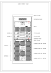
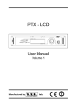
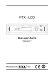
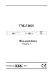
PTX - LCD 8 bit Version User Manual Volume 1 Manufactured by Italy Name File: capitoli_en.p65 Version: 2.3 Date: 18/07/2007 5 H Y LV LR Q + LV WR U \ D a te 2 0 /0 3 /0 1 2 3 /1 1 /0 1 1 1 /0 7 /0 1 1 8 /0 7 /0 7 V e r s io n 2 .0 2 .1 2 .2 2 .3 R eason N e w V e r s io n A U D IN P -D IG U p g ra d e T R D S P U p g ra d e D e s c r ip t io n u p g r a d e o f t h e ju m p e r o n p a n e l c a r d . T R D S P r e m o v a l f r o m 8 b it v e r s io n . S o f t w a r e m e n u u p g ra d e . E d ito r D . C anazza J . B e rti J . B e rti J . B e rti PTX-LCD - User Manual Version 2.3 © Copyright 1998 - 2007 R.V.R. Elettronica SpA Via del Fonditore 2/2c - 40138 - Bologna (Italia) Telephone: +39 051 6010506 Fax: +39 051 6011104 Email: [email protected] Web: www.rvr.it All rights reserved Printed and bound in Italy. No part of this manual may be reproduced, memorized or transmitted in any form or by any means, electronic or mechanic, including photocopying, recording or by any information storage and retrieval system, without written permission of the copyright owner. Notification of intended purpose and limitations of product use This product is a FM transmitter intended for FM audio broadcasting. It utilises operating frequencies not harmonised in the intended countries of use. The user must obtain a license before using the product in intended country of use. Ensure respective country licensing requirements are complied with. Limitations of use can apply in respect of operating freuency, transmitter power and/or channel spacing. Declaration of Conformity Hereby, R.V.R. Elettronica SpA, declares that this FM transmitter is in compliance with the essential requirements and other relevant provisions of Directive 1999/5/EC. PTX-LCD Table of Contents 1. 2. 3. 3.1 3.2 4. 5. 5.1 5.2 5.3 5.4 6 6.1 6.2 6.3 6.4 7. 7.1 7.2 8. 8.1 8.2 9. 10. 10.1 10.2 11. 11.1 11.2 11.3 11.4 11.5 11.6 11.7 11.8 11.9 11.10 Preliminary Instructions Warranty First Aid Treatment of electrical shocks Treatment of electrical Burns General Description Quick Guide Using the encoder Preparation Operation Calibration External Description Front Panel Rear Panel Rear Panel - AUDINP-DIG option Connectors description Operating System Start-up Operating System Technical Specifications Mechanical Specifications Electric Specifications Factory Settings Identification and access to the modules Modules identification Access to the modules Working principles Power supply Audio motherboard Audio Input Coder PLL/Driver card & VCO Card Power amplifier Panel Board CPU card Telemetry board (optional) AUDINP-DIG board (option) Appendix: Component layouts, schematics, bills of material User Manual Rev. 2.3 - 18/07/07 1 3 5 5 6 7 9 9 10 11 12 15 15 16 17 18 21 21 22 37 37 37 41 43 43 44 45 46 47 48 49 51 52 53 54 55 56 i PTX-LCD This page was intentionally left blank ii Rev. 2.3 - 18/07/07 User Manual PTX-LCD 1. Preliminary Instructions This manual is designed to provide a general guide to skilled and qualified personnel, who are aware of the dangers that may arise when handling electric and electronic circuits. It does not aim to provide a complete description of all the safety precautions that must be observed by people who use this or similar equipment. The installation, operation, maintenance and use of this piece of equipment involve risks both for people and the equipment itself, which must be handled only by experienced technicians. R.V.R. Elettronica SpA does not assume responsibility for injuries to persons or damage to items caused by improper use or incorrect usage procedures, whether the users are experienced or not. Users should observe local regulations and fire-prevention rules while installing and using this equipment. WARNING: always disconnect the power before opening covers or removing any part of the equipment. Take appropriate earthing measures to discharge the condensers and high voltage points before doing any maintenance work. WARNING: this equipment may radiate radio-frequency energy, and if it is not installed according to the instructions, may cause troublesome interference to radio communications. Operating this equipment in a residential environment may give rise to radio disturbance; if so, the user may be asked to take appropriate counter measures. R.V.R. Elettronica SpA reserves the right to make modifications to the design and technical specifications of the equipment, and to update this manual without notice. User Manual Rev. 2.3 - 18/07/07 1 / 58 PTX-LCD This page was intentionally left blank 2 / 58 Rev. 2.3 - 18/07/07 User Manual PTX-LCD 2. Warranty The guarantee, which is for 24 (twentyfour) months, is valid for any R.V.R. Elettronica product. On components such as tubes for final amplifiers, the manufacturers guarantee applies. R.V.R. Elettronica extends all transferable original guarantees to its own products. To ensure that servicing is carried out properly and as fast as possible, the work shall be handled by R.V.R. Elettronica; any claims should be sent directly to R.V.R. Elettronica, in accordance with the defined procedures. The warranty does not include: 1 damage while the equipment is being shipped to R.V.R. for repairs; 2 any unauthorized modification or repair; 3 accidental damage, or damage not due to defects in the equipment; 4 nominal damage not accidental; 5 shipping the equipment and insuring it, and replacement of parts or units. Any damage to the equipment caused during shipment must be reported to the transporters and notified in writing on the forwarding receipt. Any difference or damage discovered after delivery must be reported to R.V.R. Elettronica within 5 (five) days from the delivery date. To take advantage of the guarantee, adopt the following procedure: 1 Contact the retailer or dealer where you bought the equipment; describe the problem or fault to check if there is a simple solution. Retailers and Distributors can provide full information on the problems that occur most frequently; they can normally repair the equipment much faster than the manufacturer 2 If your dealer cannot help you, contact R.V.R. Elettronica and describe the problem to them; if necessary, you will be sent authorization with the necessary instructions; 3 When you have received authorisation, return the equipment carriage paid to the address specified. Pack it carefully, if possible in the original packing, and seal the package. Do not return the machine without prior authorization, otherwise it may be returned to you 4 Quote the machines type, model and serial number; attach a written technical diagnosis listing all the problems and faults encountered, and enclose a copy of the invoice. User Manual Rev. 2.3 - 18/07/07 3 / 58 PTX-LCD Replacement of parts under guarantee or spare parts can be ordered from the following address: R.V.R. Elettronica SpA Via del Fonditore, 2/2c 40138 BOLOGNA ITALY Tel. +39 051 6010506 quoting type, model and serial number of the device. 4 / 58 Rev. 2.3 - 18/07/07 User Manual PTX-LCD 3. First Aid Personnel involved in the installation, use, and maintenance of the equipment must be familiar with the theory and practice of first aid. 3.1 Treating electric shocks 3.1.1 If the victim is inconscious Follow the first aid principles described below. Lay the victim down on his back on a rigid surface Free the respiratory tracts by raising the neck and pushing the forehead back (Figure 1). If necessary, check the breathing of the victim opening his mouth. If the victim is not breathing, start artificial respiration immediately (Figure 2): incline the head, close the nostrils, apply your mouth to the victims and make four fast respirations. Figure 1 Figure 2 Check the heart beat (Figure 3); if there is none, start a cardiac massage immediately (Figure 4) pressing the sternum approximately at the centre of the chest (Figure 5). Figure 3 Figure 4 Figure 5 If there is just one person providing first aid, he must adopt a rhythm of 15 compressions and 2 fast respirations alternately. If there are two persons, the rhythm must be 1 respiration and 5 compressions alternately User Manual Rev. 2.3 - 18/07/07 5 / 58 PTX-LCD 3.1.2 3.2 3.2.1 Do not interrupt the cardiac massage during the artificial respiration. Call a doctor as soon as possible If the victim is conscious Cover the victim with a blanket Keep him calm. Loosen the victims clothes and keep him lying down Call a doctor as soon as possible Treating electric burns Large-scale burns and serious cuts Cover the area concerned with a sheet or a clean cloth. Do not break the blisters; remove any fabric and parts of clothing that may be attached to the skin; apply a suitable ointment. Treat the victim depending on the type of accident. Take the victim to hospital as soon as possible. If the arms and legs are injured, keep them raised. If no medical help is available within an hour and the victim is conscious and has not retched, administer a liquid solution of salt and bicarbonate of soda: 1 teaspoonful of salt to every 250ml of water. Get the victim to slowly drink half a glass of the solution, four times, over a period of 15 minutes. Stop the treatment if the victim starts to retch. Do not administer alcoholics! 3.2.2 6 / 58 Less serious burns Apply cold gauze compresses (not iced) using a clean cloth (i.e. as clean as possible). Do not break any blisters; remove any fabric and parts of clothing that may be attached to the skin; apply a suitable ointment. If necessary, dress the victim in clean dry clothes. Treat the victim depending on the type of accident. Take the victim to hospital as soon as possible. If the arms and legs are injured, keep them raised. Rev. 2.3 - 18/07/07 User Manual PTX-LCD 4. General Description The PTX-LCD is a 19" rack-mountable frequency agile FM exciter. Its frequency range spans from 87.5 to 108 MHz in 10 kHz steps, but other frequencies are available on request. The PTX-LCD comes in three versions, depending on its maximum output power: 30 W for the PTX30-LCD version, 60 W for the PTX60-LCD version and 100 W for the PTX100-LCD version, on a 50 Ohm load. The output power can be set anywhere between 0 and the nominal power The PTX-LCD is available either with embedded stereo coder (option code /S) or in MONO/MPX version. The MONO/MPX model can be used for monophonic broadcasting or stereophonic, in conjunction with an external stereo coder. The user interface of thexciter is constituted by a LCD display and a knob (encoder). Using this interface, its possible to read all the working parameters and to adjust the modifiable ones (e.g. power level or working frequency). This exciter offers a number of connectors that can be used to integrate it in complex systems: it is possible to acquire and control external units such as amplifiers, changeover systems, coaxial relays, etc., and to network it with other modulators. The PTX-LCD is designed in a modular way: the different functionalities are performed by modules that are then interconnected either directly (the male connector of one module plugs in the the female connector of another one) or by means of connectors-ended cables. This design allows easy servicing and replacement of the single modules. User Manual Rev. 2.3 - 18/07/07 7 / 58 PTX-LCD This page was intentionally left blank 8 / 58 Rev. 2.3 - 18/07/07 User Manual PTX-LCD 5. Quick Start This chapter gives a concise view of the points that are necessary for the installation of the device. If any item is not completely clear, for example when you use the exciter for the first time, we strongly suggest to read throughly the manual and the description of the operating system. 5.1 Using the encoder The interaction between the user and the exciters control software is performed using the encoder (fig. 5.1). Turn the encoder counterclockwise to move the cursor downwards, to decrease the value of a parameter or to choose an element from a list of possibilities Turn the encoder clockwise to move the cursor upwards, to increase the value of a parameter or to choose an element from a list of possibilities Push the button once to enter in the desired menu, to enter in modification mode or to confirm a choice Figure 5-1 The operations supported by the encoder are: rotation: moves the cursor shown on the display; if you turn the encoder to the left (counterclockwise), the cursor moves downwards, if you turn it right the cursor moves upwards; it also permits to increase or diminish the parameters (turning the encoder left diminishes the parameter, turning it right increases it) or to select an item form a list of options pushing: push the button once when the cursor is on the name of a menu to enter in that menu, push it when the corsor is on the name of a parameter to enter in modification mod (the cursor starts blinking); after the modification of a parameter, push the button to save the new value. After having modified the value of a parameter, the cursor goes on blinking for approximately 30 seconds, waiting for confirmation from the user. If the user doesnt confirm the new value (i.e., the button is not pressed), the device emits a sound to indicate that no modification has been saved; the cursor stops blinking and remains on the selected parameter. User Manual Rev. 2.3 - 18/07/07 9 / 58 PTX-LCD 5.2 Preparation Unpack the transmitter and before any other operation check the unit for any shipping damage and check that all the controls and connectors on the front and rear panels are in good conditions. Check the mains voltage selector on the rear panel: the selected value is indicated by an arrow. If required, extract the selector block levering with a little screwdriver (Fig. 5-2). Rotate the block until the correct printed value corresponds with the arrow, then reinsert it. Figura 5-2 If it has been necessary to change voltage, check the fuse value. The required values are the following: PTX30-LCD 220-240 Volt - 3,16 A (6x30) 110-120 Volt - 6,30 A (6x30) PTX60-LCD 220-240 Volt - 6,30 A (6x30) 110-120 Volt - 10,0 A (6x30) PTX100-LCD 220-240 Volt - 6,30 A (6x30) 110-120 Volt - 10,0 A (6x30) It is also possible to check the integrity of the RF amplifier section fuse: Its value is 4A for the PTX30-LCD version and 8A for the PTX60-LCD and PTX100-LCD versions. Verify that the mains switch on the front panel of the unit is on the OFF position. Connect to the RF output of the exciter a proper load (a dummy load with suitable dissipation power, an antenna, a final amplifier or a combiner) NOTE: When you connect the PTX-LCD to other devices, it is necessary to strictly follow the instructions given by the resepective manufacturers, to avoid damages or danger situations. 10 / 58 Rev. 2.3 - 18/07/07 User Manual PTX-LCD Connect the mains cable to the plug on the rear of the exciter. NOTE: This device shall be correctly connected to ground. Correct grounding is essential both for safety and to reach the rated performances. Connect your source audio (for example the mixer or STL output) to the suitable input connector. Depending on the version, the PTX-LCD offers a number of input choices, L+R, MPX or even digital; see the connectors description for details. 5.3 Operation Switch on the exciter with the mains switch on the front panel. All the STATUS and ALARMS leds are lit on to permit the verification of their good working status. The display than shows some information regarding the exciter. After some seconds, the user is invited by the sound of a buzzer and by a message on the display, to push the encoder if the current settings are not acceptable. If the use pushes the encoder while the message is displayed, the exciter will start in stand-by mode, that is completely working but with RF power disabled. If the encoder is not pushed, the start-up sequence goes on undisturbed. At start-up, the various modifiable parameters will be set as they were before the machine was switched off (i.e., 98.00 % MHz and 0 % are just example values): the current parameters are in fact always stored in non-volatile memory. When the settings are not correct, for example at the first start up of the machine or if for some reason it is necessary to change some parameters before starting to transmit, it is possible to keep the exciter in stand-by mode, as seen above. This operation is necessary only if one wants to modify the devices settings before starting transmitting. Using the menu system provided by the PTX-LCD, described in chapter 7, it is User Manual Rev. 2.3 - 18/07/07 11 / 58 PTX-LCD possible to control all the working parameters of the device. Specifically, before enabling the power output, we suggest to verify and in case to correct according to your needs the fundamental parameters: frequency power audio input level audio input impedance preemphasys kind of audio input (depending on the version, MONO or MPX or MONO, MPX_U, MPX_B, STEREO) if in STEREO mode, verify that pilot tone is enabled If you disabled the power output, it is now possible to activate entering in the main menu, selecting the first item and changing it from OFF to ON. It is any time possible to disable the power output of the PTX-LCD, from the main menu. 5.4 Adjusting The PTX-LCD features some trimmers, accessible from the rear panel, that can be adjusted to the user's needs. these are: two EXT AGC trimmers (FWD and RFL) and the LEVEL ADJ (Fig. 6-2 [16]). The LEVEL ADJ trimmers are used to adjust the modulation level due to the respective input. For audio input, the levels are set via software with 1 dB steps, and the trimmers can be used for fine setting. For SCA input, the levels are only adjusted with the trimmers. The EXT AGC trimmers give to the user the possibility to limit the outout power of the transmitter as a function of the levels of two external analog values that are acquired by the Remote connector. Both trimmers work in the same way: EXT AGC - FWD is connected to pin 10 of the Remote connector, while EXT AGC-RFL is connected to pin 2. If the voltage connected to one of the pins tends to surpass the limit set with the corresponding trimmer, the power emitted by the exciter is reduced until the monitored voltage goes below the fixed limit. These trimmers are mostly useful when the PTX-LCD is part of a transmission system. For example, if the exciter is connected to a final amplifier it is practical to connect to pin 10 a voltage that is proportional to the RF power emitted by the amplifier, and to pin 2 a voltage proportional to the reflected power. In this way, it 12 / 58 Rev. 2.3 - 18/07/07 User Manual PTX-LCD is possible to have constant overall output power even if the amplifiers gain is not constant over the FM range, and to limit the reflected power of the amplifierso that the its protection system doesnt intervene. To adjust the EXT AGC trimmers of the PTX-LCD, procced as described in the following. Perform the connections described in figure 5-3. The connection cable can be supplied on request by R.V.R. Elettronica or be realized by a technician you trust, depending on the pinout of the amplifier you use. PTX-LCD Remote RF Out Telemetry RF In RF Out RF Amplifier Figure 5-3 Switch on the exciter at minimum power. Turn both trimmers completely clockwise. Rise the power emitted by the exciter until on the instrument of the amplifier you read an emitter power level just above the desired threshold. Turn the EXT AGC - FWD trimmer counter-clockwise until you see the power emitted by the amplifier starting to decrease. Decrease the power emitted by the exciter to the minimum. Disconnect the dummy load from the amplifier and substitute it with an unadapted load, so that part of the emitted power is reflected, and set the amplifiers instrument to measure the reflected power. Rise the power emitted by the exciter until on the instrument of the amplifier you User Manual Rev. 2.3 - 18/07/07 13 / 58 PTX-LCD read a reflected power level just above the desired threshold. Turn the EXT AGC - RFL trimmer counter-clockwise until you see the power reflected on the amplifier starting to decrease. At this point, the adjustment of the trimmers is completed. Now you can set on the exciter the output value you desire, without the forward or reflected power of the amplifier surpass the set thresholds. 14 / 58 Rev. 2.3 - 18/07/07 User Manual PTX-LCD 6 External Description This chapter describes the elements of the front and rear panels of the PTX-LCD. 6.1 Front Panel 9 10 11 1 2 3 4 5 6 7 8 Figura 6-1 [1] [2] [3] [4] Operating indicator indicates that the exciter is transmitting indicates that the exciter is under control of an external system lit: the exciter is delivering the set power blinking: the exciter didnt reach the set power for external reasons [5] EXT RF MUTE the exciter is not delivering power because of an externa interlock [6] DISPLAY LCD display, both graphic (240x64 pixels) and text (30x8 characters) [7] ENCODER knob and button to control the management software [8] POWER main switch [9] GENERAL indicates generic fault when lit [10] UNLOCK indicates that the PLL still havent locked on the set frequency when lit [11] SWR indicates that the transmitter is disabled for too much SWR User Manual ON ON AIR REMOTE PWR SET OK Rev. 2.3 - 18/07/07 15 / 58 PTX-LCD 6.2 Rear panel 12 1 13 14 2 3 15 4 16 5 17 18 19 6 7 8 20 9 21 10 11 Figura 6-2 [1] PLUG [2] 24Vdc IN [3] P.A. Fuse [4] INTERLOCK [5] FAN [6] RF Test [7] LEVEL ADJ [8] MPX Unbal [9] SCA1 [10] SCA2 [11] SCA3/RDS [12] FUSE [13] Telemetry [14] RS232 [15] Remote [16] EXT AGC [17] [18] [19] [20] [21] 16 / 58 RF Output Left (mono) Right (MPX) Monitor 19 kHz pilot mains supply plug connectors for external 24 V dc supply (optional). Positive (red) and negative (black) RF power amplifier protection fuse interlock BNC connector.: if the central connector is grounded, the exciter is forced in stand-by mode fan for forced ventilation RF test output 30 dB below emitted level trimmers for adjustment of Left and Right input unbalanced MPX BNC connector, with level adjusting trimmer SCA1 BNC connector, with level adjusting trimmer SCA2 BNC connector, with level adjusting trimmer SCA3/RDS BNC connector, with level adjusting trimmer mains fuse with voltage changer DB25 connector of optional telemetry board DB9 connector for serial communication (direct or via modem) DB15 connector for interfacing with other devices trimmers to adjust the automatic gain control depending on external analog signals N connector for RF output XLR connector for Left/mono input XLR connector for Right/MPX input BNC connector to monitor the composite modulating signal BNC connector for pilot tone output, suitable to synchronize external devices (e.g. RDS coder) Rev. 2.3 - 18/07/07 User Manual PTX-LCD 6.3 Rear panel - AUDINP-DIG option 12 13 14 15 1 2 3 4 11 10 9 8 7 6 5 Analog section [1] [2] [3] [4] Left (Mono) Right (MPX BAL) Monitor 19 kHz pilot [5] [6] [7] [8] SCA3/RDS SCA2 SCA1 MPX Unbal [9] Level IMP ADJ XLR connector for Left/mono input XLR connector for Right/MPX input BNC connector to monitor the composite modulating signal BNC connector for pilot tone output, suitable to synchronize external devices (e.g. RDS coder) SCA3/RDS BNC connector, with level adjusting trimmer SCA2 BNC connector, with level adjusting trimmer SCA1 BNC connector, with level adjusting trimmer Unbalanced MPX BNC connector, with level adjusting trimmer Trimmers for adjustment of Left and Right input Digital section [10] Dig/Analog switch [11] SPDIF [12] TOSLINK [13] Digital Imp. Select [14] Level OUT ADJ [15] AES/EBU User Manual 3.5 JACK connector for external Digital/Analog switch command PIN/RCA unbalanced connector for S/PDIF format audio input connector for fiber optic digital audio input Switch to select the balanced or unbalanced digital audio input Trimmers for adjustment of Left and Right level of converted digital audio signal. XLR balanced connector for AES/EBU format digital audio input Rev. 2.3 - 18/07/07 17 / 58 PTX-LCD 6.4 6.4.1 Connectors description Remote Type: DB15 female 1 9 1 2 3 4 5 6 7 8 9 10 11 12 13 14 15 6.4.2 Ext Rem - Interlock input, if ground the transmitter is disabled Ext Rfl Pwr - analog input for reflected power of an external amplifier GND Analog Input 5 Analog Input 3 Analog Input 1 RLY 2 Out - Digital output. NO relay contact, when the exciter goes from ON to OFF status, the contact has an impulse to ground. If ExPwr is disabled (see 11.7), the meaning of this contact is Power Good: closed = Power Good, open = Alarm GND GND Ext Fwd Pwr - analog input for forward power of an external amplifier Analog Input 6 Analog Input 4 Analog Input 2 GND RLY 1 Out - Digital output. NO relay contact, when the exciter goes from OFF to ON status, the contact has an impulse to ground. If ExPwr is disabled (see 11.7), the meaning of this contact is SWR alarm: closed = OK, open = SWR RS 232 Tipo: DB9 female 1 6 1 2 3 4 5 6 7 8 9 NC TX_D RX_D NC GND +12V NC CTS NC Note: Normally, the PTX-LCD is configured as DCE (Data Communication Equipment) for serial communication. 18 / 58 Rev. 2.3 - 18/07/07 User Manual PTX-LCD 6.4.3 Telemetry (optional board) Type: DB25 female 1 14 6.4.4 1 2 3 4 5 6 7 8 9 10 11 12 13 14 15 16 17 18 19 20 21 22 23 24 25 GND +12V NC relay 1, NC contact relay 2, common contact clock I2C data I2C open collector output (Out in Telemetry menu) telemetry analog input 1 telemetry analog input 3 telemetry analog input 5 telemetry analog input 7 GND GND relay 1, NO contact relay 1, common contact relay 2, NO contact relay 2, NC contact GND GND GND telemetry analog input 2 telemetry analog input 4 telemetry analog input 6 telemetry analog input 8 Left (MONO) / Right (MPX Bal) Type: XLR female 2 1 3 User Manual 1 2 3 GND Signal (+) Signal (-) Rev. 2.3 - 18/07/07 19 / 58 PTX-LCD This page was intentionally left blank 20 / 58 Rev. 2.3 - 18/07/07 User Manual PTX-LCD 7. Operating System The exciter is microprocessor-controlled. The software structure can be divided into a start-up phase and a main cycle. 7.1 7.1.1 Start-up Operating system loading When you switch the exciter on, a window appears on the display, showing some information about the device (Fig. 7-1). Note that "CCIR" in the figure, refers to the set of values that would be used in case of EEPROM error and software reinitialization. Figure 7-1 After about 10 seconds, a new window will show up, while the buzzer emits an intermittent sound (Fig. 7-2). Figure 7-2 While this window is displayed, pushing the encoder will cause RF power to be set "Off": in this way it's possible to change the various parameters before starting transmitting. After 5 seconds, or when the encoder is pushed, the software jumps into its main cycle. 7.1.2 EEPROM Re-initialization At start up, the PTX-LCD software check the coherency of the data stored in the non volatile memory (EEPROM) with respect to the software version. A discrepancy will be detected in case software upgrade. User Manual Rev. 2.3 - 18/07/07 21 / 58 PTX-LCD In such case, the software resets the EEPROM to safe values, that are configurated in the firmaware (EPROM). This behaviour can also be forced by the user: it is sufficient to keep the encoder pushed while switching on the exciter, until the preliminary checks are performed. In such case, In these situations, the following message will be displayed, inviting the user to keep the button pressed to reset the EEPROM, or to release it to keep the EEPROM as it is. Figure 7-3 If the button is released before the count-down expires, the start-up sequence goes on in the standard way. If the button is pushed till the end of the wait time, the EEPROM is stored with a set of default values. Figure 7-4 After pushing the button, the message shown in Fig. 7-5 is displayed for some seconds, after which the software goes on running in the standard way. Figure 7-5 ATTENTION: We strongly suggest not to force the EEPROM re-initialization except in case of real necessity, since this involve the loss of the user configuration. 7.2 Main cycle The menu system of the PTX-LCD can be broken up in a default menu and a set of administration menus. 22 / 58 Rev. 2.3 - 18/07/07 User Manual PTX-LCD Amp/Tm Preset ModPk Menù di scambio (Admin) Predefinito Main Amplifier Power Supply External Power External Status External Frequency Telemetry SCA General Settings Audio Settings Intelligent Automatic Modulation Level Modulation Settings Stereo Settings Figure 7-6 Figure 7-6 depicts the overall flow-chart of the menu system. User Manual Rev. 2.3 - 18/07/07 23 / 58 PTX-LCD 7.2.1 Default menu Figure 7-7 To work on a menu item, turn the encoder to select it and then push the encoder. Depending on the item, it could be possible that a new window is opened or that it will be possible to directly modify the parameter. Activation (On) / deactivation (Off) of RF output power. Otput power reading and setting. The power reading is expressed in Watt, while the setting is expressed as percentage of the maximum output power. Pushing the encoder when the cursor is on this item will put you through the menu that permits to modify the power setting. Figure 7-8 Reflected power reading in watt Reading and setting of the working frequency. Pushing the encoder while the cursor is on this item, will put you through the menu that permits to modify the frequency setting. Figura 7-9 After choosing a new frequency value, the management software will ask you to confirm it (Are you shure? Yes/No). After confirmation pushing the encoder on the choice Yes, the exciter unlocks from the current frequency (the unlock LED is lit) and then locks again on the new frequency. 24 / 58 Rev. 2.3 - 18/07/07 User Manual PTX-LCD Reading and setting of the audio input level. The reported value indicates the audio level that generates 100% modulation. Pushing the encoder while the cursor is on this item, will put you through the menu that permits to modify the audio input level setting. Figure 7-10 The level can be changed between -13 and +14 dBm, at 1 dB steps. On the back of the exciter there are the trimmers to perform fine regulations of the input levels. This status bar reports some settings that can be modified in the administration menus and that will be described in the following of this manual. Ste Audio setting: Stereo/Mono/MPX_U/MPX_B 50u Preemphasys: 0, 25, 50, 75 microsec Cl Clipper function, activated (On) or deactivated (Off) Pl Pilot tone included (On) or excluded (Off) 001 this machines address, comprised between 001 and 256, that is meaningful when the exciter is included in a telemetrized transmission system. Selecting this menu item you will be presented with the menu of time anlaysis of modulation level. Figure 7-11 100 User Manual sampling time of the graphic, selectable out of 100,500 or 1000 millisec; the indicator in the higher part of the display notes the cycle starting point. Each bar corresponds to the modulation level in an interval long as the sampling time Rev. 2.3 - 18/07/07 25 / 58 PTX-LCD INST Visualization method: instantaneous (INST) or average on 300 samples. In instantaneous mode, only the graphic visualization is active. In 300 mode, at the end of the analysis (300 x sample time) the values M, S, % and K will be displayed M Percent value of the mean modulation during the analysis S Part of the modulation surpassing 100% % Percentage of modulation peaks on the 300 samples K S times % RESET Pushing the encoder on this item will refresh the graphic EXIT Pushing the encoder on this item will return you to the default menu Selecting this item of the default menu and pushing the encoder will present you the peak modulation analysis menu. Figure 7-12 This graphic gives a visualization of the distibution af peak modulation levels. With this graphic, you can get a good idea of the modulation level reached during the working time. Each horizontal bar corresponds to the fraction of the time in which the modulation had that percent value. The percent value can be read on the meter bar an the left of the graph. 100 sampling time of the graphic, selectable out of 100,500 or 1000 millisec. INST Visualization method: instantaneous (INST) or average on 300 samples. In instantaneous mode, only the graphic visualization is active. In 300 mode, at the end of the analysis (300 x sample time) the values M, S, % and K will be displayed M Percent value of the mean modulation during the analysis S Part of the modulation surpassing 100% % Percentage of modulation peaks on the 300 samples K S times % RESET Pushing the encoder on this item will refresh the graphic EXIT Pushing the encoder on this item will return you to the default menu 26 / 58 Rev. 2.3 - 18/07/07 User Manual PTX-LCD Selecting this menu item and pushing the encoder you will access the window that permits to reset the exciter to the factory settings. Figure 7-13 As indicated by the window text, keeping the encoder pressed for two seconds will reset the exciterand a start-up procedure analogous to that performed at switch-on will follow. The preset values are the same used for EEPROM reinitialization (see chapter 7.1.2 and chapter 9), except for the working frequency, that remains set as the current one. If you want to skip the menu, just breafly push the encoder. Selecting this menu item and pushing the encoder will visualize the window that permits to access all the administration menus. 7.2.2 Administration menu This menu is divided in 13 submenus (12 for the MONO/MPX version of the PTX-LCD) The window dispalyed to the user as soon as he entered in this menu warns to proceed only after reading the technical manual: Figure 7-14 The windows of the administration menu are subdivided in three parts. on the left, the bar indicator shows the instantaneous modulation level the cetral part displays the submenu content, that can be just informative or modifiable depending on the menu the right part is a navigation bar perrmitting the user to go from a submenu to the other Turning the encoder, the cursor moves over the indicators of the different submenus, while in the central part of the window their contents is displayed in turn. User Manual Rev. 2.3 - 18/07/07 27 / 58 PTX-LCD If you push the encoder while the cursor is on the name of a submenu, and if this one contains modifiable parameters, the cursors enters in the central part of the window, permitting to edit thos modifiable parameters. Each of the menus of this kind contains an EXIT item: pushing the encoder while the cursor is on EXIT will put you back in navigation mode. 7.2.2.1 Main Figure 7-15 28 / 58 RF Activation (On) / deactivation of RF power output FPwr Reading and setting of the output power. The power reading is expressed in Watts, the setting value in % of the maximum power. If one pushes the encoder when the cursor is on this item, the measuring unit changes from W to %, and turning the encoder he will be able to set the desired value. Pushing the encoder again will store the new setting. RFPwr Reflected power reading in Watts Freq Working frequency. Pushing the encoder when the cursor is on this item will give the possibility to change the working frequency turning the encoder. Please note that when the encoder will be pushed to store the new frequency, the software will ask for its confirmation(Are you sure?). If you select Yes and push the encoder, the new frequency will be set, wile pushing the encoder on No it will be aborted. VCO Control voltage applied to VCO in Volt Rev. 2.3 - 18/07/07 User Manual PTX-LCD 7.2.2.2 Ampli This menu is for information only, no value can be modied, since they show current, voltage and temperature af the amplifier section Figure 7-16 7.2.2.3 IN.V Input voltage to the power supply PA.V Voltage of the final stage of the amplifier PA.I Current of the final stage of the amplifier TEMP temperature of the amplifier. Suppl This menu is for information only; it displays to the user the different voltages produced by the power supply: Figure 7-17 +15 general supply voltage of the circuits audio, pll, coder; it is reduced to 8 V on the main audio board. +15 supply voltage of the CPU panel +5 power supplys digital circuits voltage -12 general negative supply voltage LAMP supply voltage of the display lamp, typical 13 V +5 CPU supply voltage User Manual Rev. 2.3 - 18/07/07 29 / 58 PTX-LCD 7.2.2.4 ExPwr External amplifier control menu This menu can be available or not depending on the jumpers configuration (see 11.7.1). The use of this menu requires the presence of a power amplifier with suitable characteristics (it has to be activable and deactivable opening a contact, and it has to give back the readings of the forward and reflected power as a couple of voltage proportional to those values). Figure 7-18 7.2.2.5 PWR status indicator, related to the status of PTX-LCD (MAIN menu) FPWR forward power of the amplifier, percentage RPWR reflected power of the amplifier, percentage ExSts This menu monitors the input voltages on the telemetry connectors. This menu can be available or not depending on the jumpers configuration (see 11.7.1). Figure 7-19 30 / 58 V1 Voltage on pin 6 of the Telemetry connector (5 V max.) V2 Voltage on pin 13 of the Telemetry connector (5 V max.) V3 Voltage on pin 5 of the Telemetry connector (5 V max.) V4 Voltage on pin 12 of the Telemetry connector (5 V max.) V5 Voltage on pin 4 of the Telemetry connector (5 V max.) V6 Voltage on pin 11 of the Telemetry connector (5 V max.) Rev. 2.3 - 18/07/07 User Manual PTX-LCD 7.2.2.6 ExFrq This menu is used to set the alternative frequencies that shall be used when the exciter is used as backup in a N+1 system. This menu can be available or not depending on the jumpers configuration (see 11.7.1). Figure 7-20 7.2.2.7 0 default frequency 1-6 transmitters 1-6 working frequencies 7-9 reserved Telem This menu, that is alway activated, shows the status of the optional telemetry board. Figure 7-21 If the optional board is not present, the displayed values are not applicable. If the board is there (the DB 25 connector on the rear panel is also present) the meaning of the different fields is the following: T1 voltage on pin 9 of the telemetry card connector T2 voltage on pin 22 of the telemetry card connector T3 voltage on pin 10 of the telemetry card connector T4 voltage on pin 23 of the telemetry card connector T5 voltage on pin 11 of the telemetry card connector T6 voltage on pin 24 of the telemetry card connector T7 voltage on pin 12 of the telemetry card connector T8 voltage on pin 25 of the telemetry card connector User Manual Rev. 2.3 - 18/07/07 31 / 58 PTX-LCD 7.2.2.8 R1 activation/deactivation of relay 1 R2 activation/deactivation of relay 2 VB battery supply voltage (only with option 24 volts). OUT open collector service output SCA In this menu one can read the modulation level due to SCA and RDS input Figure 7-22 In the PTX-LCD there are three input connectors for subcarrier signals, called SCA1, SCA2 and RDS. This menu displays the modulation levels (percentage and kHz) for each of them 7.2.2.9 GenSt General settings menu Figure 7-23 Uart Adr address (serial port and IIC protocol) of this device, selectable between 1 and 200. If the exciter is not networked in a transmission system, this value shall be set to 1 Baud Rate Baud rate of the serial port 32 / 58 MODEM Configures the PTX-LCD for the use of a modem (present) or for direct cable connection JUMP Shows the jumpers setting. The symbol X means that a jumper is closed, the symbol - indicates its open. For the meaning of the jumpers setting see chapter 10.7.1. Rev. 2.3 - 18/07/07 User Manual PTX-LCD 7.2.2.10 Auset Audio settings: channels activation and level adjusting. Figure 7-24 MONO/L audio level setting for the MONO input channel (left for the stereo version). It can be set with 1 dB steps between -13 and +14 dBm. If this parameter is set to X dBm, the exciter generates 75 kHz modulation for X dBm input MPX/R audio level setting for the MONO input channel (left for the stereo version). It can be set with 1 dB steps between -13 and +14 dBm.. The meaning is the same of MONO/L MONO/L software switch to activate/deactivate the MONO channel (left for the stereo version) MPX/R software switch to activate/deactivate the MPX channel (right for the stereo version) When the exciter is in STEREO mode (BdSet menu), the levels on both channels are forced to the same value 7.2.2.11 IAMLC Intelligent Automatic Modulation Level Control. Figure 7-25 The IAMLC functionality provided by PTX-LCD adjusts the modulation level by adaptation of the input level, without the use of limitation or compression. When the average modulation level surpasses the maximum threshold for a time interval exceeding the maximum hysteresis time that has been set, the input level is attenuated by 1 dB. In the same way, when the average modulation level goes below the minimum threshold for a time interval exceeding the minimum hysteresis time that has been set, the input level is increased by 1 dB. User Manual Rev. 2.3 - 18/07/07 33 / 58 PTX-LCD Both the attenuation and the increase that IAMLC is allowed to introduce, have limits that can be set by the user. The elements of this menu are the following: IAMLC Enable or disable the function Mod Minimum and maximum thresholds for the intervention of IAMLC Ist Intervention time related to the minimum and maximum thresholds Att Maximum attenuation and increase IAMLC is allowed to introduce The following table suggests the settings of this function for different kinds of radio programs Radio Program Mod Min Mod Max Ist Min Ist Max Att Min Att Max Dance 75 % 100 % 10 s 1s -3 dBm +6 dBm Pop, rock 30 % 100 % 20 s 0,5 s -3 dBm +6 dBm Electronic 50 % 100 % 10 s 1,5 s -3 dBm +3 dBm Jazz 40 % 100 % 5s 0,5 s -3 dBm +6 dBm Classical 20 % 92 % 30 s 0,5 s -4 dBm +10 dBm Talk show 40 % 85 % 30 s 1s -3 dBm +14 dBm The best results with this function will be obtained investing some time in experimentation with your own radio programs: use the man MODPK to check your average modulation level. Adjust the input level from the main menu so that the average modulation level is the nearest to 100%. Set the IAMLC parameters as suggested by the table, and adjust them so that the function is not activated too often. Consider the fact that the intervention of the function stops when the average modulation level goes between the minimum and maximum thresholds. The use of the clipper circuit (BdSet menu) helps in the limitation of the modulation peaks above 100%, though introducing a certain aomunt of distorion. Think about your possible need for this function, depending on your radio program. it aiuta a limitare i picchi superiori al 100 % di modulazione, introducendo però una certa quantità di distorsione. Valutare la necessità di questo limitatore in funzione del proprio programma musicale. Figure 7.26 shows an example of modulation level evolution when the IAMLC function is activated. 34 / 58 Rev. 2.3 - 18/07/07 User Manual PTX-LCD Average modulation level Ist Max Ist Max 1 dB 1 dB Mod Max Ist min Mod min Time Figure 7-26 7.2.2.12 BdSet Modulation type configuration Figure 7-27 Mode transmission mode selector: MONO, MPX_U (MPX unbalanced BNC input), MBX_B (MPX balanced XLR input), STEREO. The latter option is active only for stereo machines. Preemph Preemphasys setting, 0, 25, 50 o 75 ms. Preemphasys works on the Right and Left channels in stereo mode and on mono input. MPX input are not touched by this setting. Clipper Activation/deactivation of the modulation limiter. It limits the modulation to 81.5 kHz for input signals 6 dB above the reference input level Imped Balanced audio input impedance, selectable between 600 or 10k Ohm. Scale Graphic scale of the VU meter. It can be set to 1:1 (normal visualization) or 1:10 (multiplied by 10, useful when low modulation levels have to be measured) User Manual Rev. 2.3 - 18/07/07 35 / 58 PTX-LCD 7.2.2.13 StSet Stereo coder board configuratio menu (available if the stereo option is installed) Figure 7-8 Pilot0 Pilot tone phase (not available) 36 / 58 Pilot Activation/deactivation of the pilot tone (can be useful for certain measurements) Chan0 Phase of the right channel; it can be set to 0 or 180 (signal mirroring, useful for example to measure the Sub to Main parameter) Rev. 2.3 - 18/07/07 User Manual PTX-LCD 8. Technical Specifications 8.1 Mechanical Specifications Panel size Depth Weight Temperature range 8.2 PTX30 PTX60 PTX100 483 mm (19) x 88 mm (3 1/2) (2 HE) 344 mm (26 1/2) 13 Kg 15.5 Kg 15.5 Kg -10 °C ÷ 50 °C Electrical Specifications General RF output power PTX30LCD: PTX60LCD: PTX100LCD: RF output connector RF output impedance Frequency range Frequency setting Frequency stability Modulation type Sopressione di spurie e armoniche Modulation capability Residual async AM Residual sync AM Intermodulation distortion Power supply Power consumption PTX30LCD PTX60LCD PTX100LCD Input Left/Mono and Right/MPX MPX Input impedance Input level Preemphasys SCA/RDS input SCA input impedance User Manual selectable: 0-30 W adjustable 0-60 W adjustable 0-100 W adjustable type "N" 50 Ohm 87.5 MHz ÷ 108 MHz direct, via software ±1ppm from -10°C to 50°C Direct carrier modulation meets or exceeds FCC e CCIR rules (typical 85 dB) meets or exceeds FCC e CCIR rules (typical 240khz MPX or Mono, 210 KHz Stereo) -70 dB or less wrt. 100% AM, no deemphasys -60 dB or less wrt 100% AM, 75 kHz FM at 400Hz, no deemphasys Less than 0.1% (typ. 0.05%) measured with a 3.18KHz square wawe, 15KHz sinusoidal wawe and 100% modulation 110÷130 V, 50÷60 Hz 198÷250 V, 50÷60 Hz 120 VA ca. 200 VA ca. 300 VA ca. Type XLR female, balanced or unbalanced Type BNC, unbalanced 10 KOhm or 600 Ohm, software selectable -13 dBm ÷ +14 dBm software adjustable in 1 dB steps, fine adjusting with trimmers 0 25 us 50 us (CCIR) 75 us (FCC) 3 BNC connectors, unbalanced 10 KOhm Rev. 2.3 - 18/07/07 37 / 58 PTX-LCD SCA input level SCA amplitude-frequency response Crosstalk from subcarrier 67KHz on main or stereo channel Crosstalk from subcarrier 92KHz on main or stereo channels Output MPX monitor: MONO operation FM S/N Amplitude/frequency response Total Harmonic Distortion (THD) Intermodulation distortion MPX operation Composite FM S/N MPX frequency/amplitude response MPX THD Intermodulation distortion Stereo separation Stereo Operation Stereo FM S/N Audio amplitude/frequency response Total Harmonic distortion Intermodulation distortion Stereo separation Remote connections Interlock I2C interface 38 / 58 70 dB 0 dBm for FM 75KHz minimum load 600 Ohm 1 Vpp minimum load 4.7 KOhm -30 dB wrt RF 50 Ohm impedance Pilota tone 19 KHz RF Test Remote connector -20 dBm ÷ +10 dBm, trimmer adjustable ± 0.2 dB, from 40 KHz to 100 KHz 65 dB > 82dB (90 dB typical) wrt 75KHz measured in 20 Hz ÷ 20 KHz band with 50 us deemphasys, RMS detector ± 0.5 dB, 20Hz ÷ 15Khz < 0.02% < 0.02% measured with 1 KHz and 1.3 KHz tones, 1:1, 75 kHz modulation > 82dB (90 dB typical) wrt 75 kHz measured in 20 Hz ÷ 100 kHz band with 50 us deemphasys, RMS detector ± 0.05 dB, 20 Hz ÷ 53 KHz ± 0.2 dB, 53 KHz ÷ 100 KHz < 0.02% < 0.02% measured with 1 kHz e 1.3 kHz tones, 1:1, 75 kHz FM > 50 dB (typical 60dB) > 82dB (90 dB typical) wrt 75 kHz measured in 20 Hz ÷ 100 kHz band with 50 us deemphasys, RMS detector ± 0.5 dB, 20 Hz ÷ 15 KHz < 0.03% < 0.03%, measured with 1 KHz and 1.3 KHz tones, 1:1, 75 kHz modulation > 50 dB (typical 60 dB) DB15 female; includes: FWD and RFL input for external AGC 6 digital/analog input 2 relay output BNC type, for power output deactivation Rev. 2.3 - 18/07/07 User Manual PTX-LCD Serial interface Optional telemetry board Options /03 /08 /AUDIOINP-DIG AUDIOINP-DIG D/A converter Sampling frequency Data formats Digtal inputs Emergency switch User Manual DB9 female RS232, DTE or DCE selectable RS485 (Optional) DTE or DCE selectable DB25 female 8 analaog/digital input 2 digital output 1 I2C serial interface External 24V battery Telemetry interface Digital audio input interface 24 bit From 32 to 96 KHz S/PDIF, AES/EBU, IEC958 and EIAJ CP340/ 1201 1 Unbalanced for coaxial cable with PIN/ RCA connector (S/PDIF) 1 TOSLINK fiber optic 1 XLR balanced female connector (AES/ EBU) 3.5mm JACK; shorted to ground forces the selecion of analog input Rev. 2.3 - 18/07/07 39 / 58 PTX-LCD This page was intentionally left blank 40 / 58 Rev. 2.3 - 18/07/07 User Manual PTX-LCD 9. Factory settings Each time a working parameter of PTX-LCD is changed by the user, the new value is stored in the working configuration and saved in a non volatile memory. In this way, at switch-on the exciter is configured exactly as it was when it was last switched off. When shipped, the exciter can be configure at customers requests (for example if it is part of a transmission system with working frequency and modes specified in the order), or it can have a default configuration. The default configuration of the PTX-LCD is determined by the setting of a group of internal jumpers. At start-up, the name of the default configuration is shown on the display of the device (see 7.1). The possible configurations are the following: CCIR Parameter Power output Minimum frequency Maximum frequency Frequency steps Preset frequencies Menu Default / / / Admin-ExFrq Value On 87.5 MHz 108.0 MHz 10 kHz 87.5, 90.0, 92.0, 94.0, 96.0, 98.0, 100.0, 102.0, 104.0, 106.0 MHz Power Default 0% Input level Mono/L Admin->AuSet->Mono/L X dBm 0 dBm Input level MPX/R Admin->AuSet->MPX/R X dBm 0 dBm Input status Mono/L Admin->AuSet->Mono/L On Input status MPX/R Admin->AuSet->MPX/R On Preemphasys Admin->BdSet->Preenph 50 μs Clipper Admin->BdSet->Clipper Off Audio Mode Admin->BdSet->Mode Stereo (If stereocoder present) MPX (If stereocoder not present) Pilot Tone Admin->StSet->Pilot On (If stereocoder present) Phase shif between channels Admin->StSet->Chan 0 (If stereocoder present) FCC Configuration as CCIR, with: Parameter Preemphasys Audio Mode User Manual Menu Value Admin->BdSet->Preenph 75 μs Admin->BdSet->Mode Stereo (If stereo coder present) Mono (If stereo coder not present) Rev. 2.3 - 18/07/07 41 / 58 PTX-LCD OIRT Configuration as CCIR, with: Parameter Minimum frequency Maximum frequency Preset frequencies Audio mode Menu / / Admin-ExFrq Value 66.0 MHz 74.0 MHz 66.0, 67.00, 68.00, 68.00, 69.00, 70.00, 71.00, 72.00, 73.00, 74.00 MHz Admin->BdSet->Mode Stereo (If stereo coder present) Mono (If stereo coder present) JAPAN Configuration as CCIR, with: Parameter Minimum frequency Maximum frequency Preset frequencies Modo di funzionamento Menu / / Admin-ExFrq Value 76.0 MHz 90.0 MHz 76.0, 78.0, 80.0, 82.0, 83.0, 84.0, 85.0, 86.0, 88.0, 90.0 MHz Admin->BdSet->Mode Stereo (If stereo coder present) Mono (If stereo coder not present) ITALIA Configuration as CCIR, with: Parameter Minimum frequency Maximum frequency Frequency step Preset frequencies Clipper Modo di funzionamento Menu / / / Admin-ExFrq Value 87.6 MHz 107.9 MHz 100 kHz 87.6, 90.0, 92.0, 94.0, 96.0, 98.0, 100.0, 102.0, 104.0, 106.0 MHz Admin->BdSet->Preenph On Admin->BdSet->Mode Stereo (If stereo coder present) Mono (If stereo coder not present) C.S.I Configuration as CCIR, with: Parameter Minimum frequency Maximum frequency Preset frequencies Menu / / Admin-ExFrq China Configuration as CCIR, with: Parameter Minimum frequency Maximum frequency Preset frequencies 42 / 58 Menu / / Admin-ExFrq Value 100.0 MHz 108.0 MHz 100.0, 100.5, 100.1, 101.5, 102.0, 103.0, 104.0, 105.0, 106.0, 108.0 MHz Value 87.0 MHz 108.0 MHz 87.0, 90.0, 92.0, 94.0, 96.0, 98.0, 100.0, 102.0, 104.0, 106.0 MHz Rev. 2.3 - 18/07/07 User Manual PTX-LCD 10. Identification and access to the modules 10.1 Modules identification Figure 10-1 shows the upper view of the internal of the exciter. The components are described below. 1 7 8 2 3 9 4 10 5 6 11 Figure 10-1 [1] [2] [3] [4] [5] [6] [7] [8] [9] [10] [11] User Manual Audio input board Stereo coder or mono board RF power amplifier Audio mother board PLL & VCO board CPU board Power supply Transformer Switching power supply Heatsink Panel board - display Rev. 2.3 - 18/07/07 43 / 58 PTX-LCD 10.2 Access to the modules ATTENTION: opening the device, points with dangerous voltages and currents are exposed. Always disconnect the mains supply before removing the covers or taking away any part of the piece of equipment. Remove all the screws on the upper cover of the exciter. After taking away the cover, identify with the help of figure 10-1, the components of the exciter. To remove the coder boards (stereo and mono) and PLL, it is sufficient to remove the nuts that fix them to their hexagonal supports. Note that in the lower parts of both boards there are strip line connectors that are plugged into the audio motherboard. To remove the input audio board (that is united with the audio connector board and the right part of the rear panel of the exciter), unscrew the four nuts that fix the board to the hex supports on the audio mother board.ore), the five screws on the rear panel (figure 10-2) and the three screws in the bottom part that fix the support of the connectors. 3 1 2 4 5 Figure 10-2 The RF power amplifier, joined to its heatsink, is kept in place by three screw on the bottom of the exciter. The screws are fastened in the heatsink, and its sufficient to remove them to release the amplifier. To remove the power supply and the switching power supply, the same procedure has to be followed, i.e. the screws that fix the heatsinks to the bottom of the machine have to be removed. Note that the interlock connector, soldered to the power supply, is fixed to the rear panel with a nut that has to be removed to release the power supply. Finally, the panel board and the CPU board are simply fixed tu hex supports on the front panels with nuts. To remove these boards, we suggest to release the front panel of the exciter from the chassis. 44 / 58 Rev. 2.3 - 18/07/07 User Manual 1 2 3 4 DB9 CN1 A MAINS VOLTAGE JP4 JP3 F1 FUSE CT CT1 240V 220V 120V 110V BACKLIGHT LAMP FRONT PANEL CARD JP1 JP1 JP2 TR3S TR1 B JP10 JP11 JP9 BACKLIGHT LED LAMP STRIP 90 PIN 6 PIN MASCON FLAT 9 XLR CN7 XLR CN6 B BNC EXTERNAL REMOTE CN4 STRIP 26 PIN STRIP 16 PIN AUDIO INPUT CONNECTOR CARD JP5 CN3 JP1 DB15 C 1 CN5 CN06MM FAN FAN1 F2 FS5_20 PFT630 PF1 2 CN2 JP3 FLAT 16 JP6 CN10MM 1 2 3 4 5 6 D CN05MM 5 4 3 2 1 CN02MM 2 1 CN05MM 5 4 3 2 1 CN02MM 2 7 8 D JP1 1 STRIP 26 9 FLAT 16 JP4 10 MOTHER BOARD AUDIO JP1 STRIP 34 PIN JP1 AUDIO INPUT CARD POWER SUPPLY CARD JP2 TELEMETRY CN06MM 1 2 3 4 5 6 FLAT 26 FLAT 34 JP5 JP3 JP2 C 4 MAINS SWITCH SW1 DISPLAY CPU CARD ENCODER RS-232 BNC BNC BNC BNC BNC STEREO CODER CARD OR MONO / MPX CARD CN9 CN8 CN4 CN3 CN2 240 220 Rev. 2.3 - 18/07/07 3 120 User Manual 2 100 A JP2 JP1 JP2 JP1 CN1 RG58 CABLE CN1 PLL CARD SWITCHING POWER SUPPLY #2 Date: Size A2 Title Block diagram Document Number PTX LCD E Sheet 1 CN3 CN2 R.V.R. Elettronica S.r.l. (BO) R.F. POWER AMPLIFIER SWITCHING POWER SUPPLY #1 CON-PA CARD JP1 TP13 TP12 TP14 TP15 TP11 TP1 TP2 TP3 TP4 TP5 V.C.O. CARD E of BNC N-type 1 Rev 1 1 2 3 4 PTX-LCD 11 Working principles Figure 11-1 gives an overview of modules and connections composing the PTX-LCD. 1 5 6 Figure 11-1 In the following you will find a short description of the functionalities of each module. 45 / 58 PTX-LCD 11.1 Power supply The power supply is composed of two sections. The first one is dedicated to the finale amplifier. It is a switch mode power supply fastened to a heat sink (Fig. 10-1 9). In the 30 W version, there is a second switching power supply of the same kind under the first one. Figure 11-2 The second section (Fig. 11-3) is the board fixed to a heatsink in the central part of the exciter (Fig 10-1 7). This board contains the power supply for the different boards of the exciter (audio, CPU, ...), the section that manages the analog input from the Remote connector and the Automatic Gain Control for the output power level management. R98 R30 R51 R39 R35 R35 D52 D53 D58 D54 D55 D57 JP6 R17 R18 Figure 11-3 46 / 58 Rev. 2.3 - 18/07/07 User Manual PTX-LCD 11.1.1 Adjustings, settings and indicators The switching mode power supply doesnt need any adjusting, while the power supply board features a number of indicators and adjustable components. D52 D53 D54 D55 D57 D58 RV1 R17 R18 R30 R35 R39 R51 R98 JP6 11.2 lit: fault of the power amplifier fuse lit: fault of PF1 fuse lit: voltage +5V OK lit: voltage +15V OK lit: voltage -12V OK lit: power amplifier power supply OK adjustment of the temperature sensor adjustment of the level for external AGC adjustment of the level for external AGC adjustment of the measurement of PA current adjustment of the maximum PA current adjustment of the measurement of forward power adjustment of the measurement of reflected power adjustment of the measurement of driver stage current 1-3, 2-4 the Remote connector pins are used as analog input 3-5, 4-6 the Remote connector pins are used for I2C communication Audio motherboard This board (Fig 11-4) is the interface between the audio section boards and the PLL with the other modules of the exciter. The audio motherboard is in the lower left part of the exciter (Fig. 10-1 4). It contains the connectors on which the other boards are directly plugged in. This module also contains the circuit mixing MPX signals and SCA/RDS subcarriers. D4 D5 D6 D2 JP8 Figure 11-4 User Manual Rev. 2.3 - 18/07/07 47 / 58 PTX-LCD 11.2.1 Adjustments, settings and indicators D2 D4 D5 D6 JP8 11.3 lit: no audio lit: supply voltage OK lit: supply voltage OK lit: supply voltage OK factory setting, please dont change Audio input The audio input section is on the rear part of the exciter and is directly connected to the audio motherboard using a strip-line connector. It is composed of two boards coupled in a L shape and fastened to the part of the rear panel that hosts the audio connectors. The first board (Fig. 11-5) contains the trimmers to adjust the levels and the filters for each input channel. The second board (Fig. 11-6) contains the level regulations and the switches for the software-based audio configuration. Figure 11-5 After the necessary processing (filtering, level regulation, selection), the audio input section passes the signals to the audio motherboard that route them to the coder card. 48 / 58 Rev. 2.3 - 18/07/07 User Manual PTX-LCD D2 D1 JP8 JP11 JP12 JP3 JP10 JP2 JP9 Figura 11-6 11.3.1 Adjustments, settings and indicators D2 D1 JP3 JP2 JP8 JP11 JP10 JP9 JP12 RV7 11.4 On: negative power supply voltage present On: positive power supply voltage present 3-5, 4-6, 9-11, 10-12 no attenuation con channel L 1-3, 2-4, 7-9, 8-10 12 dB attenuation on channel L as JP3, for channel R 1-2 no gain on channel SCA2, 2-3 20 dB gain 1-2 input impedance for channel MPX_U 50 Ohm, 2-3 10 kOhm 1-2 no gain on channel SCA3, 2-3 30 dB gain 1-2 no gain on channel SCA1, 2-3 20 dB gain 3-5, 4-6 no attenuation on channel MPX 1-3, 2-4 12 dB attenuation on channel MPX Adjustment of the MPX monitor output Coder The coder card is located above the audio motherboard between the audio input section and the PLL/Driver board. Two versions of this boards are available, the Stereo one (Fig. 11-7) and the Mono/MPX one(Fig. 11-8). The only difference between a Stereo PTX-LCD and a Mono/MPX one resides in the kind of coder module. On this board, depending on the version, there are the low-pass filters, the preemphasys circuits, the stereo coder and the clipper circuit, that can be included or excluded via software. User Manual Rev. 2.3 - 18/07/07 49 / 58 PTX-LCD The function of the Clipper circuit, that in some countries is manatory, is to limit the modulation level even for audio input levels above the nominal value. R40 C4 R33 R17 R39 R16 R15 C2 R11 Figure 11-7 RV1 RV2 RV3 D2 D1 D3 Figure 11.8 11.4.1 Adjustments, settings and indicators Stereo Coder C2 C4 R11 R15 R16 R17 R33 50 / 58 Pilot tone phase Pilot tone frequency Output level stereocoder card Pilot tone level stereo separation optimization - left channel stereo separation optimization - right channel clipper circuit intervention threshold Rev. 2.3 - 18/07/07 User Manual PTX-LCD R39 R40 clipper symmetry adjustment 38 kHz subcarrier suppression optimization Mono/MPX board LP1 LP2 RV1 RV2 RV3 D1 D2 D3 11.5 Low pass filter 1 Low pass filter 2 Mono level Board output level (modulation) clipper circuit intervention threshold positive power supply voltage presence negative power supply voltage presence clipper intervention signalling PLL/Driver card & VCO Card The PLL/Driver board (Fig. 11-9) is placed on the left part of the PTX-LCD (Fig. 10-1 5) and is directly connected to the audio motherboard. The digital PLL module is composed by a high stability temperature-controlled oscillator and by the digital circuit doing the division and the comparison of the working frequency. The oscillator generates a 10 MHz frequency divided by a fixed 1 kHz signal. This signal is routed to the digital comparator/divider circuit that compares it to the signal generated by the VCO dived depending on the exciters working frequency. The output of the comparator is the AFC signal that is applied to the varicap diodes on the VCO board and added to the audio signal coming from the coder card. The Voltage Controlled Oscillator generates the RF signal that is aplified up to around 300mW (25dBm), that is the level required to drive the R.F. Power Amplifier. Nota: The VCO is cointained in a silvered brass box fixed on the PLL & Driver board. User Manual Rev. 2.3 - 18/07/07 51 / 58 PTX-LCD JP5 D2 RV1 JP3 JP2 Figure 11-9 11.5.1 11.6 Adjustments, settings and indicators D2 RV1 JP2 JP3 JP5 On: PLL unlocked bias adjustment factory settings - do not change factory settings - do not change factory settings - do not change Power Amplifier Two version of the RF power amplifier are available, 30 and 60/100W. This section is placed in the central part of the device (Fig. 10-13), is fixed to a heatsink and contained in a metal box completely shielding it. The RF signal coming from the PLL/Driver card is first amplified by the pilot stage (MRF237 working in class C) up to 1.5 W, and then passed to the final stage (MRF315) that amplifies it to 30W. In case of 60/100W the RF signal coming from the PLL/Driver card is first amplified by the pilot stage (2xBFR540 and BLF244), then passed through the final stage (SD1480) to obtain an amplified power of 60 or 100W. The amplified signal is filtered by a low-pass filter to reduce the harmonic emissions below the permitted levels. A directional coupler inside the final amplifier gives the readings of forward and reflected power, that are then sent to the power supply section to be controlled. 52 / 58 Rev. 2.3 - 18/07/07 User Manual PTX-LCD A -30 dB test probe is available on a BNC connector on the rear panel of the exciter, just under the RF output connector. Figure 11-10 - 30W Figure 11-11 - 60/100W 11.7 Panel Board This card is located in the front end of the device and provides an interface between the CPU card and the remaining PTX-LCD cards. This card handles all signals from/to LCD, Encoder, LED Indicators, Power Supply Card, Audio Mainboard and external telemetry card, in other words, all input/output signals of the CPU card. JP8 Figure 11-12 User Manual Rev. 2.3 - 18/07/07 53 / 58 PTX-LCD 11.7.1 Adjustments, settings and indicators JP8 Position of panel card jumpers. The software denotes jumper positions as follows (1 signifies a closed jumper, 0 open jumper, X any position): -XPS 0 1 0 1 X -XPS 0 0 1 1 X -XPS X X X X 0 -XPS X X X X 0 -XPS X X X X 0 X X X X 1 0 0 1 0 0 X X 1 1 0 X X 0 0 1 X X X X 1 0 0 1 1 1 X X 1 1 1 0HDQLQJ ExPwr, ExSts and ExFrq menu disabled ExPwr and ExSts menu enabled, ExFrq menu disabled ExPwr and ExSts menu disabled, ExFrq enabled ExPwr, ExSts and ExFrq disabled Default parameters set in case of exciter reset: CCIR for PLL at 10MHz Default parameters set in case of exciter reset: FCC Default parameters set in case of exciter reset: OIRT Default parameters set in case of exciter reset: Japan Default parameters set in case of exciter reset: Italy Default parameters set in case of exciter reset: CSI Default parameters set in case of exciter reset: China Reserved for future applications In case of ExFrq enabled is necessary to modify the jumper JP6 on power supply, as indicated in the following figure, in order to enabled the alternatives frequencies that shall be used when the exciter is used as backup in a N+1 system. 11.8 CPU board The CPU board is on the front part of the device, fixed to the panel board. This board is the heart of the transmitter, since it manages and elaborates all the information coming from the other boards and possibly from other devices via the serial interface or the telemetry board. The main characteristics of the CPU board are: 54 / 58 Microprocessor: 80C552 Eprom size: 64KBytes Static RAM size: 32KBytes Communication interfaces: RS232-RS485 and I2C Bus EEPROM size: 256KBytes Self-diagnosys Leds: 9, red Rev. 2.3 - 18/07/07 User Manual PTX-LCD D1-D9 JP2 JP8 Figure 11-13 11.8.1 Adjustments, settings and indicators D1-D9 On: communication activity JP1 1-2, 3-4 serial port set as DCE 5-6, 7-8 serial port set as DTE JP2 7-8 closed, 17-18 open: no parameter of the exciter is locally controllable 7-8 open, 17-18 closed: only the default menu parameters are modifiable, the user cant acces to the admin menus 7-8 closed, 17-18 closed: only the default menu parameters except the frequency are modifiable, the user cant acces to the admin menus. 7-8 open, 17-18 open: normal behaviour Other jumpers: reserved 11.9 Telemetry board (optional) This board holds a DB25 female connector that is accessible from the rear side of the exciter. If this board is present, it is possible for the user to utilise the measurements and the controls of the TELEM menu. This board can measure 8 analog input channels for voltages between 0 and 5 V, to control two relays and and an open-collector digital output. This board does not include any means for adjustment. Figure 11-14 User Manual Rev. 2.3 - 18/07/07 55 / 58 PTX-LCD 11.10 AUDINP-DIG board (optional) The option /AUDINP-DIG allows the PTX-LCD exciters to be inserted in the systemsthat use digital audio distribuition. This option is designed to replace without any special adjustment the standard audio input section, allowing the upgrade doesnt require firmware modification of the exciter (Releasexx04xxxx). If digital input is present, it is automatically selected by the embedded logics. Through an external command, it is possible to force the selection of the analog input instead of the digital one (a jack to be connected to ground). A manual switch allows to select balanced or unbalanced digital input. Through two trimmers it is possible to adjust the level of the converted digital input to normalize the R and L signals with respect to the level set for analog input. The D/A conversion is performed by a 24 bit converter with a sampling frequency automatically selectable from 32 to 96 KHz. This option supports S/PDIF, AES/EBU, IEC958 and EIAJ CP340/1201 data formats. 11.10.1 Functional description The option section is placed on the rear part of the PTX-LCD and is directly connected to the audio motherboard using a strip line connector. It is composed of three different boards. The first board (Fig. 11-15) contains the balanced analog input and the trimmers to adjust the level for each analog input and the relative filters; this board is the same used in the PTX-LCD without AUDINP-DIG. The second board (Fig. 11-16) contains the level regulations and the switches for the software-based audio configuration. The third section (Fig. 11-17) attends to conversion of the digital signal into analog left and right signals with the respective trimmers for the adjustment levels. This section provides also the selection of digital or analog input: the digital input are select automatically when they are present or, through the jack connector "Dig/Analog switch" connected to ground, selects the analog input. A manual switch is present to select the unbalanced (TOSLINK and S/PDIF) or balanced (AES/EBU) digital input. 56 / 58 Rev. 2.3 - 18/07/07 User Manual PTX-LCD Figure 11-15 After the necessary processing (filtering, level regulation, digital/analog conversion, selection), the audio input section passes the signal to the audio motherboard that routes them to the coder card. D2 D1 JP8 JP11 JP12 JP3 JP10 JP2 JP9 Figure 11-16 User Manual Rev. 2.3 - 18/07/07 57 / 58 PTX-LCD Figure 11-17 58 / 58 Rev. 2.3 - 18/07/07 User Manual