1
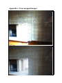
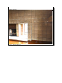
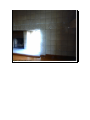
TNM078, Image Based Rendering Jonas Nilsson, Camilla Kemppainen LiU, Campus Norrköping 2007-02-17 HDR tone-mapping in real time - on NVIDIA 6800 light edition, 128 Mb memory. Abstract: As one of the examination step in the course Images Based Rendering, TNM078, a project about tone-mapping for HDR images in real time was implemented. Different operators were used such as S-curve, Rahman Retinex, Global Average, Logarithmic, Chiu's spatially variant operator. Also bloom effect was implemented. Best result gave the S-curve, which preserved details in both light and dark regions. Rahman Retinex was believed to give the best result since it is a local tone-mapping operator but did not preserve details in very bright regions. The shader language used was OpenGL shading language and the graphic card used was a NVIDIA 6800 light edition with 128 Mb memory. Index 1. Introduction......................................................................................................................3 1.1 Purpose...................................................................................................................... 3 1.2 Background............................................................................................................... 3 2. Shaders.............................................................................................................................4 3. Tone-mapping algorithms................................................................................................6 3.1 Global average.......................................................................................................... 6 3.2 S-Curve..................................................................................................................... 6 3.3 Logarithmic mapping................................................................................................ 7 3.4 Chiu's Spatially variant operator............................................................................... 7 3.5 Rahman Retinex........................................................................................................ 7 3.6 Bloom........................................................................................................................ 9 4. User manual................................................................................................................... 10 5. Results............................................................................................................................11 6. Discussion...................................................................................................................... 12 7. References......................................................................................................................13 Appendix 1. Tone-mapped images.................................................................................... 14 1. Introduction 1.1 Purpose In the course TNM078, Image Based Rendering, one of the examinations step consisted of making a project based on advanced, published work in the field of High Dynamic Range Imaging. The idea of HDR tone-mapping in real time was implemented with different kinds of tone-mapping operators. 1.2 Background In computer graphic the goal is to give each object in a scene certain properties. This could be done by giving an object in a scene a certain appearance by mapping a texture to the object. In this project High Dynamic Range, HDR, images was used as textures. HDR images are images with a lot of light information about the scene which gives a more accurate representation of the real world than Low Dynamic Range, LDR, images. The HDR textures were in angular format which made it appropriate to map them on a sphere. This enables the user to look around and see all direction when standing in the centre of the sphere. It could be called HDR panoramic viewer. At the moment LDR images are more commonly used but HDR images are gaining acceptance in the film industry, photography and computer graphics and soon all the LDR displays will be replaced with HDR displays. The process that maps textures to objects can be very computational heavy and to speed up this process this can be done for each pixel on the GPU, the graphic hardware, instead of using the CPU. Then the CPU will be free to handle other tasks or user commands and the application can render in real time, which is very important for example for video games. This is implemented by writing a so called shader and there are different shader languages that can be used. For this project OpenGL's shading language was utilized. Since all displays used at the moment are LDR displays the HDR images and textures has to be mapped in someway to make it possible to view them on the displays. In this project following tone-mapping methods were tested s-curve, global mean, logarithmic, Chiu's spatially variant operator and Rahman Retinex. The tone-mapping algorithms were executed in real time. Also a bloom effect was implemented to give the impression of that very bright areas are glowing. The program has been tested on NVIDIA 6800 light edition, 128 Mb memory. 2. Shaders A shader in the field of computer graphics is a set of software instruction, which is used by the graphic resources primarily to perform rendering effects. From a technical view a shader is a part of the renderer, which is responsible from calculating the color of an object1. The type of shader used in this project was pixel/fragment shader, which enables computations of colors, and texture coordinates per pixel. The inputs for the pixel shader are the interpolated values computed in the vertex shader such as vertex positions, colors, normals, etc. Therefore a vertex shader was needed as well. In the vertex shader these values are computed for each vertex. The pixel shader deals with the fragments inside the primitives, consequently the interpolated values are needed2. The original floating point HDR texture was generated from a RAW-file with float values or from the .hdr format by using code found in an NVIDIA demo3. In OpenGL the texture unit has to be specified to store floating point values, a feature only available on newer graphic cards. The format used was 16-bits per channel, and for this project the RGB channels was used. To be able to do tone-mapping on the rendered image a feature in OpenGL has to be used, which copies the rendered from the framebuffer to a texture. This texture is then mapped to a quad covering the whole screen. When rendering this quad a fragment shader was used to compute the tone-mapped image using different known image processing techniques. The framebuffer is the final step in the graphics pipeline. And most framebuffers uses an 8-bit format to store the RGBA values. Features in OpenGL was studied which enables the use of floating-point framebuffers. Since the features were not easily enabled and perhaps not possible to implement on the graphic card used. Was the RGBE-format used for rendering to the framebuffer. This approach only uses the 8-bit RGBA values available in the framebuffer, but needs a second fragment shader in the rendering process to transform the values between floating-points and RGBE. To be able to load the texture to the buffer in the graphic card a transformation from the floating-point format, the format of the textures when loaded into the program, to the RGBE-format had to be done. This transformation was done with the following equations: E =[log 2 max R w , G w , B w 128] R M =[ 1 256∗R w 2 E −128 ] Shader, [www], <http://en.wikipedia.org/wiki/Shader>, 14th of March 2007 GSL Tutorial, [www], <http://www.lighthouse3d.com/opengl/glsl/index.php?fragmentp> 14th of March 2007 3 Walter, Bruce, RGBE loading program, [www], <[email protected]> 16th of March 2007 2 G M =[ B M =[ 256∗G w 2 E−128 256∗B w 2 E−128 ] ] The parentheses for E ought to be roof-parentheses and for RM , GM , BM ought to be floor-parentheses. In the book High Dynamic range imaging, acquisition, display and image based lighting says that a base two should be used but it did not work in the reality, since it conveyed in artifacts in the picture. In the searching for solution to this problem did we found an old GDC presentation4 explaining that a higher value of the exponent leads to higher dynamic range but lower resolution (since there will be more dynamic range values per integer value) and Mach banding can become visible. Because of this was the exponent 2 in the above equations changed to 1.05. A value of 1.05 means a dynamic range of 1.05^256, enough range for our textures. To get back to the floatingpoint format, which was used in the tone-mapping, following equations was used: Rw = R M 0.5 E −128 ∗2 256 G w= B w= G M 0.5 E−128 ∗2 256 B M 0.5 E −128 ∗2 256 Here the base 1.05 was used again since it is necessary to use the same base in both transformations to keep it uniform as well as it worked better than with the base 2 as mentioned earlier. Three different fragment shaders were used in each rendering pass. The first is applied when rendering the scene, with the floating point texture mapped to the sphere. That shader calculates the RGBE value for each fragment, and returns those values as an RGBA color. These values are stored in the framebuffer and copied to a texture unit. A small quad is then rendered with the second shader. This shader applies a Gaussian filter on the texture and returns the RGBA values. The resulting framebuffer part covering the quad is copied to a new texture. By applying the second shader on larger quads, less blurred version of the image can be received. At last a big quad is rendered, covering the whole window, with the tone-mapping shader enabled. This shader takes the generated textures, calculates the floating point value from the textures RGBE value and applies the tone-mapping technique of choice. 4 (2004), Game developer conference, [www], <http://www.daionet.gr.jp/~masa/archives/GDC2004/GDC2004_PIoHDRR_SHORT_EN.ppt>, 16th of March 2007 3. Tone-mapping algorithms 3.1 Global average When the global average was used as a tone-mapping operator each pixel was simply divided by the global average. To decide the global mean the lowest mipmap-level, which is one pixel in size, was used and should be close to the global mean value for the texture. The computation was implemented for each colour channel. mean = tex_RGBE(envTexture, vec2(gl_TexCoord[0]),10)*exposure; color.r = color.r / mean.r; color.g = color.g / mean.g; color.b = color.b / mean.b; 3.2 S-Curve The response curve for rods and cones in the eye can be described with following equation: n R I = n R max I sigma n R is photoreceptor response in the interval 0 < R < Rmax. Rmax is the maximum response and I is the light intensity and sigma is the semisaturation constant, the intensity that causes the half-maximum response. And finally n is a sensitivity exponent that has a value generally between 0.7 and 1.0. On a log-linear plot this equation is shaped as an S5. Sigma controls the position of the S-curve on the horizontal axis. This curve was used to tone-mapp the HDR images. The tone-mapping procedure was done on each colour channel and the value for sigma was decided from the lowest level of the mipmap which is one pixel in size and ought to be close to the global average for the image. color.r = color.r / (color.r + mean.r); color.g = color.g / (color.g + mean.g); color.b = color.b / (color.b + mean.b); 5 Reinhard, Erik, et al, (2006), High Dynamic Range Imaging acquisation, Display and image-based lighting, page 198. 3.3 Logarithmic mapping The simplest non-linear mapping is to do a logarithmic mapping. In this project following equation was used to do a logarithmic mapping6: L d x , y = lo g 10 1L w x , y lo g 10 1 L max x , y Lmax is simple the highest value in each colour channel since this operator also was coded channel wise. 3.4 Chiu's Spatially variant operator Chiu et al noticed that artists often make use of spatially varying techniques to fool the eye into thinking that a much larger dynamic range is present in artwork then actually exists. In particularly, the areas around bright features may be dimmed to accentuate them. The Chiu operator simply multiplies the image with a local scale factor meaning that it depends on the pixel value it self and a surrounding neighbourhood. To make the scale factor represent a local average a low-pass filtered image of the original is produced. In a blurred image each pixel represents a weighted local average of the pixel in the corresponding position of the original. To compress the image following equation was implemented7: L d x , y = 1 k∗L blur w x , y ∗L w x , y The blur was created with a Gaussian filter kernel. 3.5 Rahman Retinex Rahman Retinex is a local tone-mapping operator, which means that it computes a local adaptation level for a pixel based on its pixel value itself as well as a neighbourhood surrounding the pixel of interest. The neighbourhood decides how a pixel is compressed therefore a very bright pixel in a dark neighbourhood is treated differently than a very bright pixel in a bright neighbourhood8. To create this local neighbourhood of adaptation a Gaussian filter is used and convolved with the image. Since the operator works independently on each colour channel, r,g, and b the convolution is done three times9. There are two different versions of Rahman Retinex, a single-scale and a multiscale6 Reinhard, Erik, et al, (2006), High Dynamic Range Imaging acquisation, Display and image-based lighting, Page 252 7 Reinhard, Erik, et al, (2006), High Dynamic Range Imaging acquisation, Display and image-based lighting, Page 278. 8 Reinhard, Erik, et al, (2006), High Dynamic Range Imaging acquisation, Display and image-based lighting, Page 223 9 Reinhard, Erik, et al, (2006), High Dynamic Range Imaging acquisation, Display and image-based lighting, Page 282 version. In the multi-scale version the equation for single-scale is repeated several times for Gaussians filters with different kernel sizes. The multiscale retinex version is then simple the weighted sum of a set of single-scale retinex images.10. w n= N −n 1 f N ∑ N −m1 f n=0 N I d x , y =e bl ur w n ∗logI w x , y −k∗logI w , n x , y ∑ n=0 The parameters f and k are user parameters and f adjusts the relative weighting for the image divided with each blurred image. The equation says original minus the blurred image but the operation is done in the logarithmic domain which represents a division. The value of k specifies the relative weight of the blurred image. The multiscale version was implemented in this project. But instead of doing filtering with different sizes of Gaussian filter kernels the original image was downscaled to six different sizes and these were then filtered with the same Gaussian filter kernel. const float gauss[5] = {1.0/273.0,4.0/273.0,7.0/273.0,26.0/273.0,41.0/273.0}; outcolor = color / (k*tex_RGBE(blur1, vec2(gl_TexCoord[0]),0)); To use the existing mipmaps in the graphic card as different scales of the texture was tried out but it caused artifacts, shaped like stars, so instead different scales of the texture was sent to the shader. Examples on the internet described this way to do the filtering rather than to use the mipmaps11. Still the filtering method is not perfect since the image appear to be “blockish” which is hard to understand why. After all OpenGL does a linear interpolation when down-scaling the texture. 10 Reinhard, Erik, et al, (2006), High Dynamic Range Imaging acquisation, Display and image-based lighting, Page 282. 11 How to do good bloom for HDR rendering, [www], <http://harkal.sylphis3d.com/2006/05/20/how-to-dogood-bloom-for-hdr-rendering/>, 16th of March 2007. 3.6 Bloom To create the effect that very bright areas seem to be glowing, a bloom effect was implemented. This was done in the same way as the Gaussian blur in the Rahman Retinex tone-mapping operator. Different scales of the texture was filtered with a Gaussian filter kernel and then weighted and combined together with the original to get the bloom effect. An image with bloom effect still needs to be tone-mapped to be adjusted to the display’s lower dynamic range. At the moment one large filter kernel is being used but if the program runs too slowly the filter kernel could be separated to two one dimensions filter kernel. Then the filtering would be done in horizontal and vertical direction. The bloom effect should only appear in very bright areas otherwise it gives the image a very dreamy appearance, which could be good if that is what, is asked for. Since the blooming operator is not a complete tone-mapping algorithm, both the blurred and the original image needed to be tone-mapped before display and this was done with the S-curve. 4. User manual The requirements for the system are a GLSL enabled graphic card, which can handle 16bit floating-points textures. Furthermore the textures must be located in a correct folder. It is possible to change the exposure on the texture by clicking the + and – buttons on the keyboard. The mouse can be used to navigate in the sphere. To rotate the left button should be pressed and the mouse moved. To zoom the middle button is pressed and the mouse dragged. When the right mouse button is pressed a menu will be displayed where items can be selected by pressing the left button. Following items will appear in the menu list: Autorotation causes the sphere to automatically rotate, nice for displaying the program. Texture menu where the texture for display can be chosen. Tone-mapping menu where tone-mapping operator can be chosen. Reload the shader file, if changes was made in the shader file. 5. Results When using the global average operator it can not preserve the dynamic range. Details are lost in very bright areas (see appendix 1, figure 1). The S-curve operator represent bright areas very well and very dark areas are rather good (see appendix 1, figure 2). Rahman Retinex was the method which was believed to be the best one due to the fact that it is a local tone-mapping operator and the others are global tone-mapping operator. It failed in very bright areas where details were lost but gave the best result in very dark areas of all the operators implemented in this project. Rahman Retinex is probably very good in still images where the local neighbourhood is fixed. Somehow artefacts in the shape of blue splashes appeared in very dark regions. Chiu spatially variant operator almost gave the same results as Rahman, but with a more noticeable haloing effect around edges. The logarithmic tone-mapping gave almost the same effect as the S-curve but reduced the framerate to 10 frames per second while running the s-curve the framerate was between 10-70 frames per second depending on the texture. 6. Discussion From what can be seen from the results the s-curve is the best tone-mapping operator implemented in this project. It can preserve details in both dark and bright areas and at the same time it runs rather fast and smooth. The blooming effect can also be implemented, with caution, as it looks nice and is fast to compute (See Appendix 1, figure 4). There are a lot of problems related to the internal functions of the graphic card and the OpenGL method used. The strange blue artefacts in the Rahman Retinex implementation and the artefacts appearing when using an exponent 2 in the RGBE calculations can be effects caused by some part of the graphic pipeline that the group members did not have control over. Most functions of the graphic card have corresponding OpenGL methods, but since most of these are OpenGL extensions, the documentations is hard to find and difficult to understand. Newer graphic hardware and software will support floating-point framebuffers and HDR textures without problems and should make tone-mapping more flexible. 7. References • • • • • • Reinhard, Erik, et al, (2006), High Dynamic Range Imaging acquisation, Display and image-based lighting. How to do good bloom for HDR rendering, [www], <http://harkal.sylphis3d.com/2006/05/20/how-to-do-good-bloom-for-hdrrendering/>, 16th of March 2007. (2004), Game developer conference, [www], <http://www.daionet.gr.jp/~masa/archives/GDC2004/GDC2004_PIoHDRR_SHO RT_EN.ppt>, 16th of March 2007. Walter, Bruce, RGBE loading program, [www], <[email protected]> 16th of March 2007. GSL Tutorial, [www], <http://www.lighthouse3d.com/opengl/glsl/index.php?fragmentp> 14th of March 2007. Shader, [www], <http://en.wikipedia.org/wiki/Shader>, 14th of March 2007. Appendix 1. Tone-mapped images Figure1: Mean Figure 2: S-curve Figure 3: Rahman Retinex Figure 4: Bloom and S-curve