1
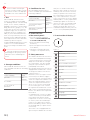
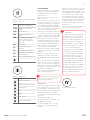
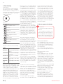
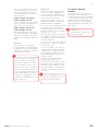
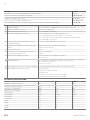
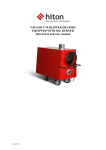
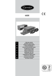
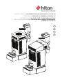
INSTRUKCJA OBSŁUGI NAGRZEWNICY NA OLEJ UNIWESALNY HP-115 I HP-125
USER MANUAL UNIVERSAL OIL HEATER HP-115 AND HP-125
LUFTERHITZER FÜR MB-ÖL HP-115/HP-125 BEDIENUNSANLEITUNG
ИНСТРУКЦИЯ ЭКСПЛУАТАЦИИ НАГРЕВАТЕЛЯ НА УНИВЕРСАЛЬНОМ МАСЛЕ
МОДЕЛИ HP-115 И HP-125
PL
H P - 11 5
ENG
DE
RU
H P -12 5
HITON - heat your home, not the planet
|1
PL
Spis treści:
ENG
Table of contents:
Rysunki techniczne
3
Figures and drawings
3
1. Przeznaczenie
6
1. Use
12
2. Warunki środowiskowe składowania
6
2.Storage conditions
12
3. Warunki środowiskowe użytkowania
6
3. Conditions for use
12
4. Cechy charakterystyczne sterownika
6
4. Characteristics of the control panel
12
5. Aspekty bezpieczeństwa
6
5. Safety measures
12
6. Konstrukcja urządzenia
6
6. Construction of the heater
12
7. Instalacja urządzenia
7
7. Installation
13
8. Opis działania urządzenia
8
8. Functionning
14
9. Obsługa nagrzewnic
8
9. How to operate the heater
14
10. Naprawa usterek
9
10. Failures and remedies
15
DANE TECHNICZNE
10
TECHNICAL SPECIFICATIONS
16
DEKLARACJA ZGODNOŚCI WE
11
EC DECLARATION OF CONFORMITY
17
DE
Inhaltsverzeichnis:
RU
СОДЕРЖАНИЕ:
Technischen Zeichnungen
3
Технические рисунки
3
1. Bestimmung
18
1. Предназначение
24
2. Umgebungsbedingungen der Lagerung
18
2. Условия складского хранения
24
3. Umgebungsbedingungen der Nutzung
18
3. Эксплуатационные условия
24
4. Eigenschaften des Steuerers
18
4. Характеристика контроллера
24
5. Sicherheitsaspekte
18
5. Безопасность
24
6. Einrichtungskonstruktion
18
6. Конструкция устройства
25
7. Einrichtungsinstallation
19
7. Установка устройства
25
8. Beschreibung der Einrichtungswirkung
20
8. Описание работы устройства
26
9. Bedienung des Lufterhitzers
20
9. Обслуживание нагревателя
27
10. Fehlerbehebung
21
10. Устранение неисправностей
28
TECHNISCHEN DATEN
22
ТЕХНИЧЕСКИЕ ДАННЫЕ
29
EG-KONFORMITÄTSERKLÄRUNG
23
ДЕКЛАРАЦИЯ СООТВЕТСТВИЯ
30
2|
www.hiton.pl
HITON - heat your home, not the planet
|3
T40
T100
MP
MW
OVF
D1
D2
KB
D3
D4
6
5
4
3
2
1
M
4
3
2
1
M
JP-1
JP-2
3
2
1
JP-3
4|
www.hiton.pl
min. 500 cm
Ø 150
START
START
HITON - heat your home, not the planet
STOP
|5
ENG
Please read the following instruction carefully in order to make
sure that the heater is used properly and does not cause malfunction.
1. Use
HP-115 and HP-125 universal oil
heater are suitable for heating big
size buildings without central heating
(shops, service stations, industrial
buildings, warehouses, inventory buildings, basements, garages, etc.) The
heater runs on most oils of mineral
and plant origin, such as motor oils,
heating oil, gear oils, hydraulic oils,
HBO I, II, III oils with maximum kinematic viscosity 6.00 mm²/s at a temperature of 20ºC and maximum ignition temperature not lower than40ºC
and density above 0.94 g/cm³.
In light of binding regulations in some
countries it is recommended that
diesel oil, heating oil or biodiesel be
used.
Not to be used with transformer
(insulating) oils. They may contain
substances that can damage the
heater
2. Storage conditions:
HP-115 and HP-125 universal oil heaters should be stored in the following
conditions:
temperature
-20-85°C
relative humidity
5-85%
pressure
8001200hPa
V
free of dust
free of chemical
pollutants
V
3. Conditions for use:
WDQNWKHVRFDOOHGRYHUǻRZIXVH
HP-115 and HP-125 universal oil
heaters should be operated under the
following conditions:
When the tank is filled, the heater imPHGLDWHO\VZLWFKHVLQWRWKHRYHUǻRZ
mode (see point 8 of the instruction).
temperature
0-30°C
relative humidity
5-85%
pressure
8001200hPa
environmental impact
protection
IP20
appropriate ventilation
of heated area
V
4. Characteristics
of the control panel:
The control panel of the heater is factory-connected with other elements
of the system (such as sensors, pump,
and fan) and it is a safety requirement
that during regular use there be no
interference with covered and sealed
part of the control panel as well as
integrity of wiring. Any interference
of unauthorized person may cause an
electric shock (230V/50Hz) and burns.
6. Construction of theater
ǗWKHKHDWHUPD\EHUHJXODWHG
and set at 15 and 22kW (HP-115)
or 22 and 30 kW (HP-125),
ǗSURWHFWLRQDJDLQVWRYHUKHDWLQJ
the burner,
ǗSURWHFWLRQDJDLQVWRYHUǻRZRIRLO
in the burner,
ǗDXWRPDWLFUHWDLQLQJRISUHYLRXV
settings in case of power failure,
5. Safety measures:
HP-115/HP-125 universal oil heater is
connected to 230V/50Hz alternating
current network. A fuse element (1A,
250V) was installed in the casing of
the control panel. The fuse should
always be replaced with the power
(230V/50Hz) switched off.
HP-115 /HP-125 universal oil heater is
equipped with two bimetallic sensors
assuring safe and effective functioning of the device.
Bimetallic sensor (see figure 4 of the
instruction) in the burner triggers
reaction in form of clenching contacts
when the temperature in burner rises
above 40°C and opening of contacts
when the temperature falls below
35°C. In cases such as overheating
RURLORYHUǻRZSURFHVVRUFRQWUROV
the signal from the bimetallic sensor
and activates ventilating fan until the
burner cools down to the temperature
below 35°C.
Second bimetallic sensor (see figure
1 of the instruction) is installed next
to the blower fan with threshold
temperature set at 90°C. Clenching
of contacts, when threshold temperature is exceeded, causes that the
burner immediately switches into the
overheating mode (see point. 8 of the
instruction).
Figure 1:
Terms:
Overheating control
Burner lid
Oil feed line
Burner chamber thermostat
Pump and control panel
Fuel tank
Cylinder
Ring
Wire ring
Combustion chamber
Vaporising pan
Combustion chamber basin
ǻRZJDXJH
RYHUǻRZIXVH
The heater is also equipped with weLJKVHQVRUSODFHGXQGHUWKHRYHUǻRZ
12 |
www.hiton.eu
ENG
7. Installation
When installing the heater, all local
regulations are to be complied with,
including regulations referring to
national norms.
1. 3ODFHWKHKHDWHURQǻDWVXUIDFH
made of concrete.
Figure 2: Diagram of HP-115 and HP-125
universal oil heater
T40
Bimetallic sensor
of burner’s temperature
T100
Bimetallic thermostat
(STB)
OVF
MP
2YHUǻRZIXVH
MW
Fan (35W [230V/50Hz],
capacity 600 m³/h (HP115), capacity l000 m³/h
(HP-125)
KB
D1
Keyboard
Pump (48W [230V AC,
50Hz])
Heater overheating
indicator
D2
D3
2YHUǻRZWDQNLQGLFDWRU
D4
Heater turn on/off indicator
Pump engine rotational
speed indicator
2. Level the device in order to check if
the heater is levelled correctly, place
the vaporising pan in the lower part of
the combustion chamber and pour a
small amount (approximately 250ml)
of diesel oil onto it. The oil should stay
exactly in the middle of the pan.
3. Install current stabilizer (valve) on
the combustion chamber’s outlet pipe
in order to maintain constant draught
inside the pipe during the operation.
4. Install at least six meters long,
smooth and temperature resistant
KRUL]RQWDOǻXHQRWDOXPLQLXPǻXHLQ
order to provide optimum draught.
5. Check tightness of all joints, if necessary use the insulation tape.
6. Make sure that the vaporising pan
is placed centrally in the combustion
chamber.
7. Place the upper ring inside the
FRPEXVWLRQFKDPEHUZLWKǻDQJH
facing upwards and install the hot air
pipe.
8. Check the power (220-240V/50Hz)
and connect the heater to the power
outlet. Neither fan nor the pump should become active because the burner
has not been switched on and the heat
has not been produced yet.
9. The heater should be placed away
from combustible materials
Figure 3: Control panel
Terms:
burner thermostat
STB bimetallic thermostat
RYHUǻRZIXVH
fan
pump
230V, 50 Hz
control panel HP-125
,ISRVVLEOHDOOVHFWLRQVRIWKHǻXHVKRuld be in vertical position, horizontal
positioning should be avoided, as well
DVEHQGLQJRIWKHǻXH+RZHYHULILWLV
QHFHVVDU\WREHQGDǻXHIRUH[DPSOHDǻXHEHQWLQWZRSODFHVZKHQLW
runs through a wall or a window), the
maximum angle is 45° with minimum
KHLJKWRIWKHǻXHLQFUHDVHGWRP
0LQLPXPǻXHGUDXJKWRI3DZLWK
nominal heat.
The device cannot be connected to the
joint combustion outlet system.
CAUTION!
When installing the combustion
outlet system it is recommended
QRWWRSODFHǻXHVLQKRUL]RQWDO
position. In order to guarantee free
movement of gases, the angle of
ǻXHVKRXOGQRWH[FHHGr7KHǻXH
outlet must be above the rooftop.
Flues running through the
ceiling, walls or the roof, must be
insulated in order to prevent fire.
It is recommended to use double
VNLQQHGǻXHLQSODFHVZKHUHWKH
ǻXHLVOLNHO\WREHWRXFKHGE\WKH
general public and on the outside of
the building in order to guarantee
good draught and prevent condensation. No materials should be
placed close to the heater, even
incombustible ones. Free air movement should be provided to assure
proper combustion process.
Ventilation fans working in the
same room or area as the heater
may cause disruptions.
Fitting the flue
To ensure the right combustion approSULDWHǺWWLQJRIWKHǻXHLQQHFHVVDU\ Figure 4: Fitting the flue
The following recommendations shoXOGEHDGKHUHGWRZKHQǺWWLQJWKHǻXH
0LQLPXPǻXHGLDPHWHUPP
&KHFNWLJKWQHVVRIMRLQWVEHWZHHQǻXH
elements.
0LQLPXPǻXHKHLJKWP
7KHLQVLGHRIWKHǻXHVKRXOGEHLQVXlated (double skinned).
The tube should be in free air (the
WLSRIWKHǻXHVKRXOGEHDERYHWKH
rooftop).
HITON - heat your home, not the planet
| 13
ENG
8. Functionning
blower fan; these are signalled by the
yellow diode on the control panel. At
the beginning smaller amount of oil
The control panel of HP-115and HPis required for at least 30 minutes,
125 universal oil heater is equipped
when the burner has not been heated
with four buttons enabling the user to up, and the device should work on its
control the operation of the heater and first gear (on the screen displayed as
four diodes signalling the operating
“-“ – yellow diode is dim). During this
modes of the device.
time, the pump feeds the combustion
chamber with approximately 1.25
kg/h (HP-115) or 1.85 kg/h (HP-125) of
oil. After 30 minutes, we may shift to
second gear (on the screen displayed
as “+” – yellow diode is bright), during
which time the chamber is supplied
with approximately 1.85 kg/h (H-P115)
Figure 5: ..
or 2.55 kg/h (HP-125) of oil.
Terms:
The heater is switched off by presheater output control
sing Stop button on the control panel.
The pump is switched off (yellow and
on switch
green diodes on the control panel go
off). Ventilation fan works until the
off switch
temperature in the chamber falls
below 35°C (Shutting off). After the
temperature in the chamber has faloverheat control STB
len below 35°C, the burner switches
to the Stop mode.
9DSRULVLQJSDQRYHUǻRZ
control
Control panel
pump control
heater readiness for use
LED diodes
The device operates in the following
modes:
STOP
Device ready for use
HEATING UP
Preliminary operating
phase
IN OPERATION
SHUTTING OFF
The device is working
normally
The device is shutting
off
OVERHEATING
Contingency switching
off
TANK OVER-
Contingency switching
off
FLOW
The heat is produced during gas combustion when oil is heated up to a high
temperature. When connecting the
heater to power network, the device
is in stand-by mode (Stop). Heat is not
produced and fan and pump are not
working. Pressing the Start button
triggers the green diode to turn on
and the heater goes into the heating
up mode. Once the burner is heated
up to 40°C the joints of thermostat
placed next to combustion chamber
clutch activating the oil inlet pipe and
14 |
The heater may switch off automatically if the combustion chamber is
RYHUKHDWHGRULQFDVHRIRYHUǻRZ
Overheating signal is generated by the
bimetallic thermostat located close
to the fan. Opening of joints signals
that the threshold temperature has
been exceeded. Control system turns
the pump off (pump indicator, yellow
diode, goes off) and overheating is
signalled when a red diode on the
control panel switches on. Ventilation
fan works until the temperature in the
chamber falls below 35°C. After the
temperature in the chamber has fallen below 35°C, the burner switches
to the Stop mode
Once the heater is in the Stop mode
(and even after switching off and subsequently switching on the device) the
overheating signal is on. This enables
the user to find out what caused the
heater to stop.
In order to reset the overheating
signal and regain normal functioning
of the device, one should wait until the
burner cools off completely (ventilation fan switches off) and press the
button on the casing of bimetallic
thermostat. Then press Start button,
which will cause the overheating
diode to go off. The heater may be
switched on again.
2YHUǻRZVLJQDOLVJHQHUDWHGE\D
mechanic sensor located underneath
WKHRYHUǻRZWDQN2SHQLQJRIMRLQWV
VLJQDOVWKDWWKHWDQNLVRYHUǻRZ$W
the same time the pump is switched
off, the pump indicator goes off, and
WKHUHGGLRGHVLJQDOOLQJRYHUǻRZVZLWches on. Ventilation fan works until
the temperature in the chamber falls
below 35°C. After the temperature in
the chamber has fallen below 35°C,
the burner switches to the Stop mode.
7KHRYHUǻRZWDQNLVWREHHPSWLHG
and then Start button should be presVHGZKLFKZLOOFDXVHWKHUHGRYHUǻRZ
diode to go off. The heater may be
switched on again.
9. How to operate the heater
CAUTION!
Oil must not be poured into the
burner if
The chamber or the pan is still
hot!!! Always wait until the burner
has cooled down. Non-compliance
with the above warning may cause
explosion of oil vapours and burns!!!
How to operate the device
Once engaged, the heater switches to
desired modes depending on settings
chosen by the user and information
transmitted by sensors connected to
the control panel.
If necessary, water may be poured
from the tank and replaced with used
oil.
Plug into the power socket
(230V/50Hz).
Pull the upper part of the cover aside
and take the burner lid off, take the
cylinder and the ring out (if necessary,
clean thoroughly the vaporising pan
and its base, the burner, cylinder and
ring). Check if the vaporising pan is
cool and clean, and then pour approximately 250 ml of heating or diesel oil
onto it.
Light oil using a piece of scrunched up
paper that needs to be put on fire and
thrown onto the vaporising pan.
Install ring and cylinder, put the burner lid back on, close the upper part
of burner’s casing.
Press Start button on the control
panel (green diode turns on)
After approx. 10-15 minutes, depending on the temperature in the room,
the fuel pump and ventilation fan will
start and the yellow pump diode will
www.hiton.eu
ENG
turn on at the same time. The heater
starts working on the lowest gear
with lower performance and can
continue operating in this mode on a
continuous basis:
15 kW; 1.25 kg/h – HP-115 and
22 kW; 1.85 kg/h – HP-125
The second gear, with increased performance can be activated by selecting “+” on the control panel:
22kW; 1.85 kg/h – HP-115 and
30 kW; 2.55 kg/h – HP-125
Each time Stop button is pressed
followed by pressing the Start button
during operation will result in switching into the Heating up mode of the
burner.
Shutting off
Press Stop on the control panel
(yellow diode goes off), pump stops
feeding fuel onto the vaporising pan,
and ventilation fan works only until
the burner has cooled off.
The device must not be unplugged for as long as the ventilation
fan is working, this can be done
only after the burner has cooled
down. The burner switches off
automatically. Please remember
that after switching off the device,
the cast-iron pan remains hotter for
longer (depending on the temperature in the room) and the heater
cannot be re-engaged until it cools
down completely.
HITON - heat your home, not the planet
Maintenance
The burner requires various maintenance works. Following producer’s
recommendations regarding maintenance will assure failure-free and
safe functioning of the device.
Vaporising pan and elements of the
combustion chamber (cylinder, ring
and lid) should be cleaned daily.
&KHFNLIWKHRLORYHUǻRZSLSHLVXQREstructed (this pipe is located in the
lower part of the combustion chamEHUGLUHFWO\DERYHWKHRYHUǻRZWDQN
and clean if necessary.
Clean the burner basin located inside
the combustion chamber at least once
a week (burner basin is located under
the vaporising pan).
10. Failures and their
remedies
In case of a failure of the device, the
following list may help identify its cause and remedy. Generally, it should be
easy to fix. The following are the most
common problems. Digits represent
possible causes. The order of digits
suggests gradation of probable cause
of the failure.
CAUTION!
Unplug the device before starting to fix the problem.
Check if air inlets in the lower and upper part of the combustion chamber
are not obstructed.
Clean the oil feed line once a week,
maximum time of operation without
cleaning the line feeding oil onto the
vaporising pan is approximately 7-14
hours (depending on the type of oil
used for heating).
Clean the fuel tank and oil pump
filters during heating season.
If the heater is not used for a longer
period of time, the combustion chamber and the tank should be cleaned
thoroughly, and then covered with a
thin layer of oil in order to prevent
corrosion.
It is recommended to have all
maintenance works done each seazon by an authorised dealer
| 15
ENG
FAILURE
CAUSE
Pump does not work and the pump indicator does not turn on
6-3-7
Flame goes off while the pump is still working
2 - 5 - 9 - 10 - 12
Combustion chamber makes noise
10 - 11 - 12
7KHUHLVVRRWLQWKHFKDPEHUDQGRQWKHǻXH
8 - 9 - 10 - 11 - 12
There is unburned oil left on the vaporising pan or too much diesel oil during switching on
8 - 9 - 11 - 12
CAUSE
REMEDY
1
No power supply
Check if the device is plugged in correctly and check the fuse.
2
Water or residues in the tank.
Clean the tank and filter
3
Pump engine does not turn on
&KHFN67%DQGRYHUǻRZIXVH
4
The engine and pump do not turn on.
No
Fuel is too thick or too cold. Dilute with diesel oil.
Check the pump thermostat and replace, if necessary.
Check the engine in order to determine if the pump is not dirty inside.
&KHFN67%DQGRYHUǻRZIXVH
5
2LOSLSHLVEORFNHGRLOǻRZVEDFNWRWKHWDQN
through return pipe
Clean the oil pipe and replace, if necessary.
6
Pump thermostat did not reach desired temperature.
Wait until the burner cools down and relight.
7
2YHUǻRZIXVHLVIXOO
Clean
8
Security thermostat (STB) does not work correctly or does not work at all
Reset the thermostat
9
Insufficient air supply for heating
Clean air inlets in the combustion chamber.
Replace the thermostat.
Replace
Check the fan
10
Draught problems
&KHFNLIWKHǻXHLVLQVWDOOHGDFFRUGLQJWRǒ)LWWLQJWKHǻXHǓ
&KHFNWLJKWQHVVRIWKHǻXH
Clean, if necessary
11
7KHGUDXJKWLQWKHǻXHLVWRRVWURQJRUFKDQJLQJ
Install the draught stabiliser and set at 2 mm W.C. (16 Pa).
12
7KHGUDXJKWLQWKHǻXHLVWRRZHDN
Check all joints.
Minimize the number of bends
([WHQGWKHǻXH
,QVXODWHWKHǻXHRQWKHRXWVLGHRIWKHEXLOGLQJ
5HDGLQIRUPDWLRQDERXWWKHǻXHLQWKLVJXLGH
TECHNICAL SPECIFICATIONS:
HP115
HP125
Minimum heating performance
kW
15
22
Maximum heating performance
kW
22
30
Minimum oil consumption
kg/h
1,25
1,85
Maximum oil consumption
kg/h
1,85
2,55
+HDWHGDLUǻRZ
m3
600
1000
Power supply
V/Hz
230/50
230/50
Power intake
A
0,6
0,6
Flue diameter
mm
150
150
Width
cm
54
85
Height
cm
137
137
Length
cm
75
54
Weight
kg
90
90
16 |
www.hiton.eu
ENG
ABIZA
ABIZA
Poland, 05-825 Grodzisk Mazowiecki
Poland, 05-825 Grodzisk Mazowiecki
Opypy, ul.Jemiołowa 2
Opypy, ul.Jemiołowa 2
08
EN 1
Type: HP 115
Distance from combustible materials: 140 cm
Class: 5
Heating performance: 22 kW
Fuel type: Diesel oil
Electric security: complied with
08
EN 1
Type: HP 125
Distance from combustible materials: 140 cm
Class: 5
Heating performance: 30 kW
Fuel type: Diesel oil
Electric security: complied with
EC D EC L A R AT IO N O F C O NFO R MI T Y
EC D EC L A R AT IO N O F C O NFO R MI T Y
Manufacturer:
ABIZA
Manufacturer:
ABIZA
Address:
05-825 Grodzisk Mazowiecki
Opypy, ul.Jemiołowa 2, Poland
Address:
05-825 Grodzisk Mazowiecki
Opypy, ul.Jemiołowa 2, Poland
Product:
Marka: HP
Product:
Marka: HP
Model: HP-115
Model: HP-115
We herby declare In sole responsibility that the designated product fulfills the safety requirements of the European Directives.
We herby declare In sole responsibility that the designated product fulfills the safety requirements of the European Directives.
Directives:
Directives:
2006/95/WE
Dyrektywą niskonapięciową (LVD)
2006/95/WE
Dyrektywą niskonapięciową (LVD)
2004/108/WE
Dyrektywą Kompatybilności
Elektromagnetycznej (EMC)
2004/108/WE
Dyrektywą Kompatybilności
Elektromagnetycznej (EMC)
89/106/WE
Dyrektywą Wyroby Budowlane
89/106/WE
Dyrektywą Wyroby Budowlane
Standards applied:
Standards applied:
PN-EN 1, PN-EN 1:2001/A1, PN-EN 60335-1, PNEN 60335-1-102, PN-EN 55014-1:2007, PN-EN
55014-2:1999+A1:2004+IS1:2007, PN-EN 550141:2004, PN-EN 61000-3-2004+ A2:2005, PN-EN
61000-3-3:1997+A1:2005+A2:2006, PN-EN 55014-1,
PN-EN 61000-4-2: 1999+A2:2003, PN-EN 61000-4-4:2005,
PN-EN 61000-4-6:2007, PN-EN 61000-4-5:2006, PN-EN
61000-4-11:2007, PN-EN 61000-3-3:1997+A1:2002(U)
CE marking was made in: 2008 r.
CE marking was made in: 2008 r.
Declaration issued by: ABIZA
Declaration issued by: ABIZA
Place, date: Opypy, 12.08.2008
Place, date: Opypy, 12.08.2008
Andrzej Białous
właściciel firmy
Andrzej Białous
właściciel firmy
Signature of authorized person
Signature of authorized person
HITON - heat your home, not the planet
| 17