1
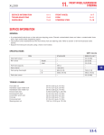
SFD
Suburban Filter Dryer
User Manual
Installation Instructions
Take your air system into the future with patented,
molecular sieve technology used in the SFD
regenerative cycle compressed air drying system.
764-2008 03
YOUR SAFETY IS IMPORTANT
Read ALL instructions before you begin the installation of your SFD
Observe and follow all caution and warning instructions
!!CAUTION!!
**SYSTEM PRESSURE MUST BE RELEASED
PRIOR TO INSTALLING DRYER**
• SFD dryer should be installed with a bypass circuit to provide
proper maintenance to unit
• Always wear eye protection when working on SFD dryer
• Use only proper tools and follow all precautions which pertain to
the use of those tools
• Use appropriate thread sealant on all fittings unless otherwise
specified
IMPORTANT! Installation of the all the moisture and oil removing
peripherals should be done before mounting SFD to the wall.
**It is recommended to install dryer with a bypass circuit for maintenance purposes**
— use appropriate thread sealant on all fittings unless otherwise specified —
TABLE OF CONTENTS
Safety Precautions …... …………………Page 2
Table of Contents ……. …………………Page 3
Technical Description .. …………………Page 4
Installation Instructions …………………Page 5-8
Dryer Accessories …... …………………Page 9
Maintenance Guide …. …………………Page 10-11
Warranty …………….. …………………Page 12
Congratulations on your purchase of the Tsunami™
Suburban Filter Dryer (SFD). We are very pleased
that you have decided to use the latest technology
to improve your compressed air system.
Your air system, using patented drying technology
will provide years of service with little
maintenance required.
Thank You.
The Tsunami™ Suburban Filter Dryer
Product Description
The Tsunami™ Suburban Filter Dryer uses the latest technology to provide your shop with the
cleanest, driest compressed air available.
Provides a consistent –10° F dew point with only a 4% sweep rate. Sweep rate refers to the
amount of the clean, dry air which is used to “sweep” through the molecular sieve canister
carrying along the water vapor that is captured by the molecular sieve desiccant bead.
This technology accomplishes its goal by taking the inlet air through one of the desiccant
canisters which removes the water vapor contained in your compressed air. The molecular
sieve bead draws the vapor in while under system pressure, holding it until the cycling of the
dryer allows the pressure to be
released in the canister, thereby allowing the water vapor to be removed with the sweep air.
This technology uses two canisters, while one is under pressure the other canister is in its
sweep cycle.
Each canister contains over six
pounds of molecular sieve desiccant.
These are the inlet check valves which shift
the cycling of the canisters.
The two unloading purge valves are in the
SFD body behind the inlet check valves.
This timer and cord set has a built in timer with a two
minute cycle time. When the timer opens the solenoid,
the connected three-way valve shifts, changing the cycling of the canisters.
This schematic shows a colored representation of the
air flow path through the SFD unit.
•
The red indicates the hot, wet air coming into the
dryer.
•
The blue shows the removal of the water vapor from
the air and is now very dry, clean air.
•
The tan color depicts the water vapor and its removal
during the regeneration cycle of the SFD dryer.
INSTALLATION INSTRUCTIONS
**SYSTEM PRESSURE MUST BE RELEASED
PRIOR TO INSTALLING DRYER**
**It is strongly recommended to install a bypass circuit around the dryer**
Open inlet and outlet ball valves
and close the bypass valve to use
dryer in the air system
Close inlet and outlet ball valves
and open the bypass valve to
bypass the dryer
NOTE: For optimal system efficiency, close inlet and outlet ball valves when air system is idle
—At the end of the day and over the weekend or anytime compressed air is not being used—
Step 1
Step 1a
Mount dryer wall bracket on
wall with appropriate hardware.
Step 2
Step 1b
Place dryer mounting bracket
into wall bracket slot.
Remove the plugs from the left and right front ports of the dryer
using a 1/4” hex wrench.
Step 3
Place thread sealant on the 1/4” nipple and mount the automatic
drains for the water separator and oil coalescing pre-filters.
Note:
This port is to be routed to
the strainer on the water
separator and oil coalescing
pre-filters.
Please note that the
intermittent air end is
attached to dryer
with nipple
Note:
This is the drain discharge port.
Route tubing to floor drain or bucket
Step 4
Use appropriate thread sealant at all connections
Step 4a
Step 4b
Assemble the bushing, elbow
and barbed nipple before
attaching to filtration package
Step 5
Step 4c
Securely mount the mounting
bracket using proper mounting
bolts
Assemble the nipple, elbow and
barbed fitting then install on the
inlet port of the SFD Dryer
Attach pre-filter package to
the mounting bracket using
supplied mounting bolts
Note mounting location
Assemble the nipple and union
then install on the outlet port of
the SFD Dryer
Step 6
Slide the flexible hose over the
barbed nipples and tighten hose
clamps securely
Step 7
Connect the drain lines from the
Moisture Minder® piston drains to the side
of the strainer at the bottom of the water
separator and oil coalescing filter using the
supplied 1/4” black tubing
Note: Make sure ball valve on strainer is closed
Step 8
Install mufflers as shown.
Do not over-tighten, hand tight is OK
!! Important !!
Use anti-seizing compound when
installing mufflers as shown
Step 9
If towers are not pre-assembled, lubricate the o-ring on the can mounts as well as the
ring on the canister using supplied lubricant. Apply a small amount to the threads.
!! IMPORTANT !!
DO NOT OVER TIGHTEN THE CANISTERS.
ONCE THE RING MAKES CONTACT WITH THE BASE, TIGHTEN 1/8 TO 1/4 TURN MAX.
Step 10
If labels are not already on towers, place
labels on the canisters as shown
It is very important to place warning labels on the units
INLET AIR
OUTLET AIR
INSTALL WITH NIPPLE
AND UNION COUPLING
For optimal performance:
We recommend 3/4” pipe,
as a minimum, for inlet
piping from main air line.
Note: Ball valves at the
bottom of the strainers
should be closed during
normal operation.
Open ball valves periodically to blow out trapped debris.
For optimal performance:
We recommend 3/4” pipe,
as a minimum, for outlet
piping to main air line.
When used near point-of-use, try to
use 3/4” pipe as close to work area as
is possible
SUPPLY PROPER POWER
SOURCE TO OPERATE
SOLENOID AND TIMER
110/120v standard
(12v / 24v / 230v optional)
Dryer Accessories
An optional automatic tank drain can also be installed (P/N 21999-0083).
This option will efficiently drain your compressor tank automatically each
time the dryer cycles
Kit includes: Piston Drain, strainer and necessary mounting accessories
This page left blank intentionally
Maintenance Guide for Your SFD Dryer System
6 month Maintenance: (Mandatory)
• Replace the oil coalescing element
P/N 21999-0202-Z-SP
Oil Coalescing
Replacement Element
(Or replace if DPI gauge on top
of filter is reading in the yellow
prior to the six month period)
Annual Maintenance: (Recommended)
• Perform minor service repair
P/N 619702-00
Minor Service Kit
- replace inlet check valves
- replace unloading purge valves
•
Replace oil coalescing filter element
3-5 year Maintenance Program:
(Recommended)
P/N 619960-00
Major Service Kit
• Perform major service repair
- replace inlet check valves
- replace unloading purge valves
- replace molecular sieve canisters
• Replace oil coalescing filter element
**SYSTEM PRESSURE MUST BE RELEASED PRIOR TO
PERFORMING MAINTENANCE PROCEDURES**
Replacing the oil coalescing pre-filter element
Step 1: Remove drain line and
unscrew the filter housing
Step 2: Remove the bottom
nut and replace element
Step 3: Screw
housing into filter
head and attach
drain line
Maintenance Guide for Your SFD Dryer System
**SYSTEM PRESSURE MUST BE RELEASED PRIOR TO
PERFORMING MAINTENANCE PROCEDURES**
Replacing the inlet check valves and unloading purge valves
Unloading Purge Valve Ports
-these are located on the
backside ports of the dryer
Inlet Check Valve Ports
-these are located on the
front side ports of the dryer
Step 1
Remove bolts and
remove port cover.
Step 1
Remove bolts and
remove port cover
Step 3
Remove internal o-ring
carefully.
Grease and install new o-ring
Do not scratch the housing
Step 2
Remove unloading
purge valve.
NOTE:
Step 2
Remove inlet check valve. Clean
the valve bore then grease bore
and apply an ample amount of
grease to the check valve before
installing.
This may require a needle
nose pliers to grab the
bolt head of the valve
Step 4
Mark the location of
the unloading valve
port on the edge of
the valve
Step 5
Lightly grease the bore before sliding the
unloading purge valve into the housing.
NOTE
The unloading port must be located
downwards; in the direction of the muffler.
Step 6
Replace port cover o-rings, grease
and install cover. Tighten down bolts.
DO NOT OVER TIGHTEN BOLTS
Step 3
Replace port cover o-ring, grease
and install cover. Tighten down
bolts.
DO NOT OVER TIGHTEN BOLTS
Manufactured By:
Suburban Manufacturing, Inc.
Monticello, MN 55362
1-800-782-5752
Suburban Manufacturing, Inc. warrants this unit to be free from manufacturing defects for a period of one year from the
date the unit is shipped from factory according to the following terms:
This unit must be installed and maintained in accordance with the manufacturers’ written recommendations and
requirements as they exist from time to time.
This unit must be used for appropriate applications.
This unit must not have been altered from its original state.
Any portion of this unit found defective in material or workmanship will be repaired or replaced, at the manufacturers
option, without charge for parts or labor, providing the unaltered product is returned to the manufacturer, shipped prepaid,
within the two year time period set forth in this warranty and provided further that the customer establishes that the
product is defective in its material or workmanship.
This warranty specifically does not apply to:
Any unit which has been altered from its original state by the customer or anyone acting on behalf of the customer other
than the manufacturer.
Repairs necessitated by accident, abuse, or failure to use the product in a manner for which it was designed.
Failure by the customer to follow the normal installation, application and maintenance requirements of the manufacturer.
Loss of use of any system of which this unit is a part, loss of time, inconvenience or any other incidental or consequential
damages sustained by the customer.
THIS WARRANTY IS IN LIEU OF ALL OTHER WARRANTIES OR CONDITIONS, INCLUDING ANY WARRANTIES OF
MERCHANTABILITY OR FITNESS FOR A PARTICULAR PURPOSE OR USE. THIS REMEDY OF REPAIR OR
REPLACEMENT UNDER THIS WARRANTY IS EXCLUSIVE AND NEITHER THE MANUFACTURER NOR ITS AGENTS
AUTHORIZE ANYONE TO ASSUME FOR THEM ANY OTHER OBLICATION OF ANY FORM OTHER THAN THE
OBLICATION TO REPAIR OR REPLACE WHICH IS SET FORTH IN THIS WRITTEN WARRANTY. THIS WRITTEN
WARRANTY COMPLETELY EXCLUDES THE MANUFACTURERS’ RESPONSIBILITY FOR BUSINESS
INTERRUPTIONS, LOSS OF PROFITS, PERSONAL INJURY, COSTS OR DELAY, OR ANY OTHER DIRECT OR
INDIRECT INCIDENTAL OR CONSEQUENTIAL LOSSES, COSTS, OR DAMAGES. THE CUSTOMER ACCEPTS THIS
WARRANTY AS AN EXPRESS CONDITION OF PURCHASE OF THIS UNIT.
Suburban Manufacturing, Inc. 301 Chelsea Road Monticello, MN 55362 USA (800)782-5752
fax (763) 295-6601