1
Real-Time Speed Control of a DC Motor using Open Source Code Tools
Let the new executable is renamed as “rt_square” and
saved in the current directory.
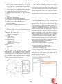
• In one terminal type: “rt_square –v” to run the executable
in Hard RTS mode with verbose output as in Fig. 9.
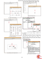
• In another terminal type: “xrtailab” to open a GUI &
from “File” menu select “Connect” and it will give the
option to set the target. Click on “OK” as shown in Fig.
10.
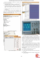
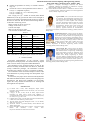
• A square wavelike wave form can be seen on the
Oscilloscope.
In xrtailab going to “View” select “parameters” and
“scope”. Now visualization parameters can be adjusted in the
“xrtailab” to see the square wave properly in to the
oscilloscope as shown in Fig. 11, 12.
Fig.11 Square wave in the scope of xrtailab
Fig.9 Running the Executable
Fig.12 Square wave in the Oscilloscope
C. Real-time speed control of dc motor using PWM
Pulse-width modulation (PWM) or duty-cycle variation
methods are commonly used in speed control of DC motors.
The duty cycle is defined as the percentage of digital „high‟ to
digital „low‟ plus digital „high‟ pulse-width during a PWM
period i.e. PWM the output voltage is the average of the
supplied voltage over ON/OFF time.
Fig.10 xrtailab Interface
Vav =Vs*D= (Ton*Vs)/(Ton+Toff)
When Vav=average voltage, D= duty cycle, Vs =Supply
Voltage, Ton=On time of the signal, Toff=Off time of the
Signal. Controlling the period (Ton+Toff) and on time (Ton) of
input pulses, the speed of the dc motor can be controlled as the
dc motor speed varies with the variation of the average
amplitude of input voltage to it. Steps to control the dc motor
are as follows:
Generate a real time square wave (Sec-IV).
Take that output signal from DAQ.
Fed that signal to the input section of a DC motor driver
(Sec. III).
Connect the DC motor driver output to the input of DC
motor (SEC. III).
361