1
User Manual
MOIR Insert Readers
USB HID
Interface Reference
11/30/2007
80068509-001
Rev. A
MOIR Insert Reader USB HID Reader Interface Reference
Table of Contents
1
Introduction............................................................................................ 3
2
INSTALLATION ..................................................................................... 3
3
USB COMMUNICATIONS..................................................................... 4
4
MOIR Data Structure ............................................................................. 5
4.1
ID TECH Format Data Structure .........................................................................5
4.2
Mag-Tek Format Data Structure..........................................................................5
4.3
Notes (for both IDTECH format and MagTek format): ......................................6
5
Descriptor Tables: ................................................................................. 6
5.1
Device Descriptor: ...............................................................................................6
5.2
Configuration Descriptor: ....................................................................................7
5.3
Interface Descriptor: ............................................................................................7
5.4
HID Descriptor: ...................................................................................................7
5.5
End Pointer Descriptor:........................................................................................8
5.6
Report Descriptor: (ID TECH Setting) ................................................................8
5.7
Report Descriptor: (MagTek Setting) ..................................................................9
6
HID USAGES: ..................................................................................... 10
6.1
IDTECH format reader usage page 0xff00:.......................................................10
6.2
Mag-Tek format reader usage page 0xff00:......................................................10
7
Command requests and responses:.................................................... 11
7.1
Commands .........................................................................................................11
7.2
Function ID ........................................................................................................12
7.3
Default and Available Setting............................................................................15
7.4
Notification Setting............................................................................................17
7.5
Notifications explain:.........................................................................................18
7.5.1
Card Seated Change Notification...............................................................18
7.5.2
Card Present Change Notification .............................................................18
7.5.3
No Data Notification..................................................................................18
7.5.4
Media Detected Notification......................................................................18
7.5.5
Magnetic Data Present Notification...........................................................18
7.5.6
Card in Slot Notification............................................................................18
7.5.7
Incomplete Insertion Notification ..............................................................18
7.6
Commands example:..........................................................................................19
7.6.1
Get Firmware Version................................................................................19
7.6.2
Setting Command.......................................................................................19
7.6.3
Get Setting .................................................................................................19
Copyright © 2006, International Technologies & systems Corporation. All rights reserved.
Page 2 of 19
MOIR Insert Reader USB HID Reader Interface Reference
1 Introduction
The MOIR USB HID Reader is a magnetic stripe card insert reader. The Reader is
compatible with the PC series of personal computers or any device with a USB
interface. To read a card on withdrawal (recommend) or insertion with the magnetic stripe
facing the magnetic head.
The reader conforms to the USB Human Interface Device (HID) Class specification Version
2.0. Host applications designed for the Second Edition of Windows 98, Me, 2000 and XP
can be easily communicate with the MOIR USB HID reader using standard Windows API
calls that communicate to the device through the HID driver that comes with Windows.
Unlike USB HID keyboard readers, this reader does not do keyboard emulation. It behaves
as a vendor defined HID device so that a direct communication path can be established
between the Host application and the device.
A Visual Basic demo program with its source code is available.
2 INSTALLATION
On hosts with the Windows operating system, the first time the device is plugged into a
specific USB port; Windows will pop up a dialog box, which will guide you through the
process of installing a device driver for the device. After this process is completed once,
Windows will no longer request this process as long as the device is plugged into the same
USB port. The device driver that Windows will install for this device is the driver used for
HID devices and it is part of the Windows operating system. Most Windows will find all the
files it needs on its own without giving you any prompts. Other times Windows will need to
know the location of the files it needs.
Copyright © 2006, International Technologies & systems Corporation. All rights reserved.
Page 3 of 19
MOIR Insert Reader USB HID Reader Interface Reference
3 USB COMMUNICATIONS
This device conforms to the USB specification revision 2.0. This device also conforms with
the Human Interface Device (HID) class specification version 1.1. The device
communicates to the host as a vendor defined HID device. The details about how the card
data and commands are structured into HID reports follow later in this section. The latest
versions of the Windows operating systems, Windows 98, Me, and 2000, all come with a
standard Windows USB HID driver. Windows applications that communicate to this device
can be easily developed. These applications can communicate to the device using
standard windows API calls that communicate to the device using the standard Windows
USB HID driver. These applications can be easily developed using compilers such as
Microsoft’s Visual Basic or Visual C++. A demonstration program and its source code,
written in Visual Basic, that communicates with this device is available. This demo program
can be used to test the device and it can be used as a guide for developing other
applications. More details about the demo program follow later in this document.
It is strongly recommended that application software developers become familiar with the
HID specification the USB specification before attempting to communicate with this
device. This document assumes that the reader is familiar with these
specifications. These specifications can be downloaded free from www. usb. org.
This is a full speed USB device. This device has a number of programmable configuration
properties. These properties are stored in non-volatile EEPROM memory. These
properties can be configured at the factory or by the end user. The device has an
adjustable endpoint descriptor polling interval value that can be set to any value in the
range of 1ms to 255ms. This property can be used to speed up or slow down the card data
transfer rate. The device will go into suspend mode when directed to do so by the
host. The device will wakeup from suspend mode when directed to do so by the host.
Copyright © 2006, International Technologies & systems Corporation. All rights reserved.
Page 4 of 19
MOIR Insert Reader USB HID Reader Interface Reference
4 MOIR Data Structure
MOIR USB HID Reader supports both ID TECH and Mag-Tek data Structure with an
EEPRom setting.
Vender ID: 0ACD
USB HID Data Format Setting:
Setting A: ID TECH Data Format (Default setting)
Product ID: 0640
Setting B: MagTek Data Format
Product ID: 0650
During first plug in, the Firmware will read the "Data Format Setting" from EEPROM and
send current Product ID in enumeration. Each time after change the "Data Format Setting",
the firmware will save the setting to EEPROM then re-do the enumeration process.
Command requests and responses are sent to and received from the device using feature
reports. Command is send to the device using HID class specific request Set_Report ( 21
09 …). The response to a command is retrieved from the device using HID class specific
request Get_Report (A1 01 …). These requests are sent over the default control pipe.
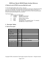
4.1 ID TECH Format Data Structure
Offset
Usage Name
0
T1 decode status
1
T2 decode status
2
T3 decode status
3
T1 data length
4
T2 data length
5
T3 data length
6
Card encode type
7,8
Total Output Length
9-508
Output Data
In this approach, the reader will keep all of the ID TECH data editing and other features like
preamble, postamble, etc. The output data is always 509 bytes; the "Total Output Length"
field indicates the valid data length in the output data.
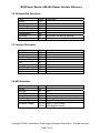
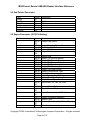
4.2 Mag-Tek Format Data Structure
Offset
0
1
2
3
4
5
6
7-116
117-226
227-336
Usage Name
T1 decode status
T2 decode status
T3 decode status
T1 data length
T2 data length
T3 data length
Card encode type
T1 data
T2 data
T3 data
Copyright © 2006, International Technologies & systems Corporation. All rights reserved.
Page 5 of 19
MOIR Insert Reader USB HID Reader Interface Reference
4.3 Notes (for both IDTECH format and MagTek format):
T1, T2 or T3 decode status: 0 for no error, 1 for error
T1, T2 or T3 Data Length: Each byte value indicates how many bytes of decoded card data
are in the track data field. This value will be zero if there was no data on the track or if
there was an error decoding the track. The track data includes all data string starting with
the start sentinel and ending with the end sentinel.
Card Encode Type:
Value
0
1
2
3
4
Encode Type Description
ISO/ABA
ISO/ABA encode format
AAMVA
AAMVA encode format
CADL
California Driver License
Blank
The card is blank
Other
The card has a non-standard format. For example,
ISO/ABA track 1 format on track 2
5 Descriptor Tables:
5.1 Device Descriptor:
Field
Length
Des type
bcd USB
Device Class
Sub Class
Device Protocol
Max Packet Size
VID
PID
BCD Device Release
i-Manufacture
i-Product
i-Serial-Number
# Configuration
Value
12
01
10 01
03
00
00
20
CD 0A
40 06
/ 50 06
00 01
01
02
00
01
Description
Unused
Unused
With ID TECH Structure
With MagTech Structure
Copyright © 2006, International Technologies & systems Corporation. All rights reserved.
Page 6 of 19
MOIR Insert Reader USB HID Reader Interface Reference
5.2 Configuration Descriptor:
Field
Length
Des type
Total Length
No. Interface
Configuration Value
iConfiguration
Attributes
Power
Value
09
02
22 00
01
01
00
80
32
Description
Bus power, no remove wakeup
100 mA
5.3 Interface Descriptor:
Field
Length
Des type
Interface No.
Alternator Setting
# EP
Interface Class
Sub Class
Interface Protocol
iInterface
Value
09
04
00
00
01
03
00
00
00
Description
HID
5.4 HID Descriptor:
Field
Length
Des type
bcdHID
Control Code
numDescriptors
DescriptorType
Descriptor Length
Value
09
21
11 01
00
01
22
37 00
3D 00
Description
HID
Number of Class Descriptors to follow
Report Descriptor
With ID TECH format
With MagTek format
Copyright © 2006, International Technologies & systems Corporation. All rights reserved.
Page 7 of 19
MOIR Insert Reader USB HID Reader Interface Reference
5.5 End Pointer Descriptor:
Field
Length
Des Type
EP Addr
Attributes
MaxPacketSize
bInterval
Value
07
05
81
03
20 00
0A
Description
End Point
EP1 - In
Interrupt
5.6 Report Descriptor: (ID TECH Setting)
Field
Value
06 00
FF
09 01
A1 01
15 00
26 FF
00
75 08
09 20
09 21
09 22
09 28
09 29
09 2A
09 38
95 07
81 02
09 30
95 02
82 02
01
09 31
96 F4
01
82 02
01
09 20
95 08
B2 02
01
C0
Description
Usage Page (MSR)
Usage(Decoding Reader Device)
Collection (Application)
Logical Minimum
Logical Maximum
Report Size
Usage (Tk1 Decode Status)
Usage (Tk2 Decode Status)
Usage (Tk3 Decode Status)
Usage (Tk1 Data Length)
Usage (Tk2 Data Length)
Usage (Tk3 Data Length)
Usage (Card Encode Type)
Report Count
Input (Data,Var,Abs,Bit Field)
Usage (Total Sending Length)
Report Count (2)
Input (Data, Var, Abs, Bit Field)
Usage (Output Data)
Report Count (500 )
Input (Data, Var, Abs, Bit Field)
Usage (Command Message)
Report Count
Feature (Data,Var, Abs, Buffered Bytes)
End Collection
Copyright © 2006, International Technologies & systems Corporation. All rights reserved.
Page 8 of 19
MOIR Insert Reader USB HID Reader Interface Reference
5.7 Report Descriptor: (MagTek Setting)
Field
Value
06 00
FF
09 01
A1 01
15 00
26 FF
00
75 08
09 20
09 21
09 22
09 28
09 29
09 2A
09 38
95 07
81 02
09 30
95 6E
82 02
01
09 31
95 6E
82 02
01
09 32
95 6E
82 02
01
09 20
95 08
B2 02
01
C0
Description
Usage Page (MSR)
Usage(Decoding Reader Device)
Collection (Application)
Logical Minimum
Logical Maximum
Report Size
Usage (Tk1 Decode Status)
Usage (Tk2 Decode Status)
Usage (Tk3 Decode Status)
Usage (Tk1 Data Length)
Usage (Tk2 Data Length)
Usage (Tk3 Data Length)
Usage (Card Encode Type)
Report Count
Input (Data,Var,Abs,Bit Field)
Usage (Tk1 Data)
Report Count (110)
Input (Data, Var, Abs, Bit Field)
Usage (Tk2 Data)
Report Count (110)
Input (Data, Var, Abs, Bit Field)
Usage (Tk3 Data)
Report Count (110)
Input (Data, Var, Abs, Bit Field)
Usage (Command Message)
Report Count
Feature (Data,Var, Abs, Buffered Bytes)
End Collection
Copyright © 2006, International Technologies & systems Corporation. All rights reserved.
Page 9 of 19
MOIR Insert Reader USB HID Reader Interface Reference
6 HID USAGES:
HID devices send data in reports. Elements of data in a report are identified by unique
identifiers called usages. The structure of the device’s reports and the device’s capabilities
are reported to the host in a report descriptor. The host usually gets the report descriptor
only once (after the device is plugged powered up). The report descriptor usages identify
the devices capabilities and report structures. For example, a device could be identified as
a keyboard by analyzing the device’s report descriptor. Usages are four byte integers. The
most significant two bytes are called the usage page and the least significant two bytes are
called usage IDs. Usages that are related can share a common usage page. Usages can
be standardized or they can be vendor defined. Vendor defined usages must have a usage
page in the range 0xff00 – 0xffff. All usages for this device are vendor defined magnetic
stripe reader usage page 0xff00. The usage IDs for this device are defined in the following
table. The usage types are also listed.
6.1 IDTECH format reader usage page 0xff00:
1
20
21
22
28
29
2A
38
30
31
20
Decoding reader device Collection None
Track 1 decode status
Data
Input
Track 2 decode status
Data
Input
Track 3 decode status
Data
Input
Track 1 data length
Data
Input
Track 2 data length
Data
Input
Track 3 data length
Data
Input
Card encode type
Data
Input
Total Data Length
Data
Input
Output Data
Data
Input
Command message
Data
Feature
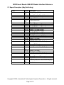
6.2 Mag-Tek format reader usage page 0xff00:
Usage ID
(Hex)
1
20
21
22
28
29
2A
30
31
32
38
20
Usage Name
Decoding reader device
Track 1 decode status
Track 2 decode status
Track 3 decode status
Track 1 data length
Track 2 data length
Track 3 data length
Track 1 data
Track 2 data
Track 3 data
Card encode type
Command message
Usage Type Report Type
Collection
Data
Data
Data
Data
Data
Data
Data
Data
Data
Data
Data
None
Input
Input
Input
Input
Input
Input
Input
Input
Input
Input
Feature
Copyright © 2006, International Technologies & systems Corporation. All rights reserved.
Page 10 of 19
MOIR Insert Reader USB HID Reader Interface Reference
7 Command requests and responses:
Command requests and responses are sent to and received from the device using feature
reports. Command is send to the device using HID class specific request Set_Report ( 21
09 …). The response to a command is retrieved from the device using HID class specific
request Get_Report (A1 01 …). These requests are sent over the default control pipe.
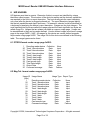
7.1 Commands
A simple Turbo TLP-224 protocol with one byte check sum is used when host
communicates with reader.
Command is in format of <ACK> <Length> <Command> <LRC> <ETX>
Positive response of reader will be in format of <ACK> <Length> <Data> <LRC> <ETX>
Negative response from a reader will be in format of <NAK> <Length> <Status> <LRC>
<ETX>
Where:
<ACK> is 60h.
<NACK> is E0h.
<Length> is a two-byte counter of length of <Command>.
<Status> is a two-byte error code.
<ETX> is 03h.
The overall <LRC> (Modulus 2 = Exclusive OR) checksum (from <60> to <LRC>) should
be zero.
The following table is a summary of error code.
<29> <00> Unknown Function ID (or Function Value) in setting command
<2A> <00> Command received correctly, but could not complete
<69> <00> Command not supported
<81> <00> Time out
The response for Unknown function ID or Function Value will be in format of <NAK>
<Length> <29> <00> <Unknown ID Num> <Unknown ID 1> . . . <LRC> <ETX>
Firmware will still do all the setting for known setting unless communication protocol is
wrong.
Copyright © 2006, International Technologies & systems Corporation. All rights reserved.
Page 11 of 19
MOIR Insert Reader USB HID Reader Interface Reference
The following table is a summary of the general commands.
Command
24
Name
Get Reader Status
39
49
50 01 30
50 01 32
51 01 <Track Selection Option>
52 <FunctionID>
Get Firmware
Version
Reader Reset
Arm to Read
MSR Reset
Read MSR Data
Get Setting
52 1F
Get All Settings
53 18
Default all
53 [<FuncID> <Len>
<FuncData>]. . .
<6C> <LED Status>
Send Setting
LED Control
Usage
To get reader status in form
of a single byte
To get the version of the
reader's firmware
Reset the reader
Buffer mode set
Buffer mode reset
Read stored MSR data
Getting various reader
optional settings
Getting all current settings
of the reader
Setting reader optional
functions to default
Setting various reader
optional functions
Turning on/off bicolor LED
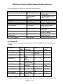
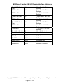
7.2 Function ID
Function ID used in command/response are same as MiniMag I ID and they defined as
follows:
Function ID
HTypeID
ReaderOptID
Hex
Value
10
11
Function
Description
Terminal Type
Reader Option
CharDelayID
12
TrackSelectID
13
PollingIntervalID
14
TrackSepID
17
DefaultAllID
18
Character
Delay
Track
Selection
USB HID
Polling Interval
Track
Separator
Default All
SendOptionID
19
Send Option
MSRReadingID
DecodingMethodID
1A
1D
MSR Reading
MSR Decode
Method
Default
'0'
8Fh (RS232)
/03h (KB)
'0'
Function
Value
'0','5','6'
Any
'0' - '5'
'0'
'0' - '7'
1
1 ~ 255 ms
\CR
Any ASCII
Code
'1' (RS232) / ‘5’
(KB)
'1'
'3'
'0' - '7'
'0' - '2'
'1' - '3'
Copyright © 2006, International Technologies & systems Corporation. All rights reserved.
Page 12 of 19
MOIR Insert Reader USB HID Reader Interface Reference
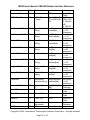
ReviewID
1F
Review All
TerminatorID
21
Terminator
USBHIDFmtID
23
CardSeatedStrID
26
CardRemovedStrID
27
CardInStrID
28
CardOutStrID
29
NoDataStrID
2A
MediaDetectedStrID
2B
MagDataStrID
2C
CardInSlotStr
2D
PartialInStr
2E
ReaderOpt2ID
2F
Track1ID
31
Track2ID
32
Track3ID
33
LZ1ID
3C
LZ2ID
3D
\CR
Any ASCII
Code
USB HID
‘0’ for USB HID ‘0’ ID
Format
‘8’ for USB HID TECH HID
KB
‘1’ MagTek
HID
‘8’ HID KB
Card Seated
[tab]Card
Any String
String
Seated[tab]
(<= 23
characters)
Card Removed [tab]Card
Any String
String
Removed[tab]
(< = 23
characters)
Card Present
[tab]Card
Any String
String
Present[tab]
(<= 23
characters)
Card Out
[tab]Card
Any String
String
Out[tab]
(<= 23
characters)
No Data String [tab]No
Any String
Data[tab]
(<= 23
characters)
MediaDetected [tab]Media
Any String
String
Detected[tab]
(<= 23
characters)
Magnetic Data [tab]Magnetic
Any String
String
Data[tab]
(<= 23
characters)
Card In Slot
[tab]Card In
Any String
String
Slot[tab]
(<= 23
characters)
Incomplete
[tab]Incomplete Any String
Insertion String Insertion[tab]
(<= 23
characters)
Reader Option 00h(RS232)/03h Any
2
(KB)
Character
Track 1 ID
NULL
Any ASCII
Code
Track 2 ID
NULL
Any ASCII
Code
Track 3 ID
NULL
Any ASCII
Code
T1 Lead zero
0Dh
Any
adjustment
Character
T2 Lead zero
0Dh
Any
Copyright © 2006, International Technologies & systems Corporation. All rights reserved.
Page 13 of 19
MOIR Insert Reader USB HID Reader Interface Reference
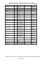
LZ3ID
3E
BaudID
DataID
ParityID
HandShakeID
41
42
43
44
StopID
XOnID
45
47
XOffID
48
LRCID
T17BStartID
60
61
T16BStartID
62
T15BStartID
63
T27BStartID
64
T25BStartID
65
T37BStartID
66
T36BStartID
67
T35BStartID
68
TEndID
69
BTModeID
70
PrefixID
PostfixID
D2
D3
adjustment
T3 Lead zero
adjustment
Baud Rate
Data Bit
Data Parity
Handshake
mode
Stop Bit
X-On
Character
X-Off
Character
LRC Character
Track 1 7 Bit
Start Sentinel
Track 1 6 Bit
Start Sentinel
Track 1 5 Bit
Start Sentinel
Track 2 7 Bit
Start Sentinel
Track 2 5 Bit
Start Sentinel
Track 3 7 Bit
Start Sentinel
Track 3 6 Bit
Start Sentinel
Track 3 5 Bit
Start Sentinel
End Sentinel
Boot loader
Mode
Prefix Setting
Postfix Setting
0Dh
'7'
'0'
'0'
'0'
'0'
11h
Character
Any
Character
'0' - '7'
'0' - '1'
'0' ~ '4'
'0' - '2'
00h
'0' - '1'
Any ASCII
Code
Any ASCII
Code
'0' ~ '1'
Any
Character
Any
Character
Any
Character
Any
Character
Any
Character
Any
Character
Any
Character
Any
Character
Any
Character
FFh
NULL
NULL
String
String
13h
'0'
'%'
'%'
';'
'%'
';'
'%'
'!'
';'
'?'
Copyright © 2006, International Technologies & systems Corporation. All rights reserved.
Page 14 of 19
MOIR Insert Reader USB HID Reader Interface Reference
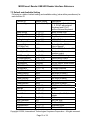
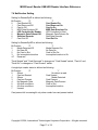
7.3 Default and Available Setting
Following is a table of default setting and available setting (value within parentheses) for
each function ID.
Function ID
Terminal Type
Default Setting
'0' (‘0’~’2’,'4'~'6')
Beep Setting
Character Delay
Track Selection
Polling Interval
Data Output Format
Format Option
(UIC/Mag-Tek)
Track Separator
SendOptionID
‘2’ (‘0’~’2’)
‘0’ (‘0’~’5’)
‘0’ (‘0’~’9’)
1 (1 ~ 255)
‘0’ (‘0’~’2’)
H’59’
CR/Enter
‘1’ (‘0’~’F’)
MSRReadingID
DTEnableSendID
DecodingMethodID
TerminatorID
USBHIDFmtID
ForeignKBID
Track1PrefixID
Track2PrefixID
Track3PrefixID
Track1SuffixID
Track2SuffixID
Track3SuffixID
Baud Rate
Data Bit
Data Parity
Hand Shake
‘1’ (‘0’~’2’)
‘0’(‘0’,’1’,’3’)
‘1’ (‘0’~’3’)
CR/Enter
‘0’ (‘0’~’1’)
'0' ('0' ~ '9')
NULL
NULL
NULL
NULL
NULL
NULL
‘5’ (‘3’~’7’)
‘0’ (‘0’~’1’)
‘0’ (‘0’~’4’)
‘0’ (‘0’~’1’)
Stop Bit
XOn Character
XOff Character
OutputModeID
LRC character
‘0’ (‘0’~’1’)
DC1
DC3
'0' ('0' ~ '1')
‘0’ (‘0’~’1’)
Description
PC/AT, Scan Code Set 2,
1, 3, PC/AT with external
Keyboard and PC/AT
without External Keyboard
Beep volume High
2 ms inter-character delay
Any Track
USB HID Polling Interval
ID TECH Format
Refer MiniMag RS232
User’s Manual
CR for RS232, Enter for KB
Sentinel and Account
number control
Enable MSR Reading
Data Editing Control
Decoding in both direction
CR for RS232, Enter for KB
ID TECH Format
Foreign Keyboard
No prefix for track 1
No prefix for track 2
No prefix for track 3
No suffix for track 1
No suffix for track 2
No suffix for track 3
9600 bps, ‘7’ is 38,400 bps
8 Bits
None
Software (Xon/Xoff) hand
shake
1 Bit
0x11 as XOn
0x13 as XOff
Standard mode
Without LRC in output
Copyright © 2006, International Technologies & systems Corporation. All rights reserved.
Page 15 of 19
MOIR Insert Reader USB HID Reader Interface Reference
Track 1 7 Bit Start
Char
T16BStartID
‘%’
‘%’
T15BStartID
‘;’
Track 2 7 Bit Start
Char
T25BStartID
‘%’
‘;’
Track 3 7 Bit Start
Char
T36BStartID
‘%’
‘!’
T35BStartID
‘;’
Track 1 End Sentinel
Track 2 End Sentinel
Track 3 End Sentinel
PrefixID
PostfixID
AddedFieldID
SearchCmdID
SendCmdID
‘?’
'?'
'?'
NULL
NULL
NULL
NULL
NULL
‘%’ as Track 1 7 Bit Start
Sentinel
‘%’ as Track 1 6 Bit Start
Sentinel
‘;’ as Track 1 5 Bit Start
Sentinel
‘%’ as Track 2 7 Bit Start
Sentinel
‘;’ as Track 2 5 Bit Start
Sentinel
‘%’ as Track 3 7 Bit Start
Sentinel
‘!’ as Track 3 6 Bit Start
Sentinel
‘;’ as Track 3 5 Bit Start
Sentinel
‘?’ as End Sentinel
‘?’ as End Sentinel
‘?’ as End Sentinel
No Prefix
No Postfix
No Added Field
No Search Command
No Send Command
Copyright © 2006, International Technologies & systems Corporation. All rights reserved.
Page 16 of 19
MOIR Insert Reader USB HID Reader Interface Reference
7.4 Notification Setting
Setting for ReaderOptID is defined as following:
Bit Position
'0'
'1'
0
Card Seated Off
Card Seated On
1
Card Removed Off
Card Removed On
2
Card In Off
Card In On
3
MSR Data Envelope Off
MSR Data Envelope On
4
LED Controlled by Reader
LED Controlled by Host
5
Magnetic Data Present Off
Magnetic Data Present On
6
Standard Decoder
Raw Data Decoder
7
Card Out Off
Card Out On
Setting for ReaderOpt2ID is defined as following:
Bit Position
'0'
'1'
0
Media Detected Off
Media Detected On
1
No Data Off
No Data On
2
No Card in Slot
Card in Slot On
3
No Imcomplete Insertion
Incomplete Insertion is On
4-7
Reserved
"Card Seated" and "Card Removed" is changes on "Card Seated" switch, "Card In" and
"Card Out" is changes on "Card Present" switch.
A single byte reader status is defined as following:
Bit Position
'0'
'1'
0
Others
No data in a read
1
Card not Seated
Card Seated
2
Others
Media Detected
3
Card not Present
Card Present
4
No Magnetic Data
Magnetic Data Present
5
All other conditions
Card in Slot
6
All other conditions
Incomplete Insertion
7
Unused
Card present bit is meaningful only when reader has card present switch.
Copyright © 2006, International Technologies & systems Corporation. All rights reserved.
Page 17 of 19
MOIR Insert Reader USB HID Reader Interface Reference
7.5 Notifications explain:
7.5.1 Card Seated Change Notification
Switch change notification on card seated switch will be issued if its setting is on.
"Card Seated On and Off" and "Card Removed On and Off" in ReaderOptID is used to
enable or disable notification about card seated switch change.
7.5.2 Card Present Change Notification
Switch change notification on card present switch will be issued if its setting is on.
"Card In On and Off" and "Card Out On and Off" in ReaderOptID is used to enable or
disable notification about card present switch change.
7.5.3 No Data Notification
No data after an insertion or withdrawal will be issued if its setting is on. They are
mismatch of data edit formula, no data on selected tracks if read direction is enabled and
magnetic data envelop is off, no magnetic data after an insertion or withdraw time out.
7.5.4 Media Detected Notification
Media Detected Notification after an insertion or withdrawal will be issued if its setting is on
and magnetic data in current read direction disabled by reader.
7.5.5 Magnetic Data Present Notification
Magnetic Data Present Notification after an insertion or withdrawal will be issued if in buffer
mode; its setting is on and magnetic data in current read direction enabled by reader.
7.5.6 Card in Slot Notification
Card in Slot notification after a withdrawal will be issued if card present still on after 2
second of withdrawal.
7.5.7 Incomplete Insertion Notification
Incomplete Insertion notification after an insertion will be issued if card seated still off after
2 second of insertion.
Copyright © 2006, International Technologies & systems Corporation. All rights reserved.
Page 18 of 19
MOIR Insert Reader USB HID Reader Interface Reference
7.6 Commands example:
7.6.1 Get Firmware Version
This command will respond a firmware version to application.
Command: <ACK> <Length> <R> <FmVerID> <LRC 1> <ETX>
Response: <STX> <Firmware Version String> <LRC 2> <ETX>
Version String will be in format of “ID TECH Magnetic Stripe Insert zzz Reader
Vxx. yy. xx. yy is the major and minor version number; zzz is the interface, it can be
“RS232”, “Keyboard”, “USB HID KB”, “USB HID” or “USB CDC”.
7.6.2 Setting Command
The setting data command is a collection of many function setting blocks and its format is
as follows.
Command: <ACK> <Length> <S> <FuncSETBLOCK1>…<FuncBLOCKn> < LRC> <ETX>
Response: <ACK> or <NAK> for wrong command (invalid funcID, length and value)
Each function-setting block <FuncSETBLOCK> has following format:
<FuncID><Len><FuncData>
Where:
<FuncID> is one byte identifying the setting(s) for the function.
<Len> is a one byte length count for the following function-setting block <FuncData>.
<FuncData> is the current setting for this function. It has the same format as in the sending
command for this function.
7.6.3 Get Setting
This command will send current setting to application.
Command: <ACK> <Length> <R> <FuncID > <LRC 1> <ETX>
Response: <STX> <Current Setting> <LRC 2> <ETX>
<FuncID>, <Len> and <FuncData> definition are same as described above.
Copyright © 2006, International Technologies & systems Corporation. All rights reserved.
Page 19 of 19