1
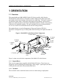
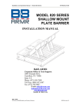
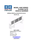
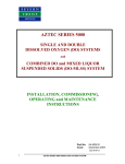
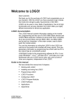
MODEL 850 SERIES TOWABLE VEHICLE BARRIER INSTALLATION MANUAL B&B ARMR Corporate Office & Tech Support: 2009 Chenault Drive Carrollton, TX 75006 Suite 114 Phone: (972) 385-7899 Toll Free: (800) 367-0387 Fax: (972) 385-9887 E-mail: [email protected] [email protected] www.bb-armr.com MADE IN THE USA B&B ARMR A Division of B&B Roadway and Security Solutions 0850-9001 Revision F2 Installation and Operations Manual — Model 850 Series INTRODUCTION Your safety is extremely important to us. If you have any questions or are in doubt about any aspect of the equipment, please contact us. INTRODUCTION Welcome! Congratulations on your purchase of a B&B ARMR vehicle barrier. In addition to providing detailed operating instructions, this manual describes how to install, maintain, and troubleshoot your vehicle barrier. If you require additional assistance with any aspect of your vehicle barrier's installation or operation, please contact us. We have years of experience in all aspects of perimeter security and related disciplines, and our products are used throughout the world to control access and to protect people, equipment, and facilities. We offer a broad range of vehicle barrier and related security services: Turnkey installations Routine barrier preventative maintenance or emergency repairs (including work on non-B&B ARMR products) Spare or replacement parts Custom designs or special installations Equipment upgrades (modernize your old equipment with state-of-the-art hydraulics and control systems) Ancillary security equipment such as security guard enclosures, card readers, security lighting, and many other security related products. Safety B&B ARMR A Division of B&B Roadway and Security Solutions 0850-9001 Revision F2 ii Installation and Operations Manual — Model 850 Series INTRODUCTION B&B ARMR does not assume responsibility for injury to persons or property during installation, operation, or maintenance. As the user, you are responsible for correct and safe installation, operation, and maintenance of this equipment. Users must follow the specific instructions and safety precautions located in this manual. In addition they must: Follow the safety standards of the Occupational Safety and Health Administration (OSHA), as well as other applicable federal, state, and local safety regulations and industry standards and procedures. For installation outside the United States, users must also follow applicable international, regional, and local safety standards. Engage only trained and experienced staff to install, operate, and maintain the equipment. Ensure that all repairs are performed correctly, using properly trained technicians and the correct tools and equipment. The Model 850 Towable Barrier is developed for portability for low tow speed applications only. For use in high speed applications, please contact B&B ARMR sales. How to Contact Us If you have any questions or experience any problems with your vehicle barrier—or if we can help you with any other facility security issues—please contact us directly at: Corporate/Tech Support: B&B ARMR 2009 Chenault Drive Suite 114 Carrollton, TX 75006 USA Telephone: (972) 385-7899 Toll Free: (800) 367-0387 Fax: (972) 385-9887 E-mail: [email protected] [email protected] B&B ARMR A Division of B&B Roadway and Security Solutions 0850-9001 Revision F2 iii Installation and Operations Manual — Model 850 Series TABLE OF CONTENTS Table of Contents INTRODUCTION........................................................................................................ii Safety ..............................................................................................................................ii How to Contact Us ...................................................................................................... iii 1 ORIENTATION ................................................................................................... 5 1.1 Overview .......................................................................................................................................... 5 1.1.1 Support Brace ......................................................................................................................... 5 1.1.2 Tow Hitch ............................................................................................................................... 5 1.1.3 Storage Cabinet....................................................................................................................... 6 1.1.4 Power Cabinet......................................................................................................................... 6 1.1.5 Control Station ........................................................................................................................ 6 1.1.6 Jack handle ............................................................................................................................. 6 1.1.7 Brace Plate .............................................................................................................................. 6 1.1.8 Attack plate ............................................................................................................................. 6 1.1.9 Wheels .................................................................................................................................... 6 1.1.10 Options ............................................................................................................................... 6 2 INSTALLATION .................................................................................................. 7 2.1 Introduction ...................................................................................................................................... 7 2.2 Pre-Operation .................................................................................................................................. 8 2.2.1 Component Inspection ............................................................................................................ 8 2.2.2 Hydraulic Fluid Check ............................................................................................................ 8 2.2.3 Electrical Hook-up .................................................................................................................. 9 2.2.4 Control Hook-up ..................................................................................................................... 9 2.2.5 Flow Control Valve Adjustment ............................................................................................10 2.3 Towing/Deployment ........................................................................................................................11 2.3.1 Towing Preparation ...............................................................................................................11 2.3.2 Field Deployment ..................................................................................................................13 3 TROUBLESHOOTING ..................................................................................... 14 3.1 Model 850 Troubleshooting Guide..................................................................................................14 4 WARRANTY ........................................................................................................ 15 5 SYSTEM DIAGRAMS ......................................................................................... 16 5.1 Electrical Diagram – 220VAC with Battery Backup .......................................................................16 5.2 Control Station Wiring ....................................................................................................................17 5.3 Hydraulic Diagram .........................................................................................................................18 B&B ARMR A Division of B&B Roadway and Security Solutions 0850-9001 Revision F2 5 Installation and Operations Manual — Model 850 Series ORIENTATION 5 1 ORIENTATION 1.1 Overview This manual addresses B&B ARMR’s Model 850 Series towable vehicle barriers. The Model 850 vehicle barrier is designed to contain a high-speed vehicle impact and prevent that vehicle from entering a restricted access control area. The barrier consists of a towable base plate frame, raising plate with support locking linkage, and associated hardware to allow the plate to move from a horizontal position to a raised, secure position with the aid of a hydraulic cylinder. The unit is designed to be moved into position by use of a tow vehicle or fork lift and lowered onto the existing roadway. The standard barrier is tested to Department of State specifications STD 02.01. The barrier is designed to stop a 15,000-pound vehicle traveling at 30 mph in less than 50 feet. Figure 1: Model 850 Towable Barrier Basic Components 4. Power cabinet 5. Control Station 3. Storage cabinet 6. Jack handle 1. Support brace 8. Attack plate 9. Wheels 2. Tow hitch 7. Brace plate Attack Direction Figure 1 orients you to the basic components of the Model 850 vehicle barrier: 1.1.1 Support Brace There are two support braces supplied with the Model 850 barrier. These braces are designed to assist in stabilizing the unit during a vehicle impact. Upon impact, the braces will dig into the road surface directly behind the barrier. 1.1.2 Tow Hitch The tow hitch is used to attach the barrier to the tow vehicle during re-deployment. B&B ARMR A Division of B&B Roadway and Security Solutions 0850-9001 Revision F2 Installation and Operations Manual — Model 850 Series ORIENTATION CAUTION: Ensure vehicle has adequate capability to support and tow the barrier. Barrier should be towed at safe speed at all times. 1.1.3 Storage Cabinet The storage cabinet is supplied to allow easy storage for wheel pins, jack handles and supporting maintenance tools. 1.1.4 Power Cabinet The power cabinet houses the electronics and hydraulics to operate the vehicle barrier. DANGER: High voltage electrical components are located in cabinet. Service by qualified technicians only. CAUTION: Hydraulic linkages are located in cabinet. Do not operate barrier with cabinet door open. 1.1.5 Control Station The control station has an UP, DOWN, and STOP control buttons to operate the gate. 1.1.6 Jack handle The jack handle is used to rotate the lifting jacks. The handle is universally designed to allow rotation on either the attack side or safe side of barrier. 1.1.7 Brace Plate The brace plate is a non-removable plate used to brace the attack plate during a vehicle impact. 1.1.8 Attack plate The attack plate lifts and lowers using the hydraulic linkages. When the attack plate is in the down position, vehicle access is allowed. When deployed (UP), the attack plate ensures vehicles can not pass. 1.1.9 Wheels The wheels on the product are used to allow the product to be towed behind an adequate vehicle. Ensure wheels and axles have been installed correctly, secured and checked prior any movement of the barrier. 1.1.10 Options The Model 850 vehicle barrier is available with several options. Consult your order’s documentation to determine whether your unit has the optional equipment. B&B ARMR A Division of B&B Roadway and Security Solutions 0850-9001 Revision F2 6 Installation and Operations Manual — Model 850 Series ORIENTATION A traffic control gate arm to warn the vehicle operator. This arm is positioned in front of the gate and does not rise until the gate is fully open, and it closes before the gate starts to close Red/amber traffic lights. The light remains red if the gate is in any position except fully open Infrared safety beams to detect pedestrian traffic or as an additional vehicle sensing device Heater for the electric or hydraulic system Battery backup Diesel backup generator system 2 INSTALLATION 2.1 Introduction This section of the manual describes the procedure to set-up and configures the Model 850 Towable vehicle barrier for first-time operation. The product ships from the factory tested and ready for deployment following these steps. DANGER: High voltage electrical components are located in cabinet. Service by qualified technicians only. CAUTION: Heavy components and pinch points are present in this product. Use extreme care when servicing this unit. NOTE: The hydraulic hoses are constructed with JIC fittings to allow removal and installation without sealant. Care should be used when disconnecting any hose to insure the pressure has been released prior to disconnecting the fitting. The pressure can be relieved by activating the DOWN control button and visually watching the barrier go completely DOWN. If the hydraulic cylinder does not fully retract, the hose may still be under pressure. Once fully DOWN, press the STOP button to de-energize the spring-to-center valve, and relieve the system of any pressure. Prior to working on unit in UP position, insert supplied Safety Lock Pin to ensure attack plate does not move inadvertently. B&B ARMR A Division of B&B Roadway and Security Solutions 0850-9001 Revision F2 7 Installation and Operations Manual — Model 850 Series 8 Safety Pin Figure 2: Safety Lock Pin Location 2.2 Pre-Operation 2.2.1 Component Inspection Your model 850 Towable vehicle barrier is shipped from the factory with the following standard components (See table). It is recommended these items are inspected upon receipt to ensure installation and deployment time is minimized. Refer to shipping documents for other optional items that may have been included. Please contact B&B ARMR support if any items are missing or damaged. Item Number 1 2 3 4 5 6 7 8 9 10 11 2.2.2 Part Number Description Quantity 0850-1001 0850-2006-1 0850-2006 0850-3019 0850-2022 0850-2025 XPIN-90146A212 0850-3114 XHANDLE-LG0083-03 0850-9001 22575R15WRA Main Assembly Outrigger Support Brace- Right Outrigger Support Brace- Left Outrigger Brace Retaining Pin Control Station Shaft Assembly/Hub Wheel Assembly Lock Pin Safety Lock Pin Jack handle User Manual Wheel 1 1 1 2 1 4 4 2 2 1 4 Hydraulic Fluid Check Prior to initial operation, exchange breather plug and shipping plug in hydraulic reservoir. B&B ARMR A Division of B&B Roadway and Security Solutions 0850-9001 Revision F2 Installation and Operations Manual — Model 850 Series 9 The product is normally shipped from the factory ready for deployment. In some situations the fluids have been drained to accommodate shipping methods. Prior to electrical hook-up, verify the hydraulic fluid levels. If required, add hydraulic fluid. We recommend using environmentally safe oil Mobil EAL 224 or equivalent. 2.2.3 Electrical Hook-up The hydraulic pumping unit is a complete assembly which contains both the mechanical components and electrical components necessary to make the unit operate. Do not power the unit until all traffic and pedestrians have been cleared from harms way. Please refer to the appropriate wiring diagram that matches your specific product. A wiring diagram is located in the appendix. In case of main power electrical failure, the barrier may be equipped with an optional battery backup. 2.2.4 Control Hook-up This barrier includes a control station to raise, lower, and stop the barrier. To install; connect to connector mounted in side of barrier stanchion (see figure 3). Figure 3: Control Station and connectors B&B ARMR A Division of B&B Roadway and Security Solutions 0850-9001 Revision F2 Installation and Operations Manual — Model 850 Series 2.2.5 10 Flow Control Valve Adjustment The POWERED DOWN FLOW VALVE allows the DOWN speed to be adjusted. It is recommended the down speed be adjusted to allow the attack plate to come down as slow as the application will allow. Normal DOWN speed is 6-8 seconds which corresponds to the blue colored ring on the flow valve. The MANUAL DOWN FLOW VALVE should remain in the fully closed position for normal operation. Open this valve slowly for manual down operation. The MANUAL BY_PASS BALL VALVE to enable the hand pump for manual operation. It should normally be left in the vertical position to shut off the hand pump. The up speed of the barrier is not adjustable, and may range between 10-17 seconds. MANUAL BY-PASS BALL VALVE MANUAL DOWN FLOW VALVE POWERED DOWN FLOW VALVE Figure 4: Valve and Hose Configuration B&B ARMR A Division of B&B Roadway and Security Solutions 0850-9001 Revision F2 Installation and Operations Manual — Model 850 Series 11 2.3 Towing/Deployment The Model 850 barrier is designed to be a towable barrier. Four wheel-axle assemblies are included with the product. DANGER: High voltage/current electrical components are located in cabinet. Service by qualified technicians only. CAUTION: Heavy components and pinch points are present in this product. Use extreme care when servicing this unit. 2.3.1 Towing Preparation Prior to towing, verify towing vehicle has capacity to tow at least 11,000 lbs. Check all tire pressure, bearing lubrication and assure all loose parts and equipment are stowed. The following are the steps required to prepare the product for movement. Step 1: Verify attack plate is in the DOWN position and remove electrical power from the barrier. Unplug control station and traffic light and stow in cabinet. Step 2: Remove left and right support braces by pulling out support brace pins. If pins are tight, slightly jacking unit up may help. B&B ARMR A Division of B&B Roadway and Security Solutions 0850-9001 Revision F2 Installation and Operations Manual — Model 850 Series 12 Step 3: Verify jack cross bar is installed. Jack up unit by rotating the shafts using the supplied jack handles. Unit may be raised by rotating the shafts from both the attack side and safe side. Verify rotation is correct and unit is lifting off ground. Unit must be raised a minimum of 15 inches off the ground to allow wheels and shafts to be installed. Step 4: On first time use, install wheels onto wheel shafts and hubs. Torque lug nuts to 100 ft-lbs. Install shafts and wheels into wheel hubs and secure with wheel lock pins. Wheels may stay attached to shafts and hubs on subsequent use. Step 5: B&B ARMR A Division of B&B Roadway and Security Solutions 0850-9001 Revision F2 Installation and Operations Manual — Model 850 Series 13 Lower unit by rotating jack handles in opposite direction. Raise jacks into stow position. Remove jack handles and stow in storage cabinet. Step 6: Secure safety pins in storage cabinet. Close and secure cabinet doors. The product is ready for movement. 2.3.2 Field Deployment Barrier deployment is similar to towing preparations, but in reverse. NOTE: It is extremely important that the barrier is installed on a level surface. Surface must be flat within ½ inch across the entire expanse. Clean surface site of all non-uniform rocks and debris that may cause unit to deform when lowered. Before operating the Model 850 vehicle barrier, go through the checklist below and verify that each of these steps has been completed. CAUTION: For your safety, complete each of these steps before operating the barrier! Verify pad site is flat Verify unit has hydraulic fluid to recommended level Verify control unit is plugged in and cable is routed clear of barrier operation DO NOT CONNECT OR DISCONNECT THE BATTERIES WITH AC POWER ON Verify area is clear of personnel and other obstructions Stow wheels in safe location Ensure supplied power matches product requirements Verify electrical hookups are completed per electrical wiring diagram matching unit It is recommended the unit be cycled 4 complete cycles prior to vehicle traffic B&B ARMR A Division of B&B Roadway and Security Solutions 0850-9001 Revision F2 Installation and Operations Manual — Model 850 Series TROUBLESHOOTING 3 TROUBLESHOOTING The table below provides guidance on identifying and correcting any problems with your Model 850 Series vehicle barrier. If you encounter problems that you cannot fix, contact B&B ARMR and we will gladly work with you to correct them. To see inputs on PLC: From Time/Date screen, press right arrow button. There will be an “I” followed by 3 rows of numbers. The numbers that are highlighted are ON. 3.1 Model 850 Troubleshooting Guide Symptom Barrier does not raise Barrier does not lower Actions Check power Verify UP turns on I1 on PLC Verify ‘MOTOR’ breaker is on Verify manual bypass valve is closed Check thermal overload (resettable) Verify there are no safety devices active Check power Verify DOWN turns on I2 on PLC Verify ‘MOTOR’ breaker is on Verify manual bypass valve is closed Check thermal overload (resettable) Check for obstacles under plate Barrier moves down too slowly (up speed is fixed and non-adjustable) Check flow control valve Traffic indicator light does not change Check proper limit switch operation Check bulbs B&B ARMR A Division of B&B Roadway and Security Solutions 0850-9001 Revision F2 14 Installation and Operations Manual — Model 850 Series 15 4 WARRANTY BBRSS warranties for a period of one (1) year FOB manufacturing facility, unless otherwise specified by BBRSS in writing, from defects due to faulty material or workmanship. Damage due to handling during shipment and installation are not covered under warranty. BBRSS assumes no responsibility for service at customer site. BBRSS is in no event responsible for any labor costs under the warranty. Subject to the above limitation, all service, parts, and replacements necessary to maintain the equipment as warranted shall be furnished by others. BBRSS shall not have any liability under these specifications, other than for repair or replacement as described above for faulty product material or workmanship. Equipment malfunction or equipment failure of any kind, caused for any reason, including, but not limited to unauthorized repairs, improper installation, installation not performed by BBRSS authorized personnel, incoming supply power is outside the tolerance for the product, failure to perform manufacturer’s suggested preventative maintenance, modifications, misuse, accident, catastrophe, neglect, natural disaster, are not under warranty. The exclusive remedy for breach of any warranty by BBRSS shall be the repair or replacement at BBRSS’s option, of any defects in the equipment. IN NO EVENT SHALL BBRSS BE LIABLE FOR CONSEQUENTIAL OR SPECIAL DAMAGES OR ANY KIND OF PERSONAL DAMAGES. Except as provided herein, BBRSS makes no warranties or representations to consumer or to anyone else and consumer hereby waives all liability against BBRSS as well as any other person for the design, manufacture, sale, installation, and/or servicing of the Products. THE FOREGOING WARRANTIES ARE IN LIEU OF ALL OTHER WARRANTIES EXPRESS OR IMPLIED, INCLUDING THE IMPLIED WARRANTY OF MERCHANTABILITY AND FITNESS FOR A PARTICULAR PURPOSE. NO OTHER WARRANTIES EXIST. Any modification or alteration by anyone other than BBRSS will render the warranty herein as null and void. B&B ARMR A Division of B&B Roadway and Security Solutions 0850-9001 Revision F2 Installation and Operations Manual — Model 850 Series 16 5 SYSTEM DIAGRAMS 6ED1 055-1MB00-0BA1 RUN/STOP B&B ARMR A Division of B&B Roadway and Security Solutions 12/24 RC LOGO! SIEMENS ESC OK DM8 12/24R 5.1 Electrical Diagram – 220VAC with Battery Backup 0850-9001 Revision F2 Installation and Operations Manual — Model 850 Series 17 5.2 Control Station Wiring B&B ARMR A Division of B&B Roadway and Security Solutions 0850-9001 Revision F2 Installation and Operations Manual — Model 850 Series 18 5.3 Hydraulic Diagram B&B ARMR A Division of B&B Roadway and Security Solutions 0850-9001 Revision F2 Installation and Operations Manual — Model 850 Series 19 Equipment Maintenance Log Form Product Type:________________________ B&B ARMR 800-367-0387 Location:____________________________ Jan Checklist Complete Yes No Feb Yes No Mar Yes No Apr Yes No May Yes No Jun Yes No Jul Yes No Aug Yes No Sep Yes No Oct Yes No Nov Yes No Year Yes No Date Date Performed By Performed By Checklist Complete Jan Yes No Feb Yes No Mar Yes No Apr Yes No May Yes No Jun Yes No Jul Yes No Aug Yes No Sep Yes No Oct Yes No Nov Yes No Year Yes No B&B ARMR A Division of B&B Roadway and Security Solutions F2 [email protected] Anomalies Notes Anomalies Notes 0850-9001 Revision