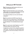
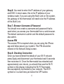
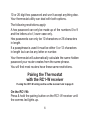
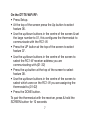
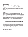
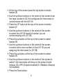
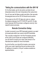
1
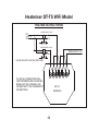
Operating Instructions
Model: DT-TS WiFi RF
01/13 - Version 1.1
Ref: DT-TSWIFI RF
Contents Page
Setting Up Your WiFi Thermostat
Remote Connection Set Up
Display Symbols Explained
Installation Procedure
Temperature Display
Locking the Keypad
Heat On/Off
Clean Screen
Factory Reset
Optional Feature Setup
Wiring Diagrams
1
2-6
10-12
13
16
17
17
18
19
19
20-24
26-28
Setting up your WiFi Thermostat
Step 1: Download and install the network utility from our
web site: www.heatmiser.co.uk/wifi
Step 2: Connect the thermostat to your pc with the USB
cable provided, this will power the thermostat from the USB
port & will allow you to test the Wi-Fi connection.
On the Utility press Read to view the current thermostat
configuration.
Step 3: You should enter the SSID, Security Type and
Security Code of your wireless network. These settings can
be found in your wireless router, consult your router manual
for more information. For more details see security types
below.
Step 4: You need to enter a fixed IP address for your Wi-Fi
Thermostat outside of the router DHCP range.
It is likely that your network will be configured to operate on
a DHCP basis – this means your router automatically issues
an IP address to a device that successfully connects to the
network.
2
Your Wi-Fi thermostat needs a fixed IP address in order for
local and remote access to operate, so you will need to set
this up manually.
Log into your wireless router and navigate to the LAN
settings page. You should see an option for DHCP setup.
This should detail the IP range that can be assigned to
devices connecting to the network.
As an example, you may have an IP starting range
192.168.1.1 and ending 192.168.1.99.
This would mean you can safely provide your Wi-Fi
Thermostat the IP address 192.168.1.100 as no other
devices will be assigned this address by the router.
If your DHCP range is from 192.168.1.1 to 192.168.1.253
you cannot use 254 or above, you will need to change the
DHCP range, taking care not to change any of the first 3
numbers.
Tip! When setting up an IP address, the first three sets of
numbers must be the same as the router IP, the fourth set
must not be used elsewhere on the network.
Step 5: Enter the Subnet mask for the network, this
information can be found in your wireless router.
3
Step 6: You need to enter the IP address of your gateway
and DNS. In most cases, this is the IP address of your
wireless router. If you are using the Multi-Link on the system,
the gateway of the thermostat will need to be the IP address
of the Multi-Link.
Step 7: Browser Username & Password
You should now create a username and password that is
used when you access your thermostat from a web browser.
The default username is admin and the default password is
also admin.
Access PIN
The access PIN is required when you are using the iPhone
app and helps secure your system. This PIN should be
entered in the Network Setup screen.
Step 8: Checking Connection
Once you have entered the details of your Wi-Fi network
press Apply and disconnect your thermostat wait 5 seconds
then reconnect it. Once the thermostat has rebooted wait
approximately one minute, you should then see the Wi-Fi
symbol on the display indicating the Wi-Fi Thermostat
has successfully connected to your network. The Wi-Fi
symbol is 3 curved lines just below the OFF button.
4
Security Types & Compatability Explained
The Wi-Fi Thermostats operate on the 802.11b standard.
If your router is a G model, you should ensure it is setup to
work in B&G mode otherwise you will not be able to connect
to your thermostat.
There are currently 4 methods of securing your wireless
connection in common use
These are :
OPEN/DISABLED (not recommended )
W.E.P.
(lowest security level)
W.P.A.
(medium security )
W.P.A.2.
(highest security )
Your choice of security settings in the thermostat must
match the setting in your router. Quite often you will find
WPA and WPA2 as a single option in the router this is
perfectly normal the router knows which one to use, and
you can therefore set the thermostat up using either one.
The password can be up to 63 characters in length including
spaces _. / \ characters.
The W.E.P. option is not so simple. Some routers generate a
hidden password from a pass phrase whilst others require a
5
10 or 26 digit hex password and won’t accept anything else.
Your thermostat utility can deal with both options.
The following restrictions apply:
A hex password can only be made up of the numbers 0 to 9
and the letters a to f, lower case only.
Hex passwords can only be 10 characters or 26 characters
in length.
If a passphrase is used it must be either 5 or 13 characters
in length but can be any letter or number.
Your thermostat will automatically calculate the same hidden
password your router creates from the same phrase.
You will find most routers have these same restrictions.
Pairing the Thermostat
with the RC1-W receiver
If using the UH1-W wiring centre as the receiver turn to page 8

On the RC1-W:
Press & hold the pairing button on the RC1-W receiver until
the comms led lights up.

6
On the DT-TS WiFi RF:
• Press Setup.
• At the top of the screen press the Up button to select
feature 06.
• Use the up/down buttons in the centre of the screen & set
the large number to 01, this configures the thermostat to
communicate with the RC1-W.
• Press the UP button at the top of the screen to select feature 07.
• Use the up/down buttons in the centre of the screen to
select the RC1-W receiver address you are communicating with.(01-32)
• Press the up button at the top of the screen to select feature 08.
• Use the up/down buttons in the centre of the screen to select which zone on the RC1-W you are assigning the thermostat to.(01-02)
• Press the DONE button.
To pair the thermostat with the receiver, press & hold the
SCREEN button for 10 seconds:
7
Pair Successful
The address of the receiver will flash on the thermostat
display & the comms led will flash on the RC1-W receiver.
Press DONE on the thermostat to confirm pairing with the
RC1-W receiver.
Pair Fail
If the Comms LED on the receiver does not flash, there
could be a problem with the RF signal. Reduce the distance
between the thermostat and receiver, where possible check
that no metal objects are blocking the signal. Also check
that features 06 – 08 have been configured correctly.
Pairing the thermostat with the UH1-W

On the UH1-W:
Set the board id number on the UH1-W by selecting from
01-09 indicated on the rotary switch. Each UH1-W on the
system will need a different id number.

On the DT-TS WiFi RF:
• Press Setup.
8
• At the top of the screen press the Up button to select
feature 06.
• Use the up/down buttons in the centre of the screen & set
the large number to 00, this configures the thermostat to
communicate with the UH1-W.
• Press the UP button at the top of the screen to select
feature 07.
• Use the up/down buttons in the centre of the screen
to select the UH1-W board id number you are
communicating with. (01-09)
• Press the up button at the top of the screen to select
feature 08.
• Use the up/down buttons in the centre of the screen
to select which zone number on the UH1-W you are
assigning the thermostat to. (01-08)
• Press the up button at the top of the screen to select
feature 09.
• Use the up/down buttons in the centre of the screen to
select if the thermostat will bring on the pump & boiler
outputs. 00=UFH (Outputs enabled) 01=Radiator (Outputs
not enabled).
• Press the Done button.

9
Testing the communications with the UH1-W
On the thermostat use the Up button and take the set
temperature above the room temperature then press done.
You will now see the flame symbol and after a few seconds
the assigned zone on the UH1-W should now be active.
If the output on the UH1-W does not come on, reduce
the distance between the DT-TS WiFi RF and UH1-W also
check features 06-09 have been configured correctly, then
repeat the above process.
Remote Connection Setup
In order to connect to your WiFi thermostat remotely, you need
to forward ports within your router to the WiFi thermostat.
This is usually configured in the Port Forwarding section
of the router, as all routers are configured differently,
you will need to consult your router user manual or the
manufacturers website for more information.
As a brief outline, you should first create a new service
within your router, specifying the port number and the
IP address to forward to, the port numbers needed are
explained below.
10
Remote Access via Web Browser
To access your WiFi thermostat remotely via smartphone or
tablet, you need to forward port 8068 to the IP address of
your WiFi thermostat.
Remote access via web browser
To access your WiFi thermostat remotely via web browser,
you need to forward port 80 to the IP address of your WiFi
thermostat.
Connecting to the Thermostat from your
Web Browser
Connecting to the Thermostat from your Web Browser
To connect to your thermostat, open your preferred browser
and enter the IP address that you gave the thermostat during
setup and press enter. You will now be asked for a password
and username, these are both “admin” as default. We
recommend you change these settings to ensure the
security of your system.
For further information, click the help link within the browser.
11
Connecting to the Thermostat from your
Smartphone or Tablet application
To connect to your thermostat, launch the app on your
smartphone or tablet, there are now three sections to fill in.
Lan IP – This is the static IP address you have assigned to
the WiFi thermostat.
WAN IP – This is either your static IP address or Dynamic
DNS address when connecting to your network remotely.
PIN – This is the four digit pin number assigned to the WiFi
thermostat on configuration.
Once this information has been entered the app will store
this for the next time you connect.
12
Wi-Fi Thermostat Display Guide V1.0
V1.0
Shown on the PRT-ETS WiFi Model. Displayed when the floor temperature
rises above the floor limit temperature.
Indicates the current room temperature.
Indicates the current floor temperature (PRT-ETS WiFi Only).
Indicates the thermostat is in Away Mode.
Indicates the thermostat has successfully connected to the Wi-Fi Router.
Indicates the heating output is on.
Indicates the thermostat is locked.
Indicates whether the hot water output is on or off.
Temperature Format Display.
Shown when the thermostat is in “Clean Screen Mode” During this mode,
all buttons are disabled to allow for cleaning of the thermostat.
Shown during a holiday to indicate holiday time remaining.
Shown during a hold period to indicate the hold time remaining.
Wake, Leave, Return, Sleep are the 4 comfort settings available.
Time 1-4 are available only on the PRTHW and TM1 versions.
13
What is a room thermostat?
A room thermostat simply switches the heating system
on and off as necessary. It works by sensing the air
temperature, switching on the heating when the air
temperature falls below the thermostat setting, and
switching it off once this set temperature has been reached.
Turning a room thermostat to a higher setting will not make
the room heat up any faster. How quickly the room heats up
depends on the design of the heating system, for example,
the size of the boiler and radiators.
Neither does the setting affect how quickly the room cools
down. Turning a room thermostat to a lower setting will
result in the room being controlled at a lower temperature,
and saves energy. The heating system will not work if a time
switch or programmer has switched it off.
The way to set and use your room thermostat is to find the
lowest temperature setting that you are comfortable with,
and then leave it alone to do its job. The best way to do this
is to set the room thermostat to a low temperature - say
18ºC - and then turn it up by 1ºC each day until you are
comfortable with the temperature. You won’t have to adjust
14
the thermostat further. Any adjustment above this setting
will waste energy and cost you more money.
If your heating system is a boiler with radiators, there will
usually be only one room thermostat to control the whole
house.
But you can have different temperatures in individual
rooms by installing thermostatic radiator valves (TRVs) on
individual radiators. If you don’t have TRVs, you should
choose a temperature that is reasonable for the whole
house. If you do have TRVs, you can choose a slightly
higher setting to make sure that even the coldest room is
comfortable, then prevent any overheating in other rooms
by adjusting the TRVs.
Room thermostats need a free flow of air to sense the
temperature, so they must not be covered by curtains or
blocked by furniture. Nearby electric fires, televisions, wall
or table lamps may prevent the thermostat from working
properly.
15
Installation Procedure
DO’s
1. Do mount the thermostat at eye level.
2. Do read the instructions fully so that you get the best
from our product.
DON’Ts
1. Do not install near a direct heat source as this will affect
the workings of the thermostat.
2. Do not push hard on the LCD otherwise you will damage
the liquid crystal display and this is not repairable.
Installation
The thermostat is designed to be flush mount, a back
box of 35mm should have been sunk in the wall prior to
installation.
Step 1
Carefully separate the front half of the thermostat from the
back plate by placing a small flat head terminal driver in to
the slots on the bottom face of the thermostat.
16
Step 2
Place the thermostat front half somewhere safe. Terminate
the thermostat as shown in the diagrams at the back of this
booklet.
Screw the thermostat back plate on to the back box
Step 3
Re-connect the two parts of the thermostat.
Temperature Display
Room Temp = This is the current room temperature.
SET = This is the temperature you are trying to achieve in
your home.
Locking the Keypad
The thermostat has a keylock facility. To enable this press
the bottom right corner of the display and hold for 10
seconds
When activated, you will see .
To cancel, repeat the steps above.
17
Temperature Set
Using the
keys allows you to adjust the set
temperature. When you press either of these keys, you
will see the word SET and the desired temperature.
Press Done to accept.
Heat On / Off
Frost Protect Mode: Pressing the Off button once will
place the thermostat in frost protect mode. In this mode,
the thermostat will display the frost icon and will only turn
the heating on should the room temperature drop below the
set frost temperature (see pages 19-23). Should the heating
be turned on whilst in frost mode, the flame symbol will be
displayed. To cancel the frost protect mode, press the On
button.
Thermostat Off: To turn the thermostat off completely,
press and hold the Off button. The display and heating
output will be turned off. To turn the thermostat back on,
press the On button.
18
Clean Screen
Pressing Clean Screen will disable all buttons, allowing you
15 seconds to wipe the screen clean.
Factory Reset
The thermostat has a factory reset function. This will reset
all settings back to their factory default.
To perform a factory reset, follow these steps:
Turn off the thermostat by pressing and holding the off
button. Press and hold the bottom left corner of the LCD for
10 seconds. You will see all the icons appear for 2 seconds
and then disappear. You now need to power down the
thermostat for 5 seconds and then power on again.
19
THE FOLLOWING SETTINGS ARE OPTIONAL AND
IN MOST CASES NEED NOT BE ADJUSTED
Optional Features Explained
Feature 01 – Temperature Format: This function allows
you to select between °C or °F.
Feature 02 - Switching Differential: This function allows
you to increase the switching differential of the thermostat.
The default is 1°C which means the thermostat will switch
the heating on 1°C below the set temperature and will turn
it off when the set temperature is achieved. With a 2°C
differential, the heating will switch on 2°C below the set
temperature and will switch off when the set temperature is
achieved.
Feature 03 - Frost Protect: You can set whether the
thermostat will maintain the frost temperature when the
thermostat display is turned off. As a default, this is enabled.
Feature 04 – Frost Protect Temperature: This is the
temperature maintained when the thermostat is in frost
mode. The range is 07-17°C. The default is 12°C and is
suitable for almost all applications.
20
Feature 05 – Output Delay: To prevent rapid switching, an
output delay can be entered. This can be set from 00-15
minutes. The default is 00 which means there is no delay.
Feature 06 – UH1-W or RC1-W Receiver: The thermostat
can work with our UH1-W or RC1-W. This setting
determines which is being used. 00 = UH1-W, 01 = RC1-W
Feature 07 – Receiver Address: Within one building, up
to 9 UH1-W’s or 32 RC1-W receivers can be used. Each
receiver must have a unique receiver address.
Feature 08 – Zone Number: This is the zone number you
are assigning the thermostat to on either the UH1-W or the
RC1-W receiver. 01-08 - UH1-W, 01-02 – RC1-W
Feature 09 – Underfloor Heating or Radiator Zone
(UH1-W Only): This setting determines whether the
thermostat will activate the pump & boiler output on the
UH1-W. If set to 00 the outputs will be activated.
00 = UFH, 01 = Radiators
Feature 10 – Fail Safe: If enabled, the thermostat will
send a signal to the receiver every 20 minutes. Should the
receiver fail to receive two signals, the receiver will activate
21
the output for 20% of the time. This is to protect the system
against a loss of wireless signal or should the thermostat
battery fail whilst you are away.
Feature 11 – Temperature Up/Down Limit: This function
allows you to limit the use of the up and down temperature
arrow keys. This limit is also applicable when the thermostat
is locked and so allows you to give others limited control
over the heating system.
Feature 12 – Sensor Selection: On this thermostat you can
select to use the built in sensor (00) or remote air sensor
(01).
Adjusting the Optional Settings
To adjust the settings, follow these steps:
• With the thermostat turned on.
• Press SETUP.
• Use the
at the top of the screen to select the
feature number (shown on pages 22-23) and then use
the
keys in the centre adjust the setting.
• Press Done to accept and Store.
22
Feature Table
Feature
Description
Setting
01
Temperature Format
00=°C 01=°F
Switching
Differential
0.5=0.5°C - 3.0=3°C
1.0°C = Default
02
03
Frost Protect
04
00 = Disabled 01=Enabled
(01=Default)
Frost Temp
07-17°C
(12=Default)
05
Output Delay
Enter value
00-15 minutes (00=Default)
06
Receiver Type
00 = UH1-W
01 = RC1-W
07
Receiver Address
UH1-W = 01-09
RC1-W = 01-32
08
Zone Number
UH1-W = 01-08
RC1-W = 01-02

23
Feature Table (continued)
Feature
Description
Setting
09
Under-floor Heating
or Radiators
(UH1-W Only)
00 = UFH
01 = Radiators
10
Fail Safe
00 = Disabled
01 = Enabled
11
Temp Limit
00 – 10°C
12
Sensor Selection
24
00 = Built In Sensor
01 = Remote Air Sensor
Re-calibrating the thermostat
If you need to re-calibrate the thermostat follow these
instructions:
1. Press and hold the OFF button to turn the thermostat off.
2. Press and hold the ON button until the temperature
appears on the screen.
3. Use the up/down buttons to set the new temperature.
4. Press DONE to accept.
5. Press the ON button once to turn the thermostat back on.
25
Heatmiser DT-TS WiFi Model
NOTE This model is designed to work with the
RC1-W and the UH1-W please refer to the
appropriate diagram for connections to your
heating system.
REMOTE AIR PROBE
IF FITTED
MAINS SUPPLY
FROM FUSED
SPUR
N L
RT2 -
N L
REMOTE AIR SENSOR
Wi-Fi THERMOSTAT
Name DT-TS WIFI RF
Date 15/02/2012 Rev 002
MAX CABLE SIZE 1.5mm
BACK BOX DEPTH 35MM
Drawn by Alan Mee
26
Heatmiser DT-TS WiFi Model
COMBINATION BOILER SYSTEM
TO BOILER
P/L
S/L
S/L = SWITCHED LIVE
P/L = PERMANENT LIVE
MAINS SUPPLY
A1
A2
B2
B1
N
L
RC1-W
RECEIVER
S/L AND P/L CONNECTIONS WILL VARY DEPENDING ON THE
BOILER MODEL , BUT WOULD NORMALLY BE CONNECTED
TO THE THERMOSTAT CONNECTIONS
27
Heatmiser DT-TS WiFi Model
TWO ZONE HEATING SYSTEM
P/L
TO BOILER
HEATING ZONE 1 VALVE
L
N
S/L
NEUTRAL
HEATING ZONE 2 VALVE
L
N
MAINS SUPPLY IN
NEUTRAL
N.B VALVES MUST HAVE END SWITCHES
P/L AND S/L CONNECTIONS WILL
VARY DEPENDING ON THE BOILER
MODEL BUT WILL NORMALLY BE
CONNECTED TO THE THERMOSTAT
CONNECTIONS
B2
B1 A2 A1
RC1-W
RECEIVER
28
N
L