1
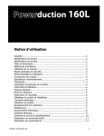
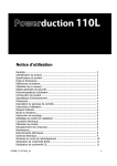
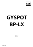
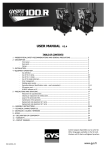
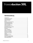
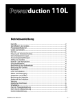
User manual
Warranty ................................................................................................... 2
Identification of the machine ...................................................................... 2
Product specifications ................................................................................. 2
Dimensions and weight............................................................................... 2
Normative references ................................................................................. 2
Using this manual....................................................................................... 3
General notes on safety .............................................................................. 3
Recommendations of use ............................................................................ 3
Constructions features ................................................................................ 4
Signs and warning signs ............................................................................. 4
List of protections....................................................................................... 4
Control panel description ............................................................................ 5
Instructions of use ..................................................................................... 6
Residual risks ............................................................................................. 6
Noise and vibrations ................................................................................... 6
Demolition and disposal .............................................................................. 6
Unpacking and installation .......................................................................... 6
Electrical connection ................................................................................... 6
Using the machine...................................................................................... 6
Replacing the inductor ................................................................................ 6
Maintenance .............................................................................................. 7
Electrical connections ................................................................................. 8
Electrical diagrams ..................................................................................... 9
Cooling liquid circuit diagrams ..................................................................... 10
RoHS declaration of compliance .................................................................. 11
CE declaration of conformity ....................................................................... 11
053410_01 01 2015_V1.1
-1-
WARRANTY
Upon delivery, the buyer will have to make sure that the machine is complete of all parties. Deficiencies and
anomalies must be reported within the terms of the law. Any attempt to tamper with any part of the machine
and / or any plaque on the machine itself, invalidate the warranty, CE marking (if affixed by the manufacturer),
the declaration of conformity and / or the manufacturer's declaration.
The manufacturer is also considered exempt from liability arising from the following cases:
- Incorrect installation;
- Improper use of the machine by personnel not adequately trained;
- Improper use of the relevant safety regulations;
- Lack of maintenance;
- Modification of the machine or use of non-original parts for the repair.
IDENTIFICATION OF THE MACHINE
On the back of the machine appears an identification plate, on which in addition to CE marking is reported :
• Name and address of the manufacturer
• Year of manufacture
• Model
• Type of machine
• Weight
• Voltage
These data must be mentioned whenever it requires the intervention of technicians or for the request of spare
parts.
PRODUCT SPECIFICATIONS
Induction heater.
Power: 5.2 kW
Voltage: 220 V
Mains frequency : 50 Hz
Heater frequency : 20-40 kHz, controlled by a microprocessor
Insulation: Class F, No. of poles: 2 + T
Cooling liquid : provided. Standard automotive cooling liquid (water + 30% max. glycol).
Mains cable : 8 m.
Inductor cable : 3 m.
DIMENSIONS AND WEIGHT
Weight 65 kg, height 900 mm + 96 mm wheels
Width 520 mm
Depth 420 mm
NORMATIVE REFERENCES
Directive CE2004/40 / Exposure to electromagnetic fields
The Low Voltage Directive CE 2006/95
Machinery Directive 2006/42/EC
EMC Directive 2004/108/EC
Directive 2002/95/EC
EC Directive 2002/96
053410_01 01 2015_V1.1
-2-
USING THIS MANUAL
It is very important that this manual, designed to provide the user with a general knowledge of the machine, as
well as instructions for use and maintenance deemed necessary for the proper operation, be kept with the
machine for future reference.
The user manual, as mentioned by the law, is an integral part of the machine and must accompany it until its
destruction.
The warnings given must be read carefully, for safety reasons, before installation and use. It is prohibited for
any reason to modify this manual without the written permission of the manufacturer or dealer.
GENERAL NOTES ON SAFETY
The machine is constructed in a workmanlike manner. Its durability and reliability will be much more effective if
it is correctly used and regular maintenance is done.
Always read the instructions contained in this manual, they provide important information for safety.
RECOMMENDATIONS OF USE
This machine should be used only for the purpose for which it has been designed, namely: generate heat within
ferrous materials. Any other use not expressly provided in this manual is strictly forbidden, as improper and
therefore dangerous. The machine is semi-automatic and requires the presence of the operator.
WARNINGS :
The following recommendations should be strictly followed by users, in order to
prevent risks of material damage, or people injuries.
The operator has the personal responsibility to respect, not only for himself, but also those who may be exposed
to the risks of the machine, all the rules that relate to security. Before performing any operation with the
machine, therefore, carefully read this manual, as it gives guidelines and procedures to operate the product
correctly and safety.
• The use of the machine must be carried out only by trained adult personnel and in full compliance with local
regulations and the instructions contained in the manual.
• Strictly follow the signs and mandatory signs and hazard on the machine.
• Before any maintenance electrically isolate the machine to prevent accidental starting.
• In the event of injury or breakage of connecting pipes or electrical cables, act promptly to replace them.
• In case of leakage of cooling liquid, the floor must be cleaned to avoid risks of people falling.
• Do not leave the equipment exposed to the weather (rain, wind, etc…).
• Do not leave the equipment unattended in the hands of children.
• Should you decide not to use the equipment, you will make it inoperative fulfilling to all practices relating to
disposal in accordance with law.
053410_01 01 2015_V1.1
-3-
CONSTRUCTIONS FEATURES
The machine was designed and built in compliance with the essential health and safety requirements laid down
by the Machinery Directive 89/392 EEC and subsequent amendments.
In particular, given that the operator is in direct contact with the machine :
• Eliminate sharp edges and sharp angles;
• Avoid unstable conditions that can result in a risk of overturning, falling or inappropriate movements;
• Ensure that the operator cannot come into direct contact with live parts during machining which may cause
electric shock or injury.
And everything else needed to secure its use.
The main parts of
POWERDUCTION
can
summarized as follows:
1)
2)
3)
4)
5)
6)
the
be
ON/FF switch
Control panel
Inductor
PCB
Fan
Cooling unit
Signs and warning signs
On the machine are placed signal warnings and mandatory signs that the operator must follow for his personal
safety and security.
Protections
The machine is safe to use, however the utmost attention is recommended
during use, as heated materials can burn on contact for a long time after the
passing of the inductor. The inductor itself, even if continuously cooled, may
become warm to the touch on parts red-hot and therefore there is a risk of
burns.
The machine is equipped with several electronic protection systems against
electrical surges and overheating. The thermal protection of the inductor
mainly occurs when heating parts in metallic alloys. To start the product
again, release and press again the button. For all the other protections,
switch off the product using the ON/OFF switch.
Finally there are 2x 32 A fuses on the heating circuitry (fuse holder under the metallic cover of the product).
053410_01 01 2015_V1.1
-4-
The fuses should only be replaced after the defect has been eliminated.
053410_01 01 2015_V1.1
-5-
CONTROL PANEL DESCRIPTION
1
General ON/OFF switch
2
Power setting buttons
3
Power indicator (1kW – 5 kW).
4
Induction heating activation
5
Alarm indicator – Cooling circuit
6
7
Heating indicator (ON=heating; blinking = stand-by).
Heat switch
8
Inductor (ferrite)
9
Cooling liquid temperature alarm (machine stopped)
10
Inductor alarm (wrong inductor or short-circuit)
« Alarm » indicators :
The alarm indicators above mean, from left to right :
1. A cooling liquid temperature which is too high. Leave the product ON without using the inductor, in order for
the cooling liquid temperature to decrease.
2. An issue with the flow of cooling liquid (pump issue, blocked pipe).
3. A defective inductor; contact JBDC after sales or your local distributor.
Note : in case of alarm, the product does not heat up.
053410_01 01 2015_V1.1
-6-
INSTRUCTIONS OF USE
The product is delivered with a single phase 220V / 50 Hz plug. In order to ensure an optimum use, the product
should be connected to an electrical installation with minimum protection 25A (ideally 32A), and protected
according to applicable standards. See the instructions for electrical connections on page 20.
Turn the ON/OFF switch to the ON position. Press the induction heating activation button (4) described on page
5. The light on button 6 blinks indicating that the product is ready to heat. Position the inductor (8) flat on the
part or the area to heat up, placing the open part of the ferrite against the part. Press the red button (7) on the
handle of the inductor to start heating; if necessary move the inductor in order to heat up a larger surface on
the part. After stopping the heating, decrease the heating power level on the control panel, and secondly only
switch off the product; this way the cooling circuit will reduce the temperature of the inductor before switching
off completely the product.
RESIDUAL RISKS
WARNING!
The machine has been designed to ensure maximum safety. The possibility exists that the operator may get
burnt if he touches hot parts.
WARNING!
The machine must not be used near sensitive materials or dangerous explosives, compressed gases, flammable
liquids, electrical equipment.
Metal objects may not be worn in the vicinity of the inductor, as they will become hot (rings on finger for
example).
It is forbidden for people wearing pace-makers or any other biomedical equipment to use this product.
Noise and vibrations
The machine produces a sound pressure level for continuous use of less than 60dB (A).
The machine does not generate significant vibrations that may cause danger.
Demolition and disposal
Some materials, with which the machine is built, can be recycled, therefore the recycling of the product should
be performed in accordance with relevant local regulations.
Unpacking and installation
The machine is supplied ready for use. Before operating, you must remove all packing material and place the
product carefully in a suitable place (ground even, dry and ventilated place).
WARNING!
The installation must be designed to allow easy access to all its parts. A minimum space around the product
must be guaranteed for good operation and maintenance, without problems and risks for the operator.
Replacing the inductor
WARNING!
The replacement of the inductor should be performed only by authorized staff and only after removing power to
the machine.
WARNING!
During maintenance and / or repair, wear protective gloves. Electrically isolate the machine by disconnecting it
from the mains.
WARNING!
It is forbidden to start using the machine if all the metallic covers have not been screwed back on the product
and if all the safety devices are not operational.
053410_01 01 2015_V1.1
-7-
WARNING!
This machine has been designed to reduce at the maximum the risks relative to exposure to electromagnetic
fields. However, residual risks may remain, and therefore it is recommended to respect a minimum safety
distance of 30cm between the inductor and the head or the chest of the operator.
MAINTENANCE
General recommendations
• It is essential that the maintenance of the machine be carried out by qualified and authorized personnel,
which is aware of the mode of operation thereof.
• Never perform any cleaning, lubrication or maintenance with the machine running.
• Before any maintenance work, switch to "0" the main power switch to turn off the power, unplug it from the
network to avoid electrical shock or other hazards resulting from mishandling.
• Do not wear rings, watches, jewellery, dangling clothing, such as ties, torn garments, scarves, unbuttoned
jackets or zip open that can be caught at work.
• Instead, you should use suitable clothes for accident prevention, for example: non-slip shoes, anti-noise
headphones, goggles, appropriate gloves, etc. ...
• Never use gasoline or flammable solvents to clean the machine. Use water and, if needed, commercial nontoxic solvents.
• After the interventions, always refit, before restarting the machine, the guards eventually removed.
Preventive Maintenance
Meticulous inspections carried out at regular intervals of time are necessary in order to detect and eliminate
faults quickly, before they can cause damage.
WARNING !
Every time you need to use the IMS POWERDUCTION 50L product, check first the safety devices of
the product, and any anomaly which could lead to bad operation of the product. Check daily for
wear and legibility of the warning signs.
WARNING !
The operational safety of the machine can only be guaranteed if repairs are carried out using only the original
spare parts and if approved maintenance instructions are carried out correctly.
After each use, with the electrical system turned off, the machine should be cleaned promptly, to remove dust
or dirt in general, because they may decrease ventilation and alter the proper functioning of the product and its
durability.
Before each use, check the operation of the control devices, safety devices and the integrity of the electrical
connection cables.
WARNING !
Make periodic visual checks on the inductor to verify that there are no fluid leaks and air inlet port to verify that
they are free.
053410_01 01 2015_V1.1
-8-
ELECTRICAL CONNECTIONS
The product has been designed for 220V / 50 Hz single phase electrical supply.
WARNING : do not use on 60Hz electrical supply.
Single-phase 220V electrical supply :
P1 - 220V
IMS POWERDUCTION
50L
N
Terre/ Earth
3-phase electrical supply :
P3
P2
P1 – 220V
IMS POWERDUCTION
50L
N
Terre/ Earth
053410_01 01 2015_V1.1
-9-
ELECTRICAL DIAGRAMS
Wiring diagram
1) Inductor switch 1209000420
2) Thermostat 1309000406
3) Flow meter 1109000413
4) Main switch
5) Fuse 32 A 1109000211
6) Front panel keypad 1209000203
7) Electronic board 1209000202
8) Fan 1209000205
9) Coupling capacitor 1209000206
10) Isolation transformer 209000207
11) Resonance capacitor 1209000208
12) Torch / junction box 1209000201
13) Inductor 1209000210
14) Flux concentrator 1209000219
053410_01 01 2015_V1.1
- 10 -
COOLING LIQUID CIRCUIT DIAGRAMS
1)
2)
3)
4)
5)
6)
7)
Fan 1209000304
Radiator 1209000305
Thermostat 1309000406
1209000201 junction box with heating head
Flow 1109000413
Pump 1209000303
Tank 1209000302
Components and parts
This section contains a list of the components of this machine. Its contents may be used for identification of
spare parts. For rapid delivery of spare parts, please quote the following order:
1)
2)
3)
4)
5)
6)
Number in the list
Code number (design or commercial)
Name of part
Quantity
Serial number of the machine
Year of manufacture
053410_01 01 2015_V1.1
- 11 -
ROHS CERTIFICATE OF COMPLIANCE
Directive 2002/95/EC of the European Parliament and of the Council of 27 January 2003 on the
restriction of use of certain hazardous substances in electrical and electronic equipment
JBDC declares that:
The IMS POWERDUCTION 50L product complies with this directive and does not contain concentrations that
exceed the limits for the following substances :
-
Lead (Pb)
Mercury (Hg)
Cadmium (Cd)
Hexavalent chromium (Cr (VI))
Polybrominated biphenyls (PBB)
Polybrominated diphenyl ethers (PBDEs)
CE DECLARATION OF CONFORMITY
JBDC certifies that the product IMS POWERDUCTION 50L is compliant with the following directives and
standards :
Directive CE2004/40 / Exposure to electromagnetic fields.
The Low Voltage Directive CE 2006/95.
Machinery Directive 2006/42/EC.
EMC Directive 204/108 EEC.
Directive 200 2/95/CE.
EC Directive 2002/96.
Changes which would have effects on the technical specifications of the product and affect the use in conformity
with the user manual, make this declaration of conformity not valid!
01/01/2015
JBDC
134 BD des Loges
53941 Saint Berthevin
053410_01 01 2015_V1.1
Nicolas BOUYGUES
Président Directeur Général/ CEO
- 12 -