1
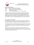
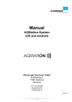
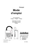
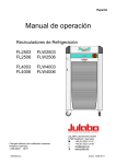
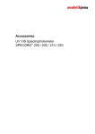
English Operating manual Immersion Coolers FT402 FT902 °C FT902 JULABO GmbH 77960 Seelbach / Germany Tel. +49 (0) 7823 / 51-0 Fax +49 (0) 7823 / 24 91 [email protected] www.julabo.de FT 402 1.951.4620-V2 19514620-V2.doc °C 06/13 26.07.13 Congratulations! You have made an excellent choice. JULABO thanks you for the trust you have placed in us. This operating manual has been designed to help you gain an understanding of the operation and possible applications of our immersion coolers. For optimal utilization of all functions, we recommend that you thoroughly study this manual prior to beginning operation. The JULABO Quality Management System Temperature control devices for research and industry are developed, produced, and distributed according to the requirements of ISO 9001 and ISO 14001. Certificate Registration No. 01 100044846 Unpacking and inspecting Unpack the immersion cooler and accessories and inspect them for possible transport damage. Damage should be reported to the responsible carrier, railway, or postal authority, and a damage report should be requested. These instructions must be followed fully for us to guarantee our full support of your claim for protecting against loss from concealed damage. The form required for filing such a claim will be provided by the carrier. Printed in Germany Changes without prior notification reserved Important: keep operating manual for future use 2 Immersion Coolers TABLE OF CONTENTS Operating manual .................................................................................................................... 4 1. Intended use ................................................................................................................... 4 1.1. Description .................................................................................................................. 4 2. Operator responsibility – Safety instructions ................................................................... 4 2.1. Disposal ...................................................................................................................... 6 2.2. EC Conformity ............................................................................................................ 7 2.3. Warranty conditions .................................................................................................... 7 2.4. Technical specifications .............................................................................................. 8 Operating instructions ........................................................................................................... 11 3. Operating controls and functional elements .................................................................. 11 4. Safety notes for the user ............................................................................................... 13 4.1. Explanation of safety notes ....................................................................................... 13 4.2. Explanation of other notes ........................................................................................ 13 4.3. Safety instructions .................................................................................................... 14 5. Preparations.................................................................................................................. 15 5.1. Installation................................................................................................................. 15 5.2. Immersion probe / Sensor connection - Pt100 .......................................................... 15 6. Operating procedures ................................................................................................... 17 6.1. Power connection ..................................................................................................... 17 6.2. Switching on / Start - Stop ........................................................................................ 17 6.3. Automatic / non-automatic start mode ...................................................................... 18 6.4. Setting the temperatures........................................................................................... 19 6.5. Temperature control.................................................................................................. 19 7. Troubleshooting guide / Error messages ...................................................................... 20 8. Electrical connection ..................................................................................................... 21 9. Cleaning / repairing the unit .......................................................................................... 22 3 Operating manual Operating manual 1. Intended use JULABO immersion coolers have been designed for temperature application to specific fluids in a bath tank. For example: Dewar vessels, beakers, or other containers in conjunction with heating circulators for continuous countercooling or for dry-ice substitution. JULABO immersion coolers are not suitable for direct temperature control of foods, semi-luxury foods and tobacco, or pharmaceutical and medical products. Direct temperature control means unprotected contact of the object with the bath medium (bath fluid). 1.1. Description The immersion coolers are operated via the keypad. The implemented microprocessor technology allows to set and to store the setpoint that can be indicated on the LED temperature display. The PID temperature control adapts the cooling supply to the thermal requirements of the bath. Electrical connection: PID1 Pt100 Connection for Pt100 external sensor for temperature measurement and control. Model FT402 is provided with a handle for portable use. Model FT902 is equipped with four castors. Two of the castors include locking levers that should be pressed down after setting up the unit to prevent it from moving. The immersion probe is connected to the instrument with a flexible, specially insulated tube. On model FT902 the immersion probe is also flexible and may be adjusted precisely to different positions within the vessel. 2. Operator responsibility – Safety instructions The products of JULABO ensure safe operation when installed, operated, and maintained according to common safety regulations. This section explains the potential dangers that may arise when operating the circulator and also specifies the most important safety precautions to preclude these dangers as far as possible. The operator is responsible for the qualification of the personnel operating the units. The personnel operating the units should be regularly instructed about the dangers involved with their job activities as well as measures to avert these dangers. Make sure all persons tasked with operating, installing, and maintaining the unit have read and understand the safety information and operating instructions. 4 Immersion Coolers When using hazardous materials or materials that could become hazardous, the circulator may be operated only by persons who are absolutely familiar with these materials and the circulator. These persons must be fully aware of possible risks. If you have any questions concerning the operation of your unit or the information in this manual, please contact us! Contact JULABO GmbH Eisenbahnstraße 45 77960 Seelbach / Germany +49 (0) 7823 / 51-0 +49 (0) 7823 / 24 91 [email protected] www.julabo.de Safety instructions for the operator: Avoid strikes to the housing, vibrations, damage to the operating-element panel (keypad, display), and contamination. Make sure the product is checked for proper condition regularly (depending on the conditions of use). Regularly check (at least every 2 years) the proper condition of the mandatory, warning, prohibition and safety labels. Make sure that the mains power supply has low impedance to avoid any negative effects on the instruments being operated on the same mains. This unit is designed for operation in a controlled electromagnetic environment. This means that transmitting devices (e.g., cellular phones) should not be used in the immediate vicinity. Magnetic radiation may affect other devices with components sensitive to magnetic fields (e.g., monitors). We recommend maintaining a minimum distance of 1 m. Permissible ambient temperature: max. 40 °C, min. 5 °C. Permissible relative humidity: 50% (40 °C). Do not store the unit in an aggressive atmosphere. Protect the unit from contamination. Do not expose the unit to sunlight. Appropriate operation Only qualified personnel is authorized to configure, install, maintain, or repair the circulator. Persons who operate the circulator must be trained in the particular tasks by qualified personnel. The summarized user guidance (short manual) and the specification table with information on individual parameters are sufficient for this. Use The bath can be filled with flammable materials. Fire hazard! There might be chemical dangers depending on the bath medium used. Observe all warnings for the used materials (bath fluids) and the respective instructions (safety data sheets). Insufficient ventilation may result in the formation of explosive mixtures. Only use the unit in well ventilated areas. Only use recommended materials (bath fluids). Only use non-acid and non corroding materials. 5 Operator responsibility – Safety instructions When using hazardous materials or materials that could become hazardous, the operator must affix the enclosed safety labels (1 + 2) to the front of the unit so they are highly visible: 1 Warning label W00: Colors: yellow, black Danger area. Attention! Observe instructions. (operating manual, safety data sheet) 2 Mandatory label M018: Colors: blue, white Carefully read the user information prior to beginning operation. Scope: EU or Semi S1-0701 Table A1-2 #9 Carefully read the user information prior to beginning operation. Scope: USA, NAFTA 2 Particular care and attention is necessary because of the wide operating range. There are thermal dangers: Touchable parts of the probe can be very cold. The user must attach the enclosed safety labels to the unit so they are easily visible. Safety label including warning label W017: Colors: yellow, black Attention: Do not touch cold probe. -40 °C / -90 °C 2.1. Disposal The product may be used with oil as bath fluid. These oils fully or partially consist of mineral oil or synthetic oil. For disposal, follow the instructions in the material safety data sheets. This unit contains the refrigerants R134a R404A, and R-23, which at this time are not considered harmful to the ozone layer. However, over the long operating period of the unit, disposal rules may change. Therefore, only qualified personnel should handle the disposal. Valid in EU countries See the current official journal of the European Union – WEEE directive. Directive of the European Parliament and of the Council on waste electrical and electronic equipment (WEEE). This directive requires electrical and electronic equipment marked with a crossed-out trash can to be disposed of separately in an environmentally friendly manner. Contact an authorized waste management company in your country. Disposal with household waste (unsorted waste) or similar collections of municipal waste is not permitted! 6 Immersion Coolers 2.2. EC Conformity The products described in the operating instructions conform to the requirements of the following European guidelines: Directive of the European Parliament and of the Council on the approximation of the laws of the Member States relating to machinery. Low voltage regulations with respect to legal harmonization of the member countries concerning electric devices for use within certain voltage limits. EMC guideline with respect to legal harmonization of the member countries concerning electromagnetic compatibility. JULABO GmbH Eisenbahnstr. 45 77960 Seelbach / Germany 2.3. Warranty conditions JULABO GmbH warrants its products against defects in material or in workmanship, when used under appropriate conditions and in accordance with appropriate operating instructions for a period of ONE YEAR. Extension of the warranty period – free of charge With the ‘1PLUS warranty’ the user receives a free of charge extension to the warranty of up to 24 months, limited to a maximum of 10 000 working hours. To apply for this extended warranty the user must register the unit on the JULABO web site www.julabo.de, indicating the serial no. The extended warranty will apply from the date of JULABO GmbH’s original invoice. JULABO GmbH reserves the right to decide the validity of any warranty claim. In case of faults arising either due to faulty materials or workmanship, parts will be repaired or replaced free of charge, or a new replacement unit will be supplied. Any other compensation claims are excluded from this guarantee. 7 Operator responsibility – Safety instructions 2.4. Technical specifications Immersion cooler FT402 Working temperature range °C -40 ... 30 Temperature stability °C ±0.5 Temperature selection digital Temperature indication LED Resolution °C Temperature control 0.1 PID1 Cooling capacity °C +20 10 Medium ethanol kW 0.45 0.36 0.14 0.03 Cooling compressor 1-stage Refrigerant R404A R134a 230 V / 50 Hz 115 V / 60 Hz -20 -40 Electrical connections: Pt100 external sensor Pt100 Overall dimensions (WxDxH) cm 20x30x43 Immersion probe (Lxdia.) cm 12x5 Immersion probe, flexible (Lxdia.) cm ------- Connection tubing (L) cm 120 Noise level, distance 1 m dBA 61 Weight kg 24 Ambient temperature °C 5 ... 35 V/ Hz 207-253 / 50 A 4 V/ Hz 90-127 / 60 A 4 Mains power connection Current input Mains power connection Current input 230 V/50 Hz (at 230 V) 115 V/60 Hz (at 115 V) All measurements have been carried out at: rated voltage and frequency ambient temperature: 20 °C Technical changes without prior notification reserved. 8 Immersion Coolers Immersion cooler FT902 Working temperature range °C -90 ... 30 Temperature stability °C ±1 Temperature selection digital Temperature indication LED Resolution °C Temperature control 0.1 PID1 Cooling capacity °C +20 10 -20 -40 -80 Medium ethanol kW 0.27 0.27 0.24 0.2 0.07 Cooling compressor 2-stage Refrigerant R404A/R23 R404A/R23 230 V / 50 Hz 115 V / 60 Hz Electrical connections: Pt100 external sensor Pt100 Overall dimensions (WxDxH) cm 38x55x60 Immersion probe (Lxdia.) cm ------- Immersion probe, flexible (Lxdia.) cm 65x1.5 Connection tubing (L) cm 160 Noise level, distance 1 m dBA 60 Weight kg 50 Ambient temperature °C 5 ... 35 V/ Hz 207-253 / 50-60 A 5 V/ Hz 90-127 / 60 A 7 Mains power connection Current input Mains power connection Current input 230 V/50-60 Hz (at 230 V) 115 V/60 Hz (at 115 V) All measurements have been carried out at: rated voltage and frequency ambient temperature: 20 °C Technical changes without prior notification reserved. 9 Operator responsibility – Safety instructions Safety installations according to IEC 61010-2-010: Alarm message optical + audible (permanent) Environmental conditions according to IEC 61 010-1: Use indoors only. Altitude up to 2000 m - normal zero. Ambient temperature: see Technical specifications Humidity: Max. relative humidity 80% for temperatures up to +31 °C, linear decrease down to 50% relative humidity at a temperature of +40 °C Max. mains voltage fluctuations of ±10% are permissible. Protection class according to IEC 60 529 The unit corresponds to Class I Overvoltage category Pollution degree IP21 II 2 Caution: The unit is not for use in explosive environment. EMC requirements according to EN 61326-1 This unit is an ISM device classified in Group 1 (using high frequency for internal purposes), Class A (industrial and commercial range). 10 Immersion Coolers Operating instructions 3. Operating controls and functional elements FT402 Front view Rear view 13 °C 1-7 8 12 10 A M P 10 A M P 9 11 10 FT 402 1 Mains power switch, illuminated I on 2 off Edit keys (increase/decrease setting) 3 Enter key (store) 4 LED temperature display 5 Control indicator –Heating (without function) 6 Control indicator – Cooling 7 Control indicator – Alarm 11 Operating controls and functional elements FT902 Front view Rear view 13 1-7 FT902 °C 8 16 A M P 16 A M P 12 9 11 10 14 15 15 8 Pt100 External Pt100 sensor connector Included with each unit: Order No. 8 981 003 Pt100 sensor, 200x6 mm dia., stainless steel 9 Clamp for immersion probe 10 Immersion probe 11 Mains power cable with plug 12 15 A M P Mains circuit breakers (resettable) FT402 10 A FT902 15 A 13 Carrying handle 14 Venting grid, removable (only FT902) 15 Castor with brake (at the front) Castor without brake (at the back) 12 Immersion Coolers 4. 4.1. Safety notes for the user Explanation of safety notes In addition to the safety warnings listed above, warnings are posted throughout the manual. These warnings are designated by an exclamation mark inside an equilateral triangle. “Warning of a dangerous situation (Attention! Please follow the documentation).” The danger is classified using a signal word. Read and follow these important instructions. Warning: Describes a possibly highly dangerous situation. If these instructions are not followed, serious injury and danger to life could result. Caution: Describes a possibly dangerous situation. If this is not avoided, slight or minor injuries could result. A warning of possible property damage may also be contained in the text. Notice: Describes a possibly harmful situation. If this is not avoided, the product or anything in its surroundings can be damaged. 4.2. Explanation of other notes Note! Draws attention to something special. Important! Indicates usage tips and other useful information. 13 Safety notes for the user 4.3. Safety instructions Follow the safety instructions to avoid personal injury and property damage. Also, the valid safety instructions for workplaces must be followed. 14 Only connect the unit to a power socket with an earthing contact (PE – protective earth)! The power supply plug serves as a safe disconnecting device from the line and must always be easily accessible. Place the unit on an even surface on a base made of nonflammable material. Do not stay in the area below the unit. Make sure you read and understand all instructions and safety precautions listed in this manual before installing or operating your unit. Do not touch the immersion probe if it is frosted. Do not bend the tube connection of the immersion probe Keep the air intake and exhaust grids free of obstructions. (Maintain a sufficient distance from all surrounding surfaces!) Do not move the unit from the position where it was set up during operation. Always turn off the unit and disconnect the mains cable from the power source before performing any service or maintenance procedures, or before moving the unit. Always turn off the unit and disconnect the mains cable from the power source before cleaning the unit. Transport the unit with care. Sudden jolts or drops may cause damage in the interior of the unit. Observe all warning labels. Never remove warning labels. Never operate units with damaged mains power cables. Repairs are to be carried out only by qualified service personnel. There are thermal dangers: Touchable parts of the probe can be very cold. Therefore, exercise particular caution when touching these parts. Use gloves. Immersion Coolers 5. 5.1. Preparations Installation 5.2. Place the unit on an even surface on a pad made of non-flammable material. The place of installation should be large enough and provide sufficient air ventilation to ensure the room does not warm up excessively because of the heat the instrument rejects to the environment. (Max. permissible ambient temperature: 35 °C). For a fault (leakage) in the refrigeration system, the standard EN 378 prescribes a certain room space to be available for each kg of refrigerant. > For 0.25 kg of refrigerant R134a, 1 m3 of space is required. > For 0.52 kg of refrigerant R404A, 1 m3 of space is required. > For 0.68 kg of refrigerant R23, 1 m3 of space is required. The instrument should be set up at a frost-proof and dry location. The ambient temperature must not exceed 35 °C. Press down the castor levers on model FT902. Keep at least 20 cm of open space on the front and rear venting grids. Do not set up the unit in the immediate vicinity of heat sources and do not expose to sun light. Before operating the unit after transport, wait about one hour after setting it up. This will allow any oil that has accumulated laterally during transport to flow back down thus ensuring maximum cooling performance of the compressor. Immersion probe / Sensor connection - Pt100 Caution: Avoid touching the immersion probe if it is frosted. DANGER OF INJURY. Use gloves. -40 °C / -90 °C Switch the unit on only if the probe is immersed into the bath fluid. 15 Preparations The immersion coolers are provided with a Pt100 sensor 200x6 mm dia., stainless steel - Order No. 8 981 003 Pt100 Connect the Pt100 sensor to the connector (Pt100) . To prevent the immersion probe (A) from icing, it should be completely immersed into the bath liquid (B). FT902 S FT402 A S B 120 mm minimum Important: Place the external sensor (S) into the bath medium and securely fix the sensor. FT902: The diameter of the bent probe should not be less than 120 mm. Accessories: 16 Order No. Description 8 981 005 8 981 010 Pt100 sensor 200x6 mm dia., glass, 1.5 m cable Pt100 Fühler 300x6 mm dia., stainless steel, 1.5 m cable 8 970 400 Clamp for cooler probe FT402 Immersion Coolers 6. 6.1. Operating procedures Power connection Caution: Only connect the unit to a power socket with earthing contact (PE – protective earth)! The power supply plug serves as safe disconnecting device from the line and must be always easily accessible. Never operate equipment with damaged mains power cables. Regularly check the mains power cables for material defects (e.g. for cracks). We disclaim all liability for damage caused by incorrect line voltages! Make sure that the line voltage and frequency match the supply voltage specified on the type plate. Deviations of ±10 % are permissible. 6.2. Switching on / Start - Stop Switching on: The immersion cooler is turned on and off with the mains switch. (1). The unit performs a self-test. All segments of the 4-digit LED temperature DISPLAY and all indicator lights will illuminate (as illustrated on the left). Then the software version (example: 11.0) appears. The display "OFF" indicates the unit is ready to operate (standby mode). Start / Stop: Press enter for about 4 seconds. Start: The LED temperature DISPLAY indicates the actual bath temperature. The cooling control indicator on/off. signals the cooling condition – Stop: The LED temperature DISPLAY indicates "OFF". Switching off: Turn the unit off with the mains power switch. 17 Operating procedures 6.3. Automatic / non-automatic start mode Keep depressed enter and turn on the immersion cooler with the mains power switch. For a short while the LED temperature DISPLAY indicates the effective start mode: AUTOSTART on. AUTOSTART off. NOTE: The immersion cooler has been configured and delivered by JULABO according to N.A.M.U.R. recommendations. This means for the start mode, that the unit must enter a safe operating state after a power failure (non-automatic start mode). This safe operating state is indicated by „OFF“ on the LED temperature display. A complete shutdown of the main functional elements is effected simultaneously. The values set on the immersion cooler remain stored, and the unit is returned to operation by pressing the start/stop key. Should such a safety standard not be required, the AUTOSTART function (automatic start mode) may be activated, thus allowing the unit to be started directly by pressing the mains power switch or using a timer. Warning: For supervised or unsupervised operation with the AUTOSTART function, avoid any hazardous situation to persons or property. The instrument no longer conforms to N.A.M.U.R. recommendations. 18 Immersion Coolers 6.4. Setting the temperatures This function is used to set the lowest desired temperature value. Setting can be carried out in the start/stop condition. 1. Press one of the keys for a short moment. The setpoint value instead of the actual value is indicated on the display for about 8 seconds. The value can now be changed. 6.5. 2. Change value: Press to set a higher value. Press to set a lower value. Keep the keys depressed for the value to change fast. 3. Press enter to store the value. Temperature control The immersion cooler can only control the temperature if both - the Pt100 sensor and immersion probe - are immersed into the same bath fluid. Application: Cooling a fluid in a vessel If the actual temperature falls below the setpoint temperature, the compressor is switched off (on FT902: only one of the two compressors). goes out. If cooling is required The cooling control indicator again, the compressor switches on automatically. 0 °C -10 t Example: Setpoint temperature –10 °C 19 Troubleshooting guide / Error messages The temperature curve resembles a two-point control (on-off). Response time and amplitude of the temperature curve are depending on the volume of the bath fluid (amongst others). According to manufacturer's instructions, there is an off-period of minimum 4 minutes to protect the compressor. Caution: The immersion probe – as part of the cooling circuit – should not be exposed to bath temperatures above the working temperature of the immersion cooler. This would cause damage to the compressor. Do not immerse a frosted immersion probe into hot bath oil. DANGER OF INJURY! 7. Troubleshooting guide / Error messages + Whenever the microprocessor electronics registers a failure, a complete shutdown of the compressor is performed. The alarm light " " illuminates and a continuous signal tone sounds. The LED temperature display indicates the cause for the alarm in form of a code. Press enter to quit the audible signal. Cable of the working temperature sensor interrupted or shortcircuited. The temperature inside the bath is outside the working temperature range. After eliminating the malfunction, press the mains power switch off and on again to cancel the alarm state. If the unit cannot be returned to operation, contact an authorized JULABO service station. 15 A M P 20 Mains circuit breakers (resettable) FT402 10 A FT902 15 A Immersion Coolers 8. Electrical connection Notice: Use shielded cables only. The shield of the connecting cable is electrically connected to the plug housing. 2 1 4 Connector for external Pt100 sensor Pin assignment: Pin Signal 1 I+ 2 U+ 3 U4 I- 1 The shield of the connecting cable is electrically connected to the plug housing and the sensor tube. 4 3 Pt100 Pt100 Shield Plug 3 2 Look on soldering side. 21 Cleaning / repairing the unit 9. Cleaning / repairing the unit Caution: Before cleaning the unit, disconnect the power plug from the mains socket! Always turn off the unit and disconnect the mains cable from the power source before performing any service or maintenance procedures. Service and repair work may be performed only by authorized electricians. Prevent humidity from entering into the immersion cooler. The immersion cooler is designed for continuous operation under normal conditions. Periodic maintenance is not required. Clean the outside of the unit using a wet cloth and low surface tension water. °C Regularly check the condensor for dirt contamination. Clean the ribbed condensor, because dust and dirt will reduce cooling performance of the unit. FT 402 Cleaning the Cooling Compressor: Switch off the unit, disconnect mains power cable. Model FT402: Remove the hood. Model FT902: The ventilation grid is detached by unscrewing the four mouting screws Clean the ribbed condensor with a vacuum cleaner. Replace the hood or the ventilation grid. FT902 °C Switch on the unit. 22 Immersion Coolers Repairs Before asking for a service technician or returning a JULABO instrument for repair, please contact an authorized JULABO service station. When returning the unit: Clean the unit in order to avoid any harm to the service personnel. Attach a short fault description. During transport the unit has to stand upright. Mark the packing correspondingly. When returning a unit, take care of careful and adequate packing. JULABO is not responsible for damages that might occur from insufficient packing. JULABO reserves the right to carry out technical modifications with repairs for providing improved performance of a unit. 23 Cleaning / repairing the unit 24