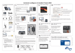
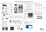
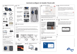
1
of the Xcom-GSM
remote communication set
1. Contents
How to configure and to install the Xcom-LAN
10. Run the Xcom-configurator
8. Turn on the power
3. Mount the different products within the Studer system
The products should be mounted on a smooth surface.
The distance between the Xcom-232i and the Studer
system should not exceed 10 meters.
Xcom-232i
Cellular modem
Choose GSM mode.
The distance between the Xcom-232i and the GSM
modem is maximum 0.25m.
Ask the Internet Service Provider.
All cables you need are provided in the set.
Required for some Internet
Service Providers, leave blank if not.
Enter the SIM card PIN code. Leave it
blank if no code.
Serial cable, 0.25m
Power supply cable
RJ45-Jack, 0.5m
Mounting plate for
Xcom-232i
4.
2.
Sliding pin for
mounting the
modem
the antenna to
the modem
5. Connect
9.
Insert the Micro SD card
into the computer
Eject the SIM card
tray, situated close to
the antenna connector, by pushing the
yellow button next to
it. Place the SIM card
on the tray and reinsert it.
Connect the serial cable between the
modem and the Xcom-232i
b. Connect the power supply cable between
the modem and the Xcom-232i
c.
Connect the communication cable
between the Xcom-232i and the
installation
Additional items needed
a
b
11. Take note of your GUID file
the Micro SD card into
the Xcom -232i
12. Insert
Close the message box and a text file with
your identifier (GUID) will appear. This file
is saved on your "Desktop" or in "My documents". The unique identifier (GUID) is
required to link your installation with your
account on the Xcom portal. Keep it safe.
Remove the SD card from the computer and
insert it into the Xcom-232i. The setup process
will start automatically and normally takes 1
second.
SIM card
Network requirements
• Sufficient GSM network coverage on
the site of the Xtender system
• Network standard: GSM / GPRS / EDGE
/ UMTS / HSDPA / HSUPA / HSPA
• Frequencies: 850 / 900/ 1800 / 1900 /
2100 MHz.
Data traffic
• At least 2MB data per month
• Up to 2MB per day if the datalogger
function is activated. (see table in the
FAQ section for further information.)
b c
7. Set the terminations
It is very important to set the terminations correctly for the functionning of the system.
With one device in the system the termination on the Studer device should be put to T
as in "Terminated". With more than one device in the system all Studer devices should
be put to O as in "Open" apart from the devices at the end of the communication chain.
These devices should be put to T as in "Terminated".
The termination switch next to the two RJ 45 connectors on the Xcom-232i must be set
in position T.
When the LED stops blinking red, the setup is
finished.
ATTENTION!
The Xcom-232i needs to be powered during the
setup process. Otherwise, the configuration will
not be taken into account.
c
15:45
Computer or
mobile phone
Generate the configuration file.
Choose "GSM" as Xcom mode. Then fill in the required fields. Press "Generate" to
save the parameter settings. A window will automatically confirm the successful file
generation.
6. Wiring
a.
External antenna
Enter SIM card into the modem
13. Xcom connects to the server
After the parameters are set and applied,
the Xcom–GSM will automatically connect
to the server and send a confirmation message to the RCC. If there is no message, the
Xcom is not connected to the server. Use
the FAQ at the opposite side of this Quick
guide to see what could have gone wrong.
The Xcom-GSM is sucessfully installed!
Register the installation at: https://xcom.studer-innotec.com in order to control it
remotely with the Xcom-GSM.
© Studer Innotec SA - version 1.0_EN
Micro SD card Communication cable, 2m
with adapter
4O9E7
Studer Innotec SA guarantees the compatibility
of the software updates with the hardware for
one year, starting from the date of purchase.
The updates are no longer guaranteed beyond
this date and a hardware upgrade may be
required. Please contact your reseller for any
additional information on compatibility.
Compatibility
Installation, commissioning, use and maintenance of this device cannot be supervised by
Studer Innotec SA. For this reason, we do not
accept any liability for damages, costs or losses
generated either by an installation that is not
conforming to the prescriptions, by a defective
operation or by poor maintenance. The use
of this device is under the responsibility of
the end-user. This device is neither designed
nor guaranteed for the supply of life support
applications or any other critical application
with potential risks for human beings or for the
environment. We shall assume no liability for
patent infringement or other third party rights
involved in the use of this device.
Disclaimer of liability
No warranty claims will be accepted for damages caused by handling, operation or actions that
are not described in this manual. Damages arisen from the following events are not covered by
the warranty:
•
Overvoltage on the device.
•
Liquid in the device or oxidation due to
condensation.
•
Damage resulting from a fall or a mechanical shock.
•
Modifications carried out without the explicit authorization of Studer Innotec SA.
•
Nuts or screws partially or insufficiently
tightened during installation or maintenance.
•
Damage due to atmospheric overvoltage
(lightning).
•
Damage due to transport or inappropriate
packaging.
Disappearance of original identification
marks.
•
Exclusion of warranty
Copyright © Studer Innotec SA – V 1.0
•
•
•
Low voltage directive 2006/95/CE: EN
60950:2005
EMC directive 2004/108/CE: EN61000-61:2005
RoHS directive: 2011/65/UE
The communication set Xcom-LAN described in
this manual meet the requirements specified in
the following EC directives and norms:
EC DECLARATION OF CONFORMITY
Warnings
•
The installation and commissioning of the
communication sets must be entrusted to
skilled and qualified personnel perfectly
aware of the safety precautions and local
rules in force.
•
All components connected to this device
must be conforming to the laws and regulations in force. Persons without a written
authorization from Studer Innotec SA are
forbidden to do any changes, modifications or repairs whatsoever. Regarding authorized modifications and replacements,
only genuine components shall be used.
•
This device is meant for indoor use only
and must under no circumstances be
exposed to rain, snow or any other humid
or dusty environment.
•
If used in motor vehicles, this device must
also be protected against vibrations by
shock absorbing components.
For any installation, the local and national
norms and regulations in force must be strictly
followed.
Carefully read all safety instructions before
proceeding with the installation and commissioning of the device. Failure to follow these
instructions might constitute a lethal physical
danger but can also damage the functionalities
of the device. Therefore this manual should be
kept close to the device.
Quickguide
Remote communication set for
Xtender systems Xcom-GSM
Generalities
WARRANTY AND LIABILITY
SAFETY PRECAUTIONS
Legal notices
FAQ
LED states
How much data will the Xcom-GSM use per month?
3G modem LED
The basic data usage is about 2 Mega Bytes (MB or Mo) per month. If the Datalogger is enabled,
the quantity of used data will depend on the size of the installation.
Data usage with datalogger enabled per month
Data
usage
System Example of quantity of products in the system
size
Xtender
VarioString VarioTrack
BSP
8MB
S
1
-
1
1
20MB
M
60MB
L
3
2
1
1
9
15
-
1
These calculations do not include the remote control usage.
My Xcom-GSM is well-configured, but doesn’t connect to the server. What should I do?
The modem needs a lot of power to connect to the server. That is why we recommend to not
exceed 10m of cable length and to place the modem the closest possible to the power supply
device (Xtender, VarioTrack or VarioString). Also check that you have activated the SIM card with
the SIM card provider so that it can communicate via the data connection.
State
Indication
Always on
Searching network
Fast blinking (200ms ON, 200ms OFF)
Server connected and transmitting data
Slow blinking (800ms ON, 800ms OFF)
Registered to the operator network
Off
Power OFF
Xcom-232i LED
LED
colour
Red
I entered the wrong PIN code and the Xcom-GSM has blocked my SIM card. What should I do?
After 3 failed attempts, the modem is blocking the SIM card and requires the PUK code (PIN
unblocking key) to unlock the card. You need to insert the SIM card in a phone and unlock it by
entering the PUK code.
State
Blinks
(Ton = 50 % | Toff = 50 %)
Updating process. During the Xcom-232i updating
process (after insertion of a MicroSD card containing the
updates), the signalisation LED blinks in red with a cyclical
ratio of 50 %.
Continuously on
Error during update or back up of the data logger. If
the Xcom-232i detects an error, the signalisation LED is
continuously red.
Blinks (Ton = 10 % | Toff = 90 %)
MicroSD card full. If the Xcom-232i detects that the MicroSD card is full, the signalisation LED blinks in red with a
cyclical ratio of 10 % .
Continuously on
Xcom-portal
I can’t register my new installation. What should I do?
To register a new installation, the installation needs to be:
1. Configured correctly and in accordance with the user manual.
2. Have been connected to the server at least once. In order to validate that the installation has
been correctly configured, the Xcom ID card (see in the System Info menu in another RCC
connected to the system) should indicate either Xcom-LAN for an installation with Xcom-LAN
or Xcom-GSM for an installation with Xcom-GSM.
In order to validate that the connection with the installation is well established, control that the
RCC displays the message "Server connected" when turn on the installation
There are no datalogger files in the Datalogger tab. What should I do?
If the installation is new and the Micro SD card of the Xcom-GSM is empty, it is normal that there
are no files on the server.
To activate the automatic recovery of the Datalogger:
1. The Xcom-GSM needs to have a software version higher than 1.5.36
2. The datalogger needs to be activated on the Xcom-GSM (the green LED should be continuously lit).
3. The Xcom-GSM needs to have a micro SD card inserted continuously.
Green
Orange
Indication
Data logging. When the data logging function is activated, the signalisation LED is green.
Blinks continuously
(Ton = 20 % | Toff = 80 %)
Communication (via RS-232 connection). When the
communication via the RS-232 connection is active, the
signalisation LED blinks in green with a cyclical ratio of
20 %.
Blinks 2x
In operation. The signalisation LED blinks in green twice
when the Xcom-232i is in operation and none of the
above mentioned states is indicated.
On 1.5s
Insertion of the SD card. When inserting an SD card, the
signalisation LED is both red and green simultaneously for
1.5 seconds.
If several of the three states indicated by the red LED light occur simultaneously, they will be
displayed in the following priority order:
•
Update processing
•
Error during updating
•
MicroSD card full
If the two states indicated by the green LED light occur simultaneously, the signal indicating communication via RS-232 connection is reversed (Ton=80% |Toff=20%).