1
Application Note 002
Optimal solar backup
General description
This application note describes how, in a
backup system, to use renewable energy
even when the system is connected to a
grid and the grid feeding is not possible.
Features & advantages
Ideal for backup system with
renewables where there is no feed-in
tariff or where grid feeding is not
possible.
Use all of the renewable energy
available.
Direct use of renewable energy without
cycling energy in the battery(ies) to
avoid their premature aging.
Minimal configuration
Range of inverters
All Xtender Series
o
Xtender
o Software vers.
: 1.3.28 and higher
RCC02 / 03
o Software vers.
: 1.3.32 and higher
o RCC User level : EXPERT
Application Schematic
Page 1 / 7
AN-002-V.1.7.3-10 | © STUDER INNOTEC SA
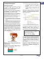
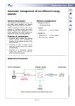
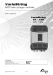
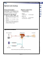
(Figure 1) Backup system using renewable energy without grid feeding
Application Note 002
Detailed description
This parameter sets two zones in a battery(ies) :
Operation description
In a backup system, the power to the end
consumer is taken from the input (grid,
generator…) or, in a blackout situation, from the
DC side (battery(ies), renewables).
Generally, in the case where grid feeding is
not possible, the renewable energy is lost
when the system is powered from input.
A zone below this point, which ensure
an energy reserve for a blackout
situation.
A zone above this point where the
renewable energy in excess can be
stored.
When there is higher production of renewables
than power consumed, it is possible to store this
production in the battery(ies)’s buffer zone for
later use (see figure 4).
This application note shows the possibility to
use the renewable energy of the system even
when the system is connected to a grid.
This operation requires an inverter-charger from
Xtender series with two special functions.
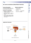
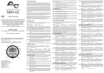
The Smart-Boosti function which adds power
to the AC source according to the input limit
current.
The solar priority function which adjusts the
instantaneous power consumed from the
source according to the battery(ies) voltage.
The operation of the solar priority function is
done with an automatic modification of the input
limit current. The input limit current is decreased
from the initial value (given by the user) if there
is enough energy available at the DC side. The
lower the input current, the more the load is
provided with DC power by the Smart-Boost
function. In this way, the power from the DC
side is integrated in the system and the input
consumption is limited.
(Figure 4) Load profile with renewable energy buffered
An example to determine the value of the
battery(ies) priority voltage considering a
battery(ies) of 24Vdc (Full battery(ies) = 25.5Vdc,
empty battery(ies) = 24Vdc) and a backup zone of
80% of the total capacity of the battery(ies) :
-Full battery(ies) (Fullbat)
= 25.5Vdc
-Empty battery(ies) (Emptybat) = 24.0Vdc
Battery(ies) priority voltage is :
Emptybat + 80% * (Fullbat – Emptybat)
= 24 + 0.8 * (25.5 – 24) = 25.2Vdc
Note that even with the battery priority voltage,
the battery charging proceeds normally and
accepts the absorption and equalization phases.
Thus, it is possible to program absorption and
equalization phases to reduce the problem of
stratification of the acid and the water decrease
in the batteries.
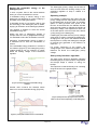
(Figure 2) Smart-Boost function
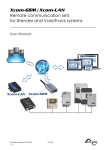
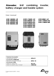
Battery priority voltage, description and
dimensioning
The point where the input limit starts to
decrease is the priority voltage of the
battery(ies), parameter {1297}ii.
But to avoid cycling the batteries too often, it is
necessary to adjust the parameter {1297}
(Battery priority voltage) to a value higher than
the parameter {1143} (Battery voltage level 1 to
start a new cycle).
(Figure 3) Battery priority voltage
Page 2 / 7
Saving the renewable energy or the
battery(ies) life?
In such a system, there is the choice between
storing or not the renewables in excess.
If renewable energy is stored, energy in the
battery(ies) will therefore be cycled, implying a
decrease of the battery(ies) lifetime.
If renewable energy is not stored, it will be lost
but the energy in the battery(ies) will be stable,
implying an extension of the battery(ies) lifetime.
The question is whether to store the excess
renewable energy not?
Where the price of battery(ies) storage is
cheaper than the cost of grid/generator energy,
it is advisable to store the renewables in excess.
Otherwise, if grid/generator energy is cheap, it
is advisable not to store the renewables in
excess.
If the renewable energy production in excess is
not buffered (Figure 5), the battery(ies) priority
voltage should be set, for example, to 0.5Vdc
below the floating voltage of the solar/wind
regulator.
Application Note 002
The battery(ies) priority voltage should also be
set to 0.5Vdc below the floating voltage of the
solar/wind regulator to keep it loaded to a
maximum.
Operating example
For example, if battery(ies) are higher than the
priority voltage and if a solar panel is connected
to the battery(ies) at the DC side, its regulator
(MPPT or other) provides solar power to the
DC-bus. At the same time, the Xtender will take
away the solar power to maintain the DC-Bus at
the priority voltage. This represents a direct use
of the solar power in the final user load, without
cycling energy in the battery(ies).
If battery(ies) are lower than the priority voltage,
solar power is used to recharge the battery(ies).
Charging from the grid is now allowed because
the objective is to keep the battery(ies) charged
for backup time (generator is off, blackout, no
more sun,…).
For proper functioning of the system, the
voltage target of the solar/wind regulator should
therefore be above the battery(ies) priority
voltage.
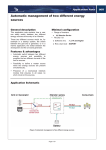
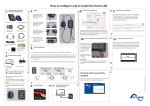
Solar priority function’s algorithm
The solar priority function’s algorithm maintains
the battery(ies) at a proper level for long lifetime
and always keeps a reserve of energy for
backup.
The input limit is reduced linearly over a working
range as shown in the graphic below :
(Figure 5) Load profile without renewable energy
buffered
Another case concerns the situation where
there is no excess renewable energy (Figure 6).
(Figure 4) Graph of Solar priority function. (Current
taken on the AC source depending on the battery(ies))
(Figure 6) Load profile without excess of renewables
Page 3 / 7
Application Note 002
Parameters
Four parametersiii allow controlling the energy
management with different sources :
1. “Battery(ies) priority as energy source”
{1296}
2. “Smart-Boost allowed” {1126}
3. “Battery(ies) priority voltage” {1297}
4. “Maximum current of AC source (Input
limit)” {1107}
Notes
Associated application notes :
AN001 AC source assistance (Smart Boost function)
i
More information about the Smart-Boost is available on
the “AN001 AC source assistance (Smart-Boost
function)”
ii
The voltage values for the battery(ies) priority voltage
{1297} are available at the next page, item : “Battery(ies)
priority voltage”
iii
More information about the source max AC current and
the battery(ies) priority voltage are available at the next
page
Page 4 / 7
Application Note 002
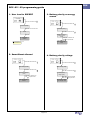
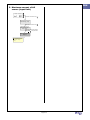
RCC -02 / -03 programming guide
1. User level to EXPERT
Press SET and search with
3. Battery priority as energy
source
:
Press SET and search with
:
User level {5012}
Press SET and insert the code :
SYSTEM {1101}
426468
Press SET and search with
Battery priority as
energy source
{1296}
Press SET :
Your level is
EXPERT
i
:
Press SET, selection Yes
with
and press SET :
Your battery(ies) are
the priority energy
source
The code is available in the
user manual RCC -02 / -03
2. Smart-Boost allowed
Press SET and search with
4. Battery priority voltage
:
Press SET and search with
Basic settings {1100}
Press SET and search with
:
Basic settings {1100}
:
Press SET and search with
Smart-Boost allowed
{1126}
Battery priority
voltage {1297}
Press SET, selection Yes
with
and press SET :
Press SET, adjust the desired
value with
and press SET :
The Smart-Boost is
allowed
Your battery voltage
is at the right value
Page 5 / 7
:
Application Note 002
5. Maximum current of AC
source (Input limit)
Press SET and search with
:
Basic settings {1100}
Press SET and search with
:
Maximum current of
AC source (Input
limit) {1107}
Press SET, adjust the desired
value i with
and press SET :
Your input current is
adjusted
i
The current value [Aac] must be
set according to the size of the
circuit breaker or the grid
capacity
Page 6 / 7
Application Note 002
Notes
__________________________________________________________________________________
__________________________________________________________________________________
__________________________________________________________________________________
__________________________________________________________________________________
__________________________________________________________________________________
__________________________________________________________________________________
__________________________________________________________________________________
__________________________________________________________________________________
__________________________________________________________________________________
__________________________________________________________________________________
__________________________________________________________________________________
__________________________________________________________________________________
__________________________________________________________________________________
__________________________________________________________________________________
__________________________________________________________________________________
__________________________________________________________________________________
__________________________________________________________________________________
__________________________________________________________________________________
__________________________________________________________________________________
__________________________________________________________________________________
__________________________________________________________________________________
__________________________________________________________________________________
__________________________________________________________________________________
Worldwide sales and service
Switzerland
Studer Innotec SA
Rue des Casernes 57
1950 SION / Switzerland
Tel :027 205 60 80 / Fax : 027 205 60 88
Email: [email protected]
Web : http://www.studer-innotec.com
Limitation of responsibility
The use of STUDER INNOTEC SA devices is the responsibility of the customer in all cases. STUDER INNOTEC SA reserves the
right to make any modifications to the product without prior notification.
Page 7 / 7