1
User Manual
Matrix Technologies Corporation ♦ 22 Friars Drive ♦ Hudson, NH 03051
Phone: 800-345-0206 ♦ Fax: 603-595-0505
MAN13266 Rev.C
CONTENTS
INTRODUCTION
3
FUNCTION DESCRIPTION
4-5
PARTS
6
REAR SIDE PANEL
7
BATTERY INSTALLATION
8
ANGLE ADJUSTMENT
9
OPERATION
10
SELECTING LIGHT SEQUENCE
11
TROUBLE SHOOTING
12
MAINTENANCE
13
ORDERING INFORMATION
14
APPENDIX 1: RS232 INTERFACE
COMMAND PROTOCOL
15-17
INTRODUCTION
2
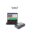
Memowell is a 96 well LED lightbox that aids technicians in remembering where next
to pipet when working with microwell plates. You can choose between six (6) preprogrammed functions:
1.
2.
3.
4.
5.
6.
Single channel light sequences to move via columns.
Single channel light sequences to move via rows.
Single channel light sequences to serpentine through columns.
Single channel light sequences to serpentine through rows.
Multichannel light sequences lighting 8 LED's at a time.
Multichannel light sequences lighting 12 LED's at a time.
Unique light sequences (duplicates, triplicates, discrete wells, etc.) may be created by
using an IBM compatible computer, Memowell applications software and downloading
via an RS232 port on the rear of the instrument. Automatic light advances may be
accomplished by connecting the Memowell to the console of the Electrapette. Each time
the pipet trigger is pressed and liquid manipulated, the lights will automatically advance
to the next series of wells to be pipetted. Lights can also be advanced when using a
manual footswitch. Memowell is A/C powered or available with optional rechargeable
batteries for operation under laminar flow hoods. Memowell can also be ganged
together serially with other Memowells, allowing you to track liquids transferred from
one plate to another.
3
FUNCTION DESCRIPTION
1.
2.
3.
4.
5.
6.
Single Channel dispensing in columns from A-H.
Single channel dispensing in rows from 1-12.
Single channel dispensing in serpentine pattern A-H/H-A, etc.
Single channel dispensing in serpentine pattern 1-12/12-1, etc.
Multi 8-channel dispensing.
Multi 12-channel dispensing.
Standard - Allows you to choose any of the above pre-programmed functions (1-6).
Program - Permits you to recall or store up to 6 custom program.
Enter - Is used to confirm your Standard or Program selection (1-6).
Step - These keys (located on left and right hand side of the keyboard) allow you to
advance your light sequence by pressing whether of the keys. If you keep the key
depressed the LED's will advance rapidly. If key is pressed once only, the LED will
advance one well at a time.
Reverse - Reverses the direction of your pipetting sequence. When the instrument is in
the reverse mode the LED above the reverse key is illuminated.
4
FUNCTION
Tone - Activates or deactivates the beep tone by alternately pressing this key.
Power - Turns the instrument on and off.
Recharge - The LED starts to blink when it is time to recharge the battery. The LED will
start to blink when approximately 20-30 minutes of power remain.
5
PARTS
Your package should include the following parts:
1. The Memowell, Catalog No. 5000.
2. Transformer, Catalog No. 8098.
3. 2 Extra long screws (for adjusting the angle of the Memowell).
4. Communication cord for use with Electrapette Console, Catalog No. 5004.
5. Users Manual
6. 6 Rechargeable AA batteries (Optional in U.S.), Catalog No. 5002.
6
REAR SIDE PANEL
RS 232 Port
Port for footswitch or
Electrapette to Memowell
communications cord.
Inlet for power supply
7
BATTERY INSTALLATION
Note - Battery operation is optional.
Before you start using the Memowell make sure that you have installed 6 AA
rechargeable nickel cadmium batteries.*
1.
2.
3.
4.
5.
Open the Memowell by loosening the four screws at the bottom of the unit.
Lift the lid of the instrument and tilt it forward.
Correctly orient the batteries in the battery holder.
Close the unit and tighten the four screws.
Batteries should be charged for 14-16 hours upon installation to fully charge. This is
accomplished using the power transformer included with the Memowell. The
batteries are charged the fastest with the power in the off mode.
The Memowell may be operated immediately by using the power transformer.
* Caution! Using non-rechargeable batteries can cause SEVERE damage to the
Memowell.
8
ANGLE ADJUSTMENT
To adjust the angle of the Memowell please use the supplied "extra long screws" with
plastic bushings.
Simply unscrew the short screws found on the Memowell and replace with the
supplemental long screws with plastic bushings.
The Memowell can be leveled when these long screws are installed in the front of the
unit.
9
OPERATION
The Memowell is ready for use with charged batteries and/or with power from the wall
transformer.
There are three ways to operate the unit:
1. In conjunction with an Electrapette: Connect the Memowell with the Electrapette by
using the black communications cord supplied.
2. Utilizing a footswitch (optional) in conjunction with an Impact or manual pipettor.
3. Using the step keys on the Memowell keyboard when using an Impact or manual
pipettor.
10
SELECTING LIGHT SEQUENCE
With only a few keystrokes, you can instruct the Memowell to illuminate the appropriate
well sequence.
There are six pre-programmed options of light sequences:
1.
2.
3.
4.
5.
6.
Single channel dispensing in columns from A-H.
Single channel dispensing in rows from 1-12.
Single channel dispensing in serpentine pattern A-H/H-A, etc.
Single channel dispensing in serpentine pattern 1-12/12-1, etc.
Multi 8-channel dispensing.
Multi 12-channel dispensing.
Before selecting your light sequence, make sure the power has been turned on.
To select your light sequence continue to press the Standard key until you reach your
choice for a pre-programmed light sequence (options 1-6). When your choice is
illuminated, press the Enter key.
Example: You want to dispense liquid into a microtiter plate using an eight channel
pipettor. Press the Standard key five times until number 5 is illuminated. Press the Enter
key and the first column will be illuminated.
Note: Use of the Program key requires the RS232 port and the commands in
Appendix I. This allows you to create your own light sequences e.g. dispensing of
duplicate samples, etc.
11
TROUBLE SHOOTING
PROBLEM
The power does not work
The Memowell does not work in
conjunction with Electrapette
The LED's are moving in reverse direction
SOLUTION
1. Check the battery installation
2. Recharge the batteries
3. Connect the unit to a power outlet via
the transformer
1. Check your connection on the rear of
the Electrapette. The correct port has
not been connected or is not fully
connected.
1. Press the Reverse key to cancel the
reverse movement of the light
sequence
12
MAINTENANCE
Note: Do not leave the Memowell exposed to U.V. light for extended periods. Extended
exposure will cause discoloration of the plastic housing.
To clean the instrument, use a soap solution or methanol and gently wipe off the
keyboard.
To recharge the batteries, connect the transformer to the rear of the instrument. To
recharge batteries to full capacity will take approximately 14-16 hours. A quick charge of
6 hours will result in approximately 4 hours of operation. In the event that something not
addressed in this manual should go wrong, or technical questions arise, Matrix
Technologies Technical Services Department is available to address your needs.
Please contact:
Technical Service Department
Matrix Technologies Corporation
22 Friars Drive
Hudson, NH 03051
800-345-0206 or 603-595-0505
In Europe:
Technical Service Department
Matrix Technologies Corporation
13 Croft Road
Wilmslow, Cheshire
UK SK9 The Hollies
+ (44) 1625 549 036
13
ORDERING INFORMATION
CATALOG NO.
DESCRIPTION
5000
Memowell Lightbox microplate
memory device, includes Electrapette
connection cable, leveling feet, and
a Swiss Army Knife
5001
Footswitch for Memowell or Electrapette
Console
5002
Rechargeable Memowell Batteries 6/pack
5003
Serial Communications Cable
5004
Electrapette Connection Cable
Memowell RS-232 INTERFACE
Command Protocol
14
Rev 1.00
12/19/89
Applies to Memowell Rel 1.00
This is a protocol for commanding the Memowell via the RS-232 port. The Memowell is
commanded either for immediate execution or for program mode (commands are stored
for later execution).
Each LED has a unique identifier (address) for programming. The LED identifiers are as
follows (looking down on the face of Memowell):
Top Left
01
02
03
04
05
06
07
08
09
10
11
12
13
14
15
16
Top Right
17
18
19
20
21
22
23
24
25
26
27
28
29
30
31
32
33
34
35
36
37
38
39
40
41
42
43
44
45
46
47
48
49
50
51
52
53
54
55
56
57
58
59
60
61
62
63
64
65
66
67
68
69
70
71
72
73
74
75
76
77
78
79
80
Bottom Left
81
82
83
84
85
86
87
88
89
90
91
92
93
94
95
96
Bottom Right
Memowell status LEDs are not controllable by the host computer.
Memowell commands are sequences of ASCII (printable) characters. Each command is
terminated by a carriage return (CR) (but no line feed (LF)). The CR causes Memowell
to execute the just-received command. As characters are passed to Memowell,
Memowell echoes them. The terminating CR is echoed as a CR+LF. The echo of the
CR as a CR+LF signals the host computer that Memowell has received and executed
the just-received command.
The Memowell RS-232 interface consists of the following 5 lines:
Pin
Pin
Pin
Pin
Pin
2
3
4
5
7
Data from host into Memowell
Data from Memowell out to host
Request to Send from host into Memowell
Clear to Send Used by Memowells to claim use of pin
Signal ground
A +6V to +12V level on pin 4 signifies that the host is ready to receive characters. Pin 5
is used in multi-Memowell networks to allow only one Memowell at a time to transmit
data back to the host. Pin 5 should be ignored by the host. The two DB-25 connectors
are connected in parallel.
15
The Memowell command set is:
#n
Attention. This command initializes the communications with Memowell. The n is
the Memowell address, used in multi-Memowell configurations where 2 to 9 Memowells
share a common RS-232 link with the host. In this case, communications is established
with the Memowell that has been previously assigned address n. Memowell n responds
by echoing the n (its address) and a colon. The default address for all Memowells is 0.
A 0-address Memowell will respond to any addressed attention. Also, the attention
command issues with an address of 0 ("#0,CR") will cause every Memowell on the
network to respond ( a mess if there are actually multiple Memowells on-line).
X
Hang-up character. This character terminates the communications with the active
Memowell. As soon as the command is received, the active Memowell will go off-line.
The Memowell echoes the X, then echoes the CR as a CR+LF.
An
Assign address n. This command assigns the address n to a single Memowell for
later use in a Multi-Memowell configuration. The value of n can be 1 to 9. The default
address is 0, for use only on single-Memowell configurations. Executing the A command
on a Multi-Memowell configuration will cause mass confusion as all Memowells will be
assigned the same address. The host program must ensure that this command is not
issued into a Memowell network. If it is, the network will have to be disassembled, and
Memowells put on line individually for reassignment of addresses.
C
Clear the display. Turn off LEDs 1 through 96.
Nn
Fn
Bn
T
Wn
S
Turn on LED n. Here n can be between 1 and 96.
Turn off LED n, n between 1 and 96.
Blink LED n, n between 1 and 96
Sound the Tone.
Wait unconditionally for n units of time.
Wait for a footswitch depression.
Pn
Program number n. Here n can be 1 to 6. Executing this instruction causes
program n to beerased and the following commands to be stored as program n.
Commands are stored until an asterisk followed by CR is sent. The asterisk is the last
command stored, and marks the end of the program for Memowell. No facility for
loading part of a program is provided. The entire program must be loaded at one time.
Rn
Read program n, for n between 1 and 6. Executing this instruction causes
Memowell to dump the contents of program n over the RS-232 link to the host. The
Memowell expects no echo each. The program is read until the first asterick is
encountered, signifying the end of the program.
D
Display Memowell revision and unit address.
16
Programs can be demonstrated and debugged using the immediate mode (issuing N, F,
B commands). Each program in Memowell can contain up to 840 characters. This
corresponds to about 250 commands. When full, the Memowell will refuse to echo
characters. The programming can be restarted by another P command. The
responsibility for keeping track of the program length rests with the host computer.
The host computer can issue commands to Memowell 1, creating some display pattern.
Then it can hang up on Memowell 1, and command Memowell 2 to display some
independent display pattern. Meanwhile, Memowell will continue to display as
previously commanded. A user can interrupt any Memowell that is not in active
communications with the host by selecting a program.
This protocol is subject to change.
17