1
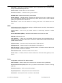
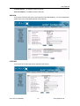
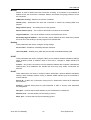
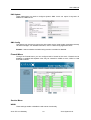
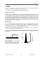
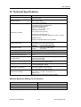
Arctic User’s Manual Arctic IEC-104 Gateway Version 1.4.8 October 2005 User’s Manual Copyright and Trademark Copyright 2004-2005, Viola Systems Ltd. All rights to this manual are owned solely by Viola Systems Ltd. (referred elsewhere in this User’s Manual as Viola Systems). All rights reserved. No part of this manual may be transmitted or reproduced in any form or by any means without a prior written permission from Viola Systems. Ethernet™ is a trademark of XEROX Corporation. Windows™ and Internet Explorer™ are trademarks of Microsoft Corporation. Netscape™ is a trademark of Netscape Communications Corporation. All other product names mentioned in this manual are the property of their respective owners, whose rights regarding the trademarks are acknowledged. Viola Systems Ltd. Lemminkäisenkatu 14-18 B FIN-20520 Turku Finland E-mail: [email protected] Technical Support Phone: +358 20 1226 226 Fax: +358 20 1226 220 E-mail: [email protected] Internet: http://www.violasystems.com Arctic IEC-104 Gateway 2 Viola Systems Ltd. User’s Manual Disclaimer and Revisions Viola Systems reserves the right to change the technical specifications or functions of its products or to discontinue the manufacture of any of its products or to discontinue the support of any of its products without any written announcement and urges its customers to ensure that the information at their disposal is valid. Viola software and programs are delivered “as is”. The manufacturer does not grant any kind of warranty including guarantees on suitability and applicability to a certain application. Under no circumstance is the manufacturer or the developer of a program responsible for any damage possibly caused by the use of a program. The names of the programs as well as all copyrights relating to the programs are the sole property of Viola Systems. Any transfer, licensing to a third party, leasing, renting, transportation, copying, editing, translating, modifying into another programming language or reverse engineering for any intent is forbidden without the written consent of Viola Systems. Viola Systems has attempted to verify that the information in this manual is correct with regard to the state of products and software on the publication date of the manual. We assume no responsibility for possible errors which may appear in this manual. Information in this manual may change without prior notice from Viola Systems. Revision History: 01/2004 Manual released, Version 1.0 06/2004 Minor modifications and HW update, Version 1.1 11/2004 HW information added (DIP-switches, console switch), Version 1.2 01/2005 Serial Gateway information added and chapter regarding IO modified, Version 1.3 10/2005 General text related corrections / Chapter 5 - Firewall rewritten Version 1.4 Arctic IEC-104 Gateway 3 Viola Systems Ltd. User’s Manual Declaration of Conformity (according to ISO/IEC Guide 22 and EN 45014) Manufacturer’s Name: Viola Systems Ltd. Manufacturer’s Address: Lemminkäisenkatu 14-18 B FIN-20520 Turku Finland declares that this product: Product Name: Arctic IEC-104 Gateway conforms to the following standards: EMC: EN 55022 Emission Test (Class A) 1. Radiated Emissions (30-1000MHz) 2. Conducted Emissions (0.15-30MHz) EN 50082-1 Immunity Test 1. IEC 801-3: Radio Frequency Electromagnetic Field 2. IEC 801-2: Electrostatic Discharge 3. IEC 801-4: Fast Transients, AC Power Ports and Signal cables Supplementary Information: “The product complies with the requirements of the Low Voltage Directive 73/23/EEC and EMC directive 89/336/EEC.” Warning: This is a Class A product. In a domestic environment this product may cause radio Interference which may make it necessary for the user to take adequate measures. Manufacturer’s Contact Information: Viola Systems Ltd. Lemminkäisenkatu 14-18 B FIN-20520 Turku Finland Phone: +358 20 1226 226 Fax: +358 20 1226 220 Arctic IEC-104 Gateway 4 Viola Systems Ltd. User’s Manual Warranty and Safety Instructions Read these safety instructions carefully before using the products mentioned in this manual: Warranty will be void if the product is used in any way in contradiction with the instructions given in this manual or if the product has been tampered with. The devices mentioned in this manual are to be used only according to the instructions described in this manual. Faultless and safe operation of the devices can be guaranteed only if the transport, storage, operation and handling of the devices is appropriate. This also applies to the maintenance of the products. To prevent damage both the product and any terminal devices must always be switched OFF before connecting or disconnecting any cables. It should be ascertained that different devices used have the same ground potential. Before connecting any power cables the output voltage of the power supply should be checked. This product is not fault-tolerant and is not designed, manufactured or intended for use or resale as on-line control equipment or as part of such equipment in any hazardous environment requiring failsafe performance, such as in the operation of nuclear facilities, aircraft navigation or communication systems, air traffic control, direct life support machines, or weapons systems, in which the failure of Viola Systems manufactured hardware or software could lead directly to death, personal injury, or severe physical or environmental damage. Arctic IEC-104 Gateway 5 Viola Systems Ltd. User’s Manual Contents Copyright and Trademark ....................................................................................................................... 2 Disclaimer and Revisions........................................................................................................................ 3 Declaration of Conformity........................................................................................................................ 4 Warranty and Safety Instructions............................................................................................................ 5 Contents .................................................................................................................................................. 6 1. Introduction ......................................................................................................................................... 8 About this User’s Manual ........................................................................................................... 8 The Arctic Platform..................................................................................................................... 9 2. Physical Interfaces ............................................................................................................................ 10 Front Panel Description............................................................................................................ 10 Side Panel Description............................................................................................................. 13 Back Panel Description ............................................................................................................ 13 Product Information Label ........................................................................................................ 14 Firmware Version ..................................................................................................................... 14 3. Getting Started .................................................................................................................................. 15 Unpacking the Arctic ................................................................................................................ 15 Installation of the Arctic ............................................................................................................ 15 Setting of the IP Address Using a Console.............................................................................. 16 Setting of the IP Address Using an HTML Browser................................................................. 17 4. Arctic Configurator Tool .................................................................................................................... 18 Login to Arctic Configurator ..................................................................................................... 18 General Usage of the Arctic Configurator ................................................................................ 18 5. Arctic Software Configuration ........................................................................................................... 19 System Menu ........................................................................................................................... 19 Network Menu .......................................................................................................................... 19 Firewall Menu........................................................................................................................... 23 Service Menu ........................................................................................................................... 23 Application Menu...................................................................................................................... 25 Tools Menu .............................................................................................................................. 25 Default settings ........................................................................................................................ 25 6. I/O Interface (optional) ...................................................................................................................... 26 Digital Inputs (IO-8-2 and IO-8-1-1 only).................................................................................. 26 Digital Outputs (IO-8-2 and IO-8-1-1 only)............................................................................... 26 DC Output ................................................................................................................................ 27 Analog Input (IO-8-1-1 only) .................................................................................................... 27 7. GPRS ................................................................................................................................................ 28 Placing Arctic IEC-104 ............................................................................................................. 28 GPRS Antenna......................................................................................................................... 28 SIM Card and Card Holder ...................................................................................................... 29 Configuring Arctic IEC-104 Gateway Settings ......................................................................... 29 Useful GSM/GPRS Information ............................................................................................... 30 8. IEC-104 application settings ............................................................................................................. 31 General settings ....................................................................................................................... 31 Serial settings........................................................................................................................... 32 Network settings....................................................................................................................... 34 IEC-104 settings....................................................................................................................... 35 IEC-101 settings....................................................................................................................... 38 IO extension ............................................................................................................................. 44 Other settings........................................................................................................................... 48 9. Troubleshooting ................................................................................................................................ 49 Common Problems .................................................................................................................. 49 10. Technical Specifications.................................................................................................................. 50 Absolute Maximum Ratings for I/O Interface ........................................................................... 50 11. Limited Warranty ............................................................................................................................. 51 Coverage.................................................................................................................................. 51 Arctic IEC-104 Gateway 6 Viola Systems Ltd. User’s Manual Excluded Products and Problems............................................................................................ 51 Remedies ................................................................................................................................. 51 Obtaining Warranty Service ..................................................................................................... 51 12. Technical Support ........................................................................................................................... 52 Contacting Technical Support.................................................................................................. 52 Recording Arctic Information.................................................................................................... 52 Arctic IEC-104 Gateway 7 Viola Systems Ltd. User’s Manual 1. Introduction Viola Arctic IEC-104 Gateway product offers industrial quality connectivity devices for the IEC 60870 protocol family. IEC-104 is a vendor-independent communication standard for electricity industry. With Arctic IEC-104 Gateway conventional IEC-101 devices can be attached to a modern TCP/IP based IEC-104 control system. Ethernet and GPRS network interfaces provide a seamless communication solution for most of the applications. About this User’s Manual This User’s Manual describes the operation of the Arctic IEC-104 Gateway product. All devices in this User’s Manual are referred to as Arctic, unless otherwise mentioned. This manual provides introductory information as well as detailed instructions on how to set up and manage the Arctic as part of a network environment. It is intended for anyone involved in installing and managing Arctic devices. It is assumed that the reader of this manual is familiar with basic working principles of Internet technology. Arctic IEC-104 Gateway 8 Viola Systems Ltd. User’s Manual The Arctic Platform The Arctic platform utilizes a number of wireless or fixed line interfaces depending on your specific requirements. Arctic is a customizable technology allowing users to develop solutions for their own applications. Arctic devices have been designed to withstand the requirements of extreme environments and industrial use. Technical Features Summary The Arctic is available with various networking and I/O options. The following table shows the functional components in the Arctic platform. Details of each component are also listed below. HARDWARE CPU Platform: • 32-bit RISC microcontroller • 32 MB RAM • 8 MB Solid state FLASH memory Application Services • HTTP server, CGI • FTP client • Telnet server • SSH server and client • Temperature sensor • Real Time Clock • Syslog • DHCP server and client • Status querying using SMS • Serial connection (Serial GW) • IEC-104 communications Network Interface • 10/100 Base-T Ethernet (RJ45) Device Interface • 2 Serial ports (RS-232, RS-485) Mechanics • Aluminum frame • Attachment rail for optional and custom mounting tools Manufacturing Options: • I/O-board • Backup Battery SOFTWARE Operating System • Multitasking embedded µCLinux Management and Configuration: • Web user interface • Console port • Telnet Supported Protocols • PPP, IP, ICMP, UDP, TCP, ARP, DNS, DHCP, FTP, TFTP, HTTP Arctic IEC-104 Gateway 9 Viola Systems Ltd. User’s Manual 2. Physical Interfaces Depending on the model, the Arctic unit contains two or three panels for interface connections and status indication. These panels are: 1. Front panel. An example of a typical configuration is shown in the top figure. This panel includes all connectors and switches for the device operation, optional input/output connectors and the connectors for network and serial interface. 2. Back panel. The GPRS antenna connector and SIM-card holder are shown in bottom figure. 3. Side panel. The side panel contains all LEDs which indicate the status of the device. Front Panel Description The front panel of the Arctic consists of the following connectors and switches: I/O pin1 pin15 RS1 DC IN RS2 1 5 6 1 + 9 Note: 8 9 6 1 7 0 ON 1 3 1. 2. 3. 4. 5 1 OFF 2 8 4 Power supply connector Power switch Console serial port (RS1) Console switch 5 6 5. 6. 7. 8. DIP switches Application serial port (RS2) Ethernet connector I/O connector (optional) Some of the connectors are present only with specific manufacturing options. Arctic IEC-104 Gateway 10 Viola Systems Ltd. User’s Manual The Arctic has rails to enable wall or rack mounting. The front panel contains slots for nuts or other mounting accessories (optional) in order to gain access to these rails. Power Supply Connector The Arctic has a 6 – 26 VDC power supply connector shown below: Pin 1 is positive (+) Pin 2 is negative (–) 1 2 The unit is protected against reversed polarity. Power Switch Enables or disables the operation of the Arctic. Console Enable Switch Enables or disables console access. When it is disabled, both serial ports may be used as an application serial port. When the switch is in the right position, RS1 is in serial port mode and when in the left position, RS1 is in console mode. DIP Switches Selects application port (RS-2) mode and settings (RS-232 or RS-485). By default all are set to “0” when the port is acting as an RS-232. DIP switches 2-4 apply only when RS-485 mode is selected by DIP switch 1. Number 1 Function RS-232/RS-485 2 HALF/FULL 3 BIAS 4 TERMINATION State “0” = RS-232, ”1” = RS-485 “0” = half “1” = full “0” = OFF “1” = ON “0” = OFF “1” = ON Explanation Selects RS-port operation Selects between half-duplex (2wire) and full-duplex (4-wire) RS-485 biasing RS-485 termination Serial Ports (RS-232, RS-422/485 -connectors) Arctic has two serial port connectors. These are 9-pin male connectors (DB9). A null modem cable may be used to connect the Arctic to a serial device or a PC. The Arctic supports CTS/RTS flow control. The figure of Arctic’s DB9 (DTE) Male connector is shown below: 1 5 6 9 The serial port 1 is a full RS-232 -port. The pin description of this port is as follows: Arctic IEC-104 Gateway 11 Viola Systems Ltd. User’s Manual Pin Number Name Direction Explanation 1 DCD IN Data Carrier Detect 2 RXD IN Received Data 3 TXD OUT Transmitted Data 4 DTR OUT Data Terminal Ready. Handshake output 5 GND - Signal ground. 6 DSR IN Data Set Ready. Handshake input 7 RTS OUT Ready To Send. Handshake output 8 CTS IN Clear To Send. Handshake input 9 RI IN Ring Indicator The serial port 2 can be configured either as a half RS-232 or an RS-422/485 (DTE Master). The pin description of this port is as follows Pin Number RS-422 RS-485 Direction Explanation RS-232 1 NC NC Not connected NC 2 RXD+ IN Non-inverted data input RXD 3 TXD– OUT Inverted data output TXD 4 NC NC Not connected NC 5 GND - Not connected GND 6 NC NC Not connected NC 7 TXD+ OUT Non-inverted data output RTS 8 RXD– IN Inverted data input CTS 9 NC NC Not connected NC Note: See serial port 1 See serial port 1 Make sure that you DO NOT connect RS-422 or RS-485 devices to a port which has been configured to operate as an RS-232 port. Ethernet Connector Arctic has an RJ45 connector for 10/100 Mbps Ethernet connection. Maximum length of the Ethernet cable is 100m. Note: The cross-connected cable is only for connecting the Arctic to the PC’s network interface card. When connecting to a local network (e.g. hub or switch), a direct Ethernet cable must be used. The figure and pin description of the Arctic’s RJ45 Ethernet connector is as follows: 8 1 Arctic IEC-104 Gateway Pin Name Number Direction Explanation 1 2 3 4 5 6 7 8 IN IN OUT Data Receive Positive Data Receive Negative Data Transmit Positive OUT Data Transmit Negative Rx+ Rx– Tx+ NC NC Tx– NC NC 12 Viola Systems Ltd. User’s Manual I/O Connector (optional) The Arctic is available with 2 different (manufacturing option) I/O connectors. The basic configuration consists of 8 digital inputs, 2 digital outputs (see Chapter 6). Side Panel Description The side panel of the device contains all LEDs which are used to indicate the status of the Arctic. The LEDs are numbered from 1 to 10 starting from the rear panel side. A detailed description of each LED is listed below: LED number 1 LED Name Battery Error 2 Status 3 Power/Error 4 Function 5 Collision 6 Activity 7 ---red/green1 8 ---red/green 2 9 ---red/green 3 10 GPRS LEDs state Description Backup battery status (optional) Green Not lit Red Green, Blinking Power switched ON No power Watchdog operation OK Off Green, Blinking Steady On Green, Blinking Normal operation Network collision Operation voltage connected Packets received from the network Off Green, blinking Red, blinking No GPRS/GSM traffic GPRS traffic Back Panel Description The Arctic IEC-104 Gateway has an antenna connector and a slot for a SIM card on the back panel. 1. FME connector for an antenna. 2. SIM Card slot. Note: It is recommended NOT to insert or remove the SIM card while the GPRS module is in operation. The SIM card contents may become corrupted if the card is removed while the GPRS module is writing data to it. Arctic IEC-104 Gateway 13 Viola Systems Ltd. User’s Manual Product Information Label The product information label on the underside of the Arctic contains the following information: 1. Product type 2. Serial number 3. MAC address. The Ethernet address (MAC address) of the unit is printed on the product label (see below). Each address code starts with the digits “00:06:70”, but the remaining six digits are unique for each unit. Firmware Version The Arctic firmware version may be checked from the Viola Configurator startup page. (System/Information). It is also possible to get the firmware version by issuing command firmware in console. Arctic IEC-104 Gateway 14 Viola Systems Ltd. User’s Manual 3. Getting Started Unpacking the Arctic Arctic is delivered in a bulk package containing only the device itself (with possible internal options). A separate Arctic Accessory Kit (ordered separately) contains the following items: • • • Power supply and cable Cross-over Ethernet Cable Null modem cable. If any of the items are missing or are damaged, please contact Viola Systems Ltd. All packaging materials are recyclable. Viola Systems urges its customers to follow environmental regulations regarding the disposal of all materials. Installation of the Arctic The Arctic can be installed horizontally on a flat surface e.g. on a desk or a rack. When installing Arctic models with wireless connectivity options it should be remembered that highfrequency radio waves need to be taken into account. The surrounding environment affects the range of radio signals. Therefore, if you are using an Arctic with antennas directly mounted to the antenna connector, try to avoid placing the Arctic where the radio signal might be disturbed (“shadowed”) by nearby obstacles. Also large metallic surfaces (racks) may have a highly detrimental effect on the antenna performance. In case of metal racks or surfaces it is recommended to use an external antenna with an appropriately selected cable. By following these precautions the Arctic may be installed more freely. The aluminum case of the Arctic contains rails for wall mounting. Both broad sides contain two rails and the narrow side opposite to the LED panel contains one rail. These rails allow a flexible selection of the optimum mounting direction. To mount the Arctic on a wall using optionally available mounting tools can be used. Arctic IEC-104 Gateway 15 Viola Systems Ltd. User’s Manual Setting of the IP Address Using a Console Before installation you need to find out the required network settings. These include the IP Address, Netmask and Gateway Settings used by the Arctic. The local network administrator can provide them to you or you can ask for them from your Internet Service Provider. Note: If possible, it is recommended to use an HTML browser to set up network settings as described in the next chapter. If using a console, please follow the procedure below: 1. Before beginning, turn off the power from all devices and check that the power switch of the Arctic is in the “OFF” position. 2. Connect a serial cable to the console serial port (RS1) and an Ethernet cable to the RJ45 connector. 3. Switch the Arctic on by toggling the power switch to “ON” position. 4. After booting the Arctic, open a terminal connection to the Arctic using the following serial communication settings: “19200-8-N-1” and “NO HW or SW handshaking”. 5. Enter login and password when Arctic prompts you for them. The default password is empty. 6. Wait for the Linux prompt and then enter the following command with <ip_address> replaced with the IP address of your choice. echo <ip_address> > /proc/config/ipaddr 7. You can check that the IP address was set up correctly by entering the following command in the Linux prompt. cat /proc/config/ipaddr 8. By repeating step 5 you can set other network settings by replacing the keyword ipaddr with one of the following keywords: netmask, gatewayip 9. Reboot the Arctic for the settings to take effect. ViolaArctic login: root Password: (N. J 4NL .NN` 4NN_ .NN` 4NN) (NNN` __ __ _ ______ _ __ `NNNNL _JNNF \ \ / / | | / __ \ | | / \ (NNNNNNL___JNNNNNF \ \ / / | | | | | | | | / /\ \ (NNNNNNNNNNNNNN` \ \/ / | | | |__| | | |__ / / \ \ `NNNNNNNNNNNN) \__/ |_| \______/ |____|/_/ \_\ NNNNNNNNNNNN` JNNNNNNNNNNN. s y s t e m s NNNNNNNNNNNNL (NNNNNNNNNNNNN) NNNNNNNNNNNNNNNN) _NNNN" 4NNNNL JNN"` 4NNN. For further information check: .JNN NNN. http://www.violasystems.com/ .NF` 4NL .JF `"N # echo 172.16.16.2 > /proc/config/ipaddr # cat /proc/config/ipaddr 172.16.16.2 Arctic IEC-104 Gateway 16 Viola Systems Ltd. User’s Manual Setting of the IP Address Using an HTML Browser This is the recommendable way to set up the network parameters. It is an easy-to-apply solution if the computer used for configuration has been properly configured. Follow the procedure listed below: 1. Connect to the Arctic using your HTML browser. The default IP address of the Arctic is “10.10.10.10” (netmask “255.0.0.0”). 2. From the initial page click Start Configurator and enter login information in the following page. Username is root and by default no password is set (just leave the field empty). 3. Navigate to Network page (1 in the picture) and from there to Ethernet subpage (left menu, 2). 4. Enter the IP address (and other network settings) of your choice and click Apply (3) and then Commit (4) to store the settings. 5. Reboot the Arctic for the settings to take effect. Note: Arctic default password is empty. Remember to set the password before connecting the Arctic device to a public network. Arctic IEC-104 Gateway 17 Viola Systems Ltd. User’s Manual 4. Arctic Configurator Tool The Arctic Configurator is a tool which allows the user to manage the properties of the Arctic device by using a user-friendly, www-based interface. You only need a computer with an HTML browser and a working connection to the Arctic to be able to use the web configurator. With the Arctic Configurator you can set important parameters, receive status information, and set variables that control which applications and processes run on the Arctic board. Login to Arctic Configurator To start using the Arctic Configurator, just open the URL in which the Arctic which you want to configure is located. On the Viola Arctic main page, select the Start Configurator link. First, the Arctic Configurator will ask you for the password for the Arctic device root-account. Enter the correct password in the box provided and press the login-button to start the Arctic Configurator. Note: Default password for root is empty. Remember to set the password before connecting the device to a public network. General Usage of the Arctic Configurator After a successful login, the Arctic Configurator will display the main screen. This consists of the main navigation menu on the top, the secondary navigation bar on the left, and the main screen containing the currently active content and controls. When first starting the program, the System/Information screen will be shown in the main content area. The main navigation-menu on the top of the screen is used to navigate between the different subsets of settings available. Selecting an item from the main menu will display the available items related to this subset in the secondary navigation bar, selecting the first of these to be shown in the main content area. The secondary navigation-bar on the left contains the groups of parameters in this subset. Selecting an item from this menu will display the content related to the selected group in the main content area. In the bottom of the secondary navigation-bar is a group of three buttons which are always visible: Commit , Reboot , and Logout. The Commit-button is used to save the memory-resident data for "soft" parameters permanently to disk. Note that the values for the previous parameters are not saved to disk unless the Commit-button is pressed. The Reboot-button, as the name suggests, will reboot the Arctic. The Logout button will end the current session and return to the login-screen. Arctic IEC-104 Gateway 18 Viola Systems Ltd. User’s Manual 5. Arctic Software Configuration System Menu The System-menu contains items that are relevant to the Arctic board itself. It allows the user to view information about the system or the current executing environment and to set the date and time. Information – submenu contains general information about the Arctic device. Information on this submenu should be provided if possible when contacting Viola Systems technical support. Time – submenu contains time information. Arctic has a real time clock with battery backup and time information may be adjusted here. Note: Updated time data won’t be saved permanently until the Commit button is pressed. Until then, it will be stored only in resident memory. Environment – submenu contains information about the Arctic device memory usage, uptime and inside temperature. Password – submenu contains password changing. The default password is blank. When changing the password for the first time, the same password has to be written in all three boxes. Network Menu Through the Network-menu you can access sub items to control the various network interface properties. The menu contains items for Ethernet, VPN and GPRS interfaces. Also Email, Proxy and firewall settings are located in this submenu. Summary page shows which interfaces are up and also routing information: Ethernet Configuration for the Arctic Ethernet Interface: Override Ethernet configuration by DHCP – If this parameter is Enabled Arctic gets the IP address and other related information from a local DHCP server. When enabled, all other settings are disabled on this page. Arctic IEC-104 Gateway 19 Viola Systems Ltd. User’s Manual Host name – Sets the Arctic device hostname. This is important to set up correctly when using a Viola M2M Gateway and VPN. Domain name – Domain name for name resolution. Ethernet IP address – IP address used by eth0 interface. Network mask – Network mask used by eth0 interface Default gateway – Default gateway used when the direct route to host or network is not know. This parameter applies to eth0 interface only. When GPRS or VPN is used as default gateway this parameter has to be set to 0. DNS servers - Name server IP address for resolving host names to IP address and vice versa. GPRS GPRS settings include APN and other settings for GPRS network connectivity. More details of GPRS connectivity is in Chapter 7. GPRS enabled – When set to yes, GPRS interface is automatically attached to GPRS network. Access Point Name (GPRS) – GPRS APN name where the connection is made. PIN code– SIM card pin code. Led indication – In Data only mode GPRS LED blinks green when transmitting data. In Informative mode LED blinks also when connected to GPRS network without data transfer (GPRS context is active). GPRS username – Username used for authentication if APN requires it. GPRS password – Password used for authentication if APN requires it. PPP idle timeout – Maximum idle time for GPRS interface. If interface has been idle for this period, the GPRS connection is restarted. Maximum MTU value – Maximum transfer unit for GPRS. Default route – If enabled, GPRS is used as default route. Ethernet default gateway has to se to 0. Dial-in Configuration for the Arctic PPP dial-in Interface. Dial-in enabled – When enabled, PPP connections can be made to Arctic (GSM data). Require authentication (PAP) When set to yes password authentication is used for incoming data calls. Required username – PAP username allowed login. Required password – PAP password used for authentication. Idle timeout – Idle time before PPP connection is terminated. Arctic IEC-104 Gateway 20 Viola Systems Ltd. User’s Manual Local IP address – IP address used in PPP peer. Peer's IP address – IP address used in PPP peer. SSH-VPN Arctic has a VPN client that can be used with the Viola M2M Gateway. For VPN configuration, please refer to the Viola M2M Gateway User’s Manual. L2TP-VPN Arctic has a L2TP client that can be used with L2TP server. Arctic IEC-104 Gateway 21 Viola Systems Ltd. User’s Manual Monitor Monitor is used for GPRS and VPN connection checking. If connection to the selected IP address is lost, the connection is restarted. Monitor uses ICMP echo (ping) packets to check the connection. ICMP Echo sending – Selects if the monitor is enabled. Interval (sec) – Determines how often the connection is checked by sending ICMP echo packets. Reply timeout (secs) – The waiting time for reply packets. Retries timeout (secs) – The number of tries before connections are restarted. Target IP address – The host IP address to which echo packets are sent to. Secondary target IP address – The secondary host IP address to which ICMP echo packets are to be sent if the sending to primary target host IP address fails. Routing These parameters are used to configure routing settings: Act as router – Enables IP forwarding between interfaces. Use Proxy ARP – Enables proxy ARP. May be used with Viola M2M Gateway VPN. S-NAT These parameters are used to configure S-NAT (source network address translation) settings. When enabled, private IP address used in local LAN is changed to GPRS interface IP address. From IP – Only S-NAT connections from the defined IP address are accepted. If defined with wildcard (0/0), all IP addresses are handled the same way (only S-NAT connections are allowed). D-NAT These parameters are used to configure D-NAT (destination network address translation) settings. When enabled, packets coming to defined GPRS interface port are forwarded to local IP address. Source IP – D-NAT only connections coming from IP. Wildcard 0/0 means all IP addresses are D-NATted. Protocol – Chooses which protocol is port forwarded. If “ANY” is chosen, other parametes are disregarded. Dest.port – Chooses which GPRS interface is port forwarded to local Ethernet. Redirect to IP – Chooses where port forwarding is done to. Redir. port – Chooses which port port forwarding goes to. Arctic IEC-104 Gateway 22 Viola Systems Ltd. User’s Manual DNS Update These parameters are used to configure dynamic DNS. Arctic can report it’s dynamic IP address to a DNS server. SMS Config This feature may be used to monitor the Artic status and to issue simple commands remotely via SMS messages. For detailed information, refer to “SMS Config Application Note”. Enabled - Selects whether the SMS Config function is enabled or disabled. Firewall Menu Through the Firewall-menu you can configure built-in firewall of the Arctic. Firewall can be disabled or enabled and separate rules may be created for GPRS to Arctic, GRPS to LAN and LAN to GPRS. Service Menu WWW These settings enable or disable the web server functionality. Arctic IEC-104 Gateway 23 Viola Systems Ltd. User’s Manual Web Server – Disables or enables the www server. Web Configuration Access - Disables or enables web configuration access. Note: If you disable the web access settings, web configurator stops functioning and you will have to enable it via console if you should need to use it again later. SSH SSH server is available in Arctic for secure connections. Configuration file located at /etc/sshd_config may be edited manually. SSH Server – Enables or disables the SSH server. Telnet Telnet server may be used to make terminal connections to the Arctic device shell. A more secure way of performing remote management is based on the SSH. Telnet server- Enables or disables the telnet server. DHCP DHCP server listens to broadcast DHCP queries and assigns IP address for host from the configured pool. If needed, Arctic can act as a DHCP server. This is suitable for small remote networks that have for example few laptops connected to the Arctic via an Ethernet hub or a switch. DHCP Server – Enables or disables the DHCP server. Note: Configuring the DHCP server in an erroneous way may cause your network to function badly or may prevent functioning altogether. Consult your network administrator for necessary information before setting up the service. Arctic IEC-104 Gateway 24 Viola Systems Ltd. User’s Manual Application Menu Application menu contains the serial device server application. With this application serial devices can be connected to the Arctic Gateway and used over the TCP/IP network. Serial GW Serial gateway can be enabled from this menu. When enabled in “Server” operation mode, TCP/IP (or UDP) connections can be made to the Arctic (Local Server Port). When Serial GW is in “Client” operation mode, Arctic Gateway sends the received serial data via TCP/IP to host (Remote IP Address or host) to remote host (Remote Port). IEC-104 Serial device is connected to Arctic RS2 serial port. The RS2 serial port can be used either as an RS-232 or an RS-485 type port (IEC-104). To enable serial gateway functionality on RS1 the console (RS1) port, the console switch has to be set to “0”. For example, a device connected to an Arctic GW application (when in server operation mode) serial port could be accessed with telnet utility as follows: telnet <Arctic IP Address> 2404 Tools Menu The Tools menu provides the access to web based tools used for troubleshooting with the Arctic. It is possible to execute simple shell commands through the Web console. Also GPRS information can be obtained from “Modem Info” menu. Default settings Arctic may be set to factory default settings from the Tools menu. This restores factory settings excluding network settings. Arctic IEC-104 Gateway 25 Viola Systems Ltd. User’s Manual 6. I/O Interface (optional) This chapter describes the hardware and related software (for interface extensions). There are two types of I/O boards: IO-8-2 IO-8-1-1 8 general purpose digital inputs, 2 digital outputs 8 general purpose digital inputs, 1 digital output and 1 analog input for voltage measurement or monitoring Digital Inputs (IO-8-2 and IO-8-1-1 only) For general purpose digital I/O interfacing the Arctic includes eight digital inputs which all share a common reference pin. The inputs are optically isolated and work with AC voltage levels from 5 to 60 V and this range is guaranteed to be interpreted as a logical high state. AC voltage levels less than 2 V are interpreted as a logical low state. The schematic of one digital input is shown in the figure below. In the figure INPUT refers to one of the eight Digital Input n -pins and IN_COMMON refers to Digital Input Common -pin in the I/O connector’s pin description table shown below. Pin # 1 2 3 4 5 6 7 8 9 10 11 12 13 14 15 8-1-1 model DC out Digital input 1 Digital input 2 Digital input 3 Digital input 4 Digital input 5 Digital input 6 Digital input 7 Digital input 8 Digital input common Digital output 1A Digital output 1B Analog input 1+ Analog input 1DC GND 8-2 model (default) DC out Digital input 1 Digital input 2 Digital input 3 Digital input 4 Digital input 5 Digital input 6 Digital input 7 Digital input 8 Digital input common Digital output 1A Digital output 1B Digital output 2A Digital output 2B DC GND Digital Outputs (IO-8-2 and IO-8-1-1 only) The digital outputs of the Arctic are optically isolated and can be used for controlling low current external devices. The output is a CMOS relay which is protected by a PTC type fuse. The output is capable of handling a continuous current of 50 mA maximum at an ambient temperature of 20°C. In Arctic IEC-104 Gateway 26 Viola Systems Ltd. User’s Manual these conditions the output relay ON resistance together with the resistance of the fuse is typically about 50 Ω which results in a 2.5 V loss across output pins with a full load current of 50 mA. The output schematic is shown in the figure below. In the figure OUT_A and OUT_B refer to Digital Output nA and Digital Output nB pins, respectively, in the I/O connector. Note: Absolute maximum voltage across digital output pins is 30 V. Voltage levels above this value may cause permanent damage to the PTC fuse. DC Output The input voltage to the DCIN connector is circulated back to the I/O connector of the Arctic. See the I/O connector’s pin description table shown in Chapter 6. This DC output can be used, for example, together with digital outputs in order to simplify external circuitry and wiring. Analog Input (IO-8-1-1 only) The Arctic models with an optional analog input have a 12-bit A/D converter. The input is galvanically isolated and is capable of measuring analog signals up to 60 V, making it ideal for general purpose voltage measurement or control. The analog input is unipolar and the pins are designated as Analog Input+ and Analog Input– in the I/O connector’s pin description table shown in Chapter 3. Note: Although the input is protected against reverse polarity and overvoltage the inputs should not be subjected to voltages exceeding the specified 0 to 60 V range. The absolute maximum voltage between input pins is ±100 V. Arctic IEC-104 Gateway 27 Viola Systems Ltd. User’s Manual 7. GPRS The Arctic IEC-104 Gateway provides a direct and reliable GPRS connection and data transmission to stationary or E-GSM 900/1800 mobile networks around the world. In this Chapter the specialities related to GPRS operation are described. Placing Arctic IEC-104 When choosing the installation site of Arctic models with the GPRS option, please remember that it uses radio waves for data transmission. The surrounding environment affects the behavior of radio signals. Therefore, if you are using an Arctic with the antenna mounted directly to the antenna connector (without an extension cable), try to avoid placing the unit in a location where the radio signal might be shadowed by nearby obstacles. Note also that large metallic surfaces (racks) or walls with metallic structures (cabling, concrete iron) may highly degrade the antenna performance. In case of metal racks or surfaces it is recommended to use an external antenna with an appropriate cable. This allows placing of the Arctic more freely. GPRS Antenna The Arctic with GPRS includes a FME connector (male type) for an external antenna. It is possible to use any kind of external 50 Ω dual-band antenna intended for GSM900 (880–960 MHz) and GSM1800 (also known PCN) (1710–1880 MHz) frequency bands. Connect the antenna directly to the connector provided for the antenna on the back panel of the Arctic unit. Typically, commercially available antennas are provided with a flexible 50 Ω cable having a length of 2–3 meters and having a female type FME-connector. The Arctic IEC-104 Gateway is tested with antennas from Hirschmann Rheinmetall Elektronik GmbH. Examples of tested external antennas include the following sticker-type and magnetic mount antennas shown below: MCA 18 90 STRIPE, sticker type patch antenna (above), and MCA 18 90 MH , magnetic mount antenna (right). Both antennas have a FME (female) connector and L=250 cm RG174 cable. Arctic IEC-104 Gateway 28 Viola Systems Ltd. User’s Manual SIM Card and Card Holder Standard 3 V SIM cards may be used with the Arctic IEC-104 Gateway. A SIM card holder is located on the back panel near the GPRS antenna connector. If you have the PIN code query enabled, first check that the Arctic Configurator has a correct PIN code entered in the GPRS submenu. To operate with SIM card follow the procedure below: 1. Power off the Arctic. 2. The SIM card holder contains a tray with a yellow eject button. Push this button in order to eject the tray from the holder. 3. Put the SIM card onto the tray. 4. Insert the tray carefully back to the holder and press the tray until it is locked. Note: The card should only be inserted or removed while the GSM module has been placed in shutdown mode. The SIM card holder has a card detection circuit that will in theory allow hot insertion and removal of the card. However, hot insertion and removal are not recommended, since the SIM card content may be corrupted if the card is removed while the GSM module is writing data to it. Configuring Arctic IEC-104 Gateway Settings 1. If your SIM card has the PIN code querying set, make sure you configure the PIN code before inserting the card in the card holder. If PIN querying is not set, you may proceed with the card installation procedure. 2. Connect to the Arctic and log in to Configurator. 3. Navigate to Network page from main navigation bar and select the GPRS sub page. 4. Set the access point name appropriately (usually “INTERNET”). 5. Set the GPRS network username and password appropriately if your GPRS service requires authentication. Arctic IEC-104 Gateway 29 Viola Systems Ltd. User’s Manual 6. Set default route to enabled. 7. Optionally, set the PIN code and PPP idle timeout. • If your SIM card has the PIN code set, type the code into the PIN code field. • PPP idle timeout defines the time in seconds how often the Arctic resets the GPRS connection if the connection is idle. • ICMP Echo is used to monitor GPRS connection between Arctic and a remote host. If the designated host cannot be reached the GPRS connection is reset. This feature can be enabled from Network/Monitor menu. 8. Finally click Apply and then Commit to store the settings. . Reboot the Arctic for the settings to take effect. Check GPRS status from Network/Summary Menu. Note: If the PIN code querying is enabled on the SIM card and the PIN code is entered wrongly three (3) times, the card locks up and will then require that an additional code is to be entered to open the card from locked state. It is thus important to set the code with the Arctic Configurator before plugging the SIM card in. Useful GSM/GPRS Information Useful GSM/GPRS information can be obtained from Tool/Modem Info Menu: Arctic IEC-104 Gateway 30 Viola Systems Ltd. User’s Manual 8. IEC-104 application settings The IEC-104 and IEC-101 protocols share the same ASDU level messaging but differ on the link level. The IEC-104 is intended for packet-switched TCP/IP communication whereas the IEC-101 is intended for serial communication. By using the Arctic IEC-104 gateway the IEC-101 slaves (e.g. RTUs) can be connected to a IEC-104 master (e.g. SCADA). The Arctic requests events from the IEC-101 slave locally and sends them to the IEC-104 master. This eliminates the need to continuously poll the data remotely and therefore reduces the communication costs on pay-per-use GPRS network. This approach also eliminates the IEC-101 parameter adjustance problems caused by variable roundtrip delays on GPRS networks and makes the information exchange faster and more reliable. General settings IEC-104 gateway enabled Enables or disables IEC-104 to IEC-101 gateway functionality. IEC-104 gateway enabled Type Boolean Units N/A Value range No, Yes Note Arctic IEC-104 Gateway 31 Viola Systems Ltd. User’s Manual Serial settings The serial settings define the properties of physical serial communication between the Arctic and a IEC-101 slave. The selection between RS-232/422/485 is done with physical DIP switches located below the RS2 serial port. Speed (bps) IEC-101 serial communication speed (bps) Type Serial speed Units Bits per second Value range 1200, 2400, 4800, 9600, 19200, 38400, 57600 Note Data bits Number of data bits used on IEC-101 serial communication Type Serial data bits Units Bits Value range 5, 6, 7, 8 Note Parity Parity method used on IEC-101 serial communication Type Serial data parity Units Bits Value range None, Even, Odd Note Stop bits Number of stop bits used on IEC-101 serial communication Type Serial data stop bits Units Bits Value range 1, 2 Note Arctic IEC-104 Gateway 32 Viola Systems Ltd. User’s Manual Use HW flow control HW flow control mechanism (RTS/CTS) on IEC-101 serial communication Type Boolean Units N/A Value range Yes, No Note The HW handshaking is available only on RS-232 mode. Arctic IEC-104 Gateway 33 Viola Systems Ltd. User’s Manual Network settings The Network settings define the general TCP/IP networking properties between the Arctic and the IEC-104 master. Network protocol Defines the network transmission layer protocol (either TCP or UDP) used on IEC-104 network communication. The IEC-104 standard protocol uses TCP but for reliable slow speed packet switched networks (e.g. Mobitex) the UDP protocol can be used to minimize the packets transmitted over network. Network protocol on IEC-104 communication Type Network transmission layer protocol Units N/A Value range UDP, TCP Note The IEC-104 standard specifies only TCP protocol. Network port to listen TCP or UDP port to listen for incoming IEC-104 connections Type Network port Units Port number Value range 0 - 65000 Note The IEC-104 standard specifies TCP port 2404. Network idle timeout Defines the idle timout of the network connection in seconds. If there is no network data received during the specified interval the connection is closed by Arctic. This parameter is required in order to detect partially closed connections and release the resources for new connections especially if the ”New connection priority” parameter is disabled. Value 0 disables the network idle timeout detection. Network idle timeout for IEC-104 connections Type Timeout Units Seconds Value range 0 – 65000 Note The network idle timeout must be longer than IEC-104 link test interval (t3). Arctic IEC-104 Gateway 34 Viola Systems Ltd. User’s Manual New connection priority Defines the action when a new connection request arrives while a connection is already active. If the set value is ”No” the new connection is rejected. If the set value is ”Yes” the present connection is terminated and the new connection is accepted. New connection priority for IEC-104 connections Type Boolean Units N/A Value range No, Yes Note It is recommendable to set this value to “Yes” in normal configurations having only one IEC-104 master. IEC-104 settings The IEC-104 settings define the properties of IEC-104 link layer and application layer parameters as described in the IEC 60870-5-104 standard. The IEC-104 communication is carried out between the Arctic and the IEC-104 master over the TCP/IP network. TX window size (k) Defines the maximum number of I format APDUs the Arctic may send before requiring the IEC-104 master to acknowledge them. If there are k unacknowledged frames sent the Arctic will stop polling IEC-101 slave for events until acknowledgement is received. IEC-104 TX windows size (k) Type Window size Units Packets Value range 1-20 Note The k must be always less than the maximum sequence number defined below. The IEC-104 standard suggests k to be 12. Arctic IEC-104 Gateway 35 Viola Systems Ltd. User’s Manual RX window size (w) Defines the maximum number of I format APDUs the Arctic may receive before sending acknowledgement to the IEC-104 master. IEC-104 RX windows size (w) Type Window size Units Packets Value range 1-20 Note The w should not exceed two-thirds of TX window size k. The IEC-104 standard suggests w to be 8. I frames TX timeout (t1) Defines the timeout in seconds the Arctic waits for acknowledgement from IEC-104 master after sending last I format APDU or control frame (e.g. link test). If no acknowledgement is received during the defined time the Arctic will close the network connection and the IEC-101 link. IEC-104 I frames TX timeout (t1) Type Timeout Units Seconds Value range 1-255 Note The t1 must be longer than the network round-trip-time. The IEC-104 standard suggests 15 seconds. I frames RX timeout (t2) Defines the timeout in seconds from the last received I format APDU before sending acknowledgement. IEC-104 I frames RX timeout (t2) Type Timeout Units Seconds Value range 1-255 Note The t2 must be smaller than t1. The IEC-104 standard suggests 10 seconds. Arctic IEC-104 Gateway 36 Viola Systems Ltd. User’s Manual Link test interval (t3) Defines the interval in seconds how often the IEC-104 link is tested if there is no other activity. IEC-104 link test interval (t3) Type Timeout Units Seconds Value range 1-65000 Note Adjust this parameter according to the criticality of the link. The IEC-104 standard suggests 20 seconds but for payper-use GPRS connections the practical value may be substantially longer. Suspended timeout Defines the time in seconds how long a connected IEC-104 link can be in suspended state (STOPD) before the Arctic closes the connection. IEC-104 suspended timeout Type Timeout Units Seconds Value range 1-65000 Note Using this parameter increases the probability of detecting partially closed network connections especially in UDP mode. Max sequence number The maximum sequence number used in IEC-104 communication. The value zero selects the standard value 32767. IEC-104 suspended timeout Type Sequence number Units Packets Value range 1-32767 Note 0 = 32767 as suggested by the IEC-104 standard. Arctic IEC-104 Gateway 37 Viola Systems Ltd. User’s Manual Cause of transmission length (IEC-104) Defines the length of IEC-104 Cause of transmission ASDU header field in bytes. IEC-104 ASDU cause of transmission length Type Field length Units Bytes Value range 1-3 Note The IEC-104 standard defines value 2. Common address length (IEC-104) Defines the length of IEC-104 Common address ASDU header field in bytes. IEC-104 ASDU common address length Type Field length Units Bytes Value range 1-3 Note The IEC-104 standard defines value 2. Info object address length (IEC-104) Defines the length of IEC-104 Information object address ASDU header field in bytes. IEC-104 ASDU information object address length Type Field length Units Bytes Value range 1-3 Note The IEC-104 standard defines value 3. IEC-101 settings The IEC-101 settings define the properties of IEC-101 link layer and application layer parameters as described in the IEC 60870-5-101 standard. The IEC-101 communication is carried out between the Arctic and a IEC-101 slave. Arctic IEC-104 Gateway 38 Viola Systems Ltd. User’s Manual Slave link address (IEC-101) IEC-101 slave link address Type Link address Units N/A Value range 1-65000 Note The link-level address of IEC-101 slave. Link address field length Defines the length of the IEC-101 link-level address field in bytes. IEC-101 slave link address field length Type Field length Units Bytes Value range 1, 2 Note The link-level address of IEC-101 slave. Event poll interval Defines the IEC-101 event polling interval in 0.1 second increments (class 1 or 2 poll). IEC-101 event poll interval Type Interval Units 0.1 seconds Value range 1-65000 Note The events are polled only when the IEC-104 connection is active. Link test interval Defines the IEC-101 link test interval in 0.1 second increments. Link test is performed if there is no other activity. IEC-101 link test interval Type Interval Units 0.1 seconds Value range 1-65000 Note The link test is performed if there is no other activity during defined interval. Arctic IEC-104 Gateway 39 Viola Systems Ltd. User’s Manual Keep link open Defines that the IEC-101 link is kept always open even when there is no active IEC-104 connection. If the functionality is enabled the Arctic sends link test frames and restarts the IEC-101 link if the test fails. The events are still not polled before the IEC-104 connection is active. IEC-101 keep link open Type Boolean Units N/A Value range No, Yes Note Some IEC-101 slaves require the link to be continuously open in order to operate. Reply header timeout Defines the timeout Arctic waits the reply to start from IEC-101 slave after command or request. IEC-101 reply start timeout Type Timeout Units Milliseconds Value range 1-65000 Note Reply end timeout Defines the maximum duration of IEC-101 slave response. IEC-101 reply end timeout Type Timeout Units Seconds Value range 1-65000 Note Retry limit Defines the number of retries sent to a IEC-101 slave in case of no reply. If no reply is still received the Arctic closes the IEC-101 and IEC-104 connections. IEC-101 retry limit Type Retry limit Units Retries Value range 0-65000 Note Arctic IEC-104 Gateway 40 Viola Systems Ltd. User’s Manual Cause of transmission length (IEC-101) Defines the length of IEC-101 Cause of transmission ASDU header field in bytes. IEC-101 ASDU cause of transmission length Type Field length Units Bytes Value range 1-3 Note The IEC-101 standard defines value 1. Common address length (IEC-101) Defines the length of the IEC-101 Common address ASDU header field in bytes. IEC-101 ASDU common address length Type Field length Units Bytes Value range 1-3 Note The IEC-101 standard defines value 2. Info object address length (IEC-101) Defines the length of IEC-101 Information object address ASDU header field in bytes. IEC-101 ASDU information object address length Type Field length Units Bytes Value range 1-3 Note The IEC-101 standard defines value 2. ASDU converter The ASDU converter can be used to convert ASDU header field lengths between IEC-101 and IEC-104 protocols. Arctic IEC-104 Gateway 41 Viola Systems Ltd. User’s Manual Use ASDU converter Defines if the ASDU header level IEC-101 Ù IEC-104 conversion performed. If enabled the ASDU header field lengths are converted between IEC-104 and IEC-101. This parameter must be enabled if the ASDU header lengths differ between the IEC-104 and the IEC-101. Use ASDU converter Type Boolean Units N/A Value range No, Yes Note The information on the field must fit in the shorter one of the two. It’s not possible to convert e.g. value 12000 to a one byte field. Use ASDU type replacer The ASDU type replace function can be used to convert an ASDU type (Original type) to another (Applied type) type e.g. in cases when the IEC implementation differs between master and slaves. Use ASDU type replacer Type Boolean Units N/A Value range No, Yes Note Original type The original ASDU type searched by ASDU type replacer. Applied type The new ASDU type that replaces the original type. Packet collector The packet collector can be used to collect many IEC-101 messages/events to a single network packet instead of sending every message separately. This function is useful for slow packet switched communication network (e.g. Mobitex) for speeding up especially the general interrogation response. Arctic IEC-104 Gateway 42 Viola Systems Ltd. User’s Manual Use packet collector Use packet collector Type Boolean Units N/A Value range No, Yes Note Max bytes Defines the maximum bytes trigger for packet collector. Before a new packet is inserted intto the packet collector buffer the amount of bytes is checked. If the insertion of the new packet would cause the number of bytes in the packet collector to exceed MAX BYTES the old content is sent to the network before inserting the new one. Maximum collected bytes Type Packet size Units Bytes Value range 1-1500 Note The value should be smaller than the MTU/MRU of network used. Max time Defines the maximum collect time trigger for packet collector in 0.1 secs increments for packet collector. If there has been data on packet collector over MAX TIME the data is sent to network. Maximum collected time Type Timeout Units 0.1 seconds Value range 1-255 Note The value must be smaller than t1. Arctic IEC-104 Gateway 43 Viola Systems Ltd. User’s Manual Max packets Defines the maximum amount of IEC-101 packets stored into the packet collector before sending the data to the network. Maximum collected packets Type Packet count Units Packets Value range 1-255 Note IO extension If the Arctic contains an I/O extension board the following settings define how it can be used by the IEC-104 master. In order to use an I/O extension there must be also a IEC-101 slave connected to the Arctic – the IO extension can’t be used independently. All IO extension information is Singlepoint information without time tag. The status of the input pins are sent as spontaneous events in case of general interrogation. The output pins can be controlled with the Single command. Use IO extension board If the Arctic contains an IO extension board this parameter enables the control of the IO pins with IEC-104. Use IO extension board Type Boolean Units N/A Value range No, Yes Note Common address The IEC-104 common address of the IO extension board. IO extension board common address Type IEC-104 common address Units Registers Value range 0 – 65000 Note Arctic IEC-104 Gateway 44 Viola Systems Ltd. User’s Manual Number of inputs The number of digital inputs available or used on the IO extension board. Number of IO extension digital inputs Type Number of inputs Units Input points Value range 0, 1, 2, 3, 4, 5, 6, 7, 8 Note The number of digital inputs depends the model of IO board used. Inputs start address The information object address of the first digital input on the IO extension board. IO extension inputs start address Type IEC-104 information object address Units Single-point information without time tag Value range 0 - 65000 Note The information object addresses assigned for IO extension board may not be used by the IEC-101 slave. Number of outputs The number of digital outputs available or used on the IO extension board. Number of IO extension digital outputs Type Number of outputs Units Output points Value range 0, 1, 2, 3, 4, 5, 6, 7, 8 Note The number of available digital outputs depends the model of IO board used. Arctic IEC-104 Gateway 45 Viola Systems Ltd. User’s Manual Output start address The information object address of the first digital output on the IO extension board. IO extension outputs start address Type IEC-104 information object address Units Single-point information without time tag Value range 0 - 65000 Note The information object addresses assigned for IO extension board may not be used by the IEC-101 slave. Output short pulse Defines the duration of the output short pulse in 0.1 secs increments. IO extension outputs short pulse duration Type Pulse duration Units 0.1 seconds Value range 0 - 65000 Note The short pulse operation can be controlled with a single command. Output long pulse Defines the duration of the output long pulse in 0.1 secs increments. IO extension outputs long pulse duration Type Pulse duration Units 0.1 seconds Value range 0 - 65000 Note The long pulse operation can be controlled with a single command. Arctic IEC-104 Gateway 46 Viola Systems Ltd. User’s Manual Paired outputs Defines whether the outputs are controlled individually or whether they are controlled as paired outputs. If the outputs are defined to act using paired operation writing the value 0 to output N causes output N to become active and output N+1 to become inactive. Writing value 1 to output N causes output N to become inactive and output N+1 to become active. In paired mode only the even (0, 2, 4, …) outputs can be addressed. IO extension paired outputs Type Boolean Units N/A Value range No, Yes Note Forced output function Defines the forced operation of outputs executed regardless of the actual command data. E.g. if the forced function is “short pulse” and command data requires “persistent value” short pulse is generated. IO extension forced output function Type Output function Units N/A Value range None, Short pulse, Long pulse, Persistent Note Send input status cyclic Defines whether the input pin status information is sent cyclically when the IEC-104 connection is active. IO extension cyclic input status reporting Type Boolean Units N/A Value range No, Yes Note In any case the status of input pins can be requested by polling. Arctic IEC-104 Gateway 47 Viola Systems Ltd. User’s Manual Cyclic interval Defines the time interval of sending input status cyclical message in 0.1 secs increments. IO extension cyclic interval Type Interval Units 0.1 seconds Value range 0 - 65000 Note Send inputs state change event Defines whether the change of an input state causes a sending of an event. IO extension state change event Type Boolean Units N/A Value range No, Yes Note In any case the status of input pins can be requested also by polling. Other settings Write syslog Defines whether the error messages are stored to system log file or not. Write system log Type Boolean Units N/A Value range No, Yes Note The system log is available by using WEB UI. Arctic IEC-104 Gateway 48 Viola Systems Ltd. User’s Manual 9. Troubleshooting This Chapter provides a list of the common problems encountered while installing, configuring or administering the Arctic. If you are unable to resolve your problem, refer to the Warranty and Technical Support Sections at the end of this User’s Guide for information about contacting Viola Systems Technical Support representatives. Common Problems Problem #1 Q: Console does not receive characters. A: Disable HW and SW handshaking from you terminal software (e.g. Hyperterm or Minicom). Problem #2 Q: GPRS interface is up but no traffic flows through it. A: Default gateway in Ethernet settings submenu has to be set as “0” and also degault gateway has to be enabled from Network/GPRS menu when using GPRS interface as the default gateway Problem #3 Q: GPRS connection is not established. A: Check that the SIM card has the correct PIN number settings and that it has not been locked after a wrong number was entered three times successively. PIN status can be checked from Tools/Modem Info menu. Problem #4 Q: GPRS connection is ended after approximately two minutes. A: You have enabled connection checking from Network/Monitor menu but not set the correct IP to GPRS “ICMP Echo settings”. Arctic IEC-104 Gateway 49 Viola Systems Ltd. User’s Manual 10. Technical Specifications Processor Memory Network Interface Serial Device Interface 32-bit 48 MHz RISC Processor 32 MB RAM 8 MB Flash ROM 10/100 Base-T. Shielded RJ45 Ethernet (IEEE 802.3) 1.5 kV isolation transformer 2 x Male DB9 connector DTE, 15kV ESD and short circuit protection Full serial and modem signals Speed: 300–460800 bit/s Data bits: 7 or 8; Stop bits: 1 or 2 Parity: None, Even, Odd Flow control: None, RTS/CTS Console port / application port 1: Console: RS-232, 19200 bit/s, 8 data bit, 1 stop bit, no parity Application port 2: Serial port selectable: RS-232 or RS-422/485 Power Requirements Temperature Range Relative Humidity Operating System Network Protocols Supported Tunneling (VPN) Management Routing and Firewall Serial Device Connectivity Dimensions and Weight 6 – 26 VDC, less than 500 mA (1–4 W power consumption) Resettable fuse and ESD protected input External 110–230 VAC adapter (optional) o Operating: –20 to 55 C (without heater) o –40 to 55 C (with heater) Storage: –30 to 85 oC Operating: 5 to 85 % RH non-condensing µCLinux embedded multitasking operating system PPP, IP, ICMP, UDP, TCP, ARP, DNS, DHCP,FTP, TFTP, HTTP SSH-VPN client (requires Viola M2M Gateway) SSHv2 server and client SSHv1 server and client WWW, SSH, Telnet and console FTP, TFTP and HTTP software update Static routing, proxy ARP, port forwarding, IP masquerading/NAT, firewall Device server application (Serial GW) Simultaneous GPRS, CSD and SMS SMS configuration and status reporting Models in aluminum frame: Size: 180 mm × 110 mm × 45 mm (W×L×H) Weight: 0.7 kg Attachment rail for optional and custom mounting Absolute Maximum Ratings for I/O Interface Input power Digital inputs (optional) Digital outputs (optional) Analog input (optional) Arctic IEC-104 Gateway +24 V 60 V DC referring to common digital input pin 30 V between output pins ±100 V between input pins 50 Viola Systems Ltd. User’s Manual 11. Limited Warranty Coverage Viola Systems warrants this hardware product to be free from defects in materials and workmanship for the warranty period. This non-transferable, limited warranty is only to you, the first end-user purchaser. The warranty begins on the date of purchase and lasts for the period specified below: Arctic IEC-104 Gateway one (1) year Excluded Products and Problems This warranty does not apply to: (a) Viola Systems software products; (b) expendable components such as cables and connectors; or (c) third party products, hardware or software, supplied with the warranted product. Viola Systems makes no warranty of any kind on such products which, if included, are provided "AS IS." Excluded is damage caused by accident, misuse, abuse, unusually heavy use, or external environmental causes. Remedies Your sole and exclusive remedy for a covered defect is repair or replacement of the defective product, at Viola Systems’ sole option and expense, and Viola Systems may use new or refurbished parts or products to do so. If Viola Systems is unable to repair or replace a defective product, your alternate exclusive remedy shall be a refund of the original purchase price. The above is Viola Systems’ entire obligation to you under this warranty. IN NO EVENT SHALL VIOLA SYSTEMS BE LIABLE FOR INDIRECT, INCIDENTAL, CONSEQUENTIAL OR SPECIAL DAMAGES OR LOSSES, INCLUDING LOSS OF DATA, USE, OR PROFITS EVEN IF VIOLA SYSTEMS HAS BEEN ADVISED OF THE POSSIBILITY OF SUCH DAMAGES. In no event shall Viola Systems’ liability exceed the original purchase price of the device server. Some states or countries do not allow the exclusion or limitation of incidental or consequential damages, so the above limitation or exclusion may not apply to you. Obtaining Warranty Service You must notify Viola Systems within the warranty period to receive warranty service. During the warranty period, Viola Systems will repair or replace, at its option, any defective products or parts at no additional charge, provided that the product is returned, shipping prepaid, to Viola Systems. All replaced parts and products become the property of Viola Systems. Before returning any product for repair, customers are required to contact the Viola Systems. Arctic IEC-104 Gateway 51 Viola Systems Ltd. User’s Manual 12. Technical Support Contacting Technical Support Phone: Fax: E-mail: Internet: +358 20 1226 226 +358 20 1226 220 [email protected] http://www.violasystems.com Recording Arctic Information Before contacting our Technical Support staff, please record (if possible) the following information about your Arctic product: Product name: Serial no: Note the status of your Arctic in the space below before contacting technical support. Include information about error messages, diagnostic test results, and problems with specific applications. 1 Arctic IEC-104 Gateway 52 Viola Systems Ltd.