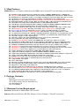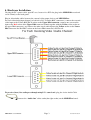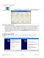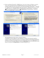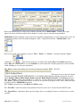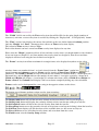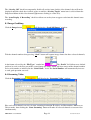
1
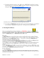
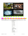
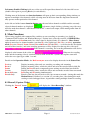
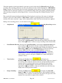
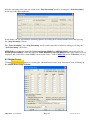
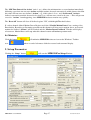
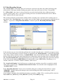
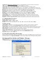
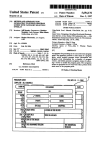
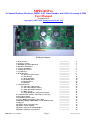
MPEGIOPro
4-Channel Realtime Hardware MPEG 2/4/1 Video Encoder with OSD, Streaming & SDK
User Manual
Version 1.0.7.2
Copyright © 2007~2011 Inventa Australia Pty Ltd
Table of Contents
1. Main Features
2. Package Contents
3. Minimum System Requirement
4. Hardware Installation
5. Software Installation
6. Starting the Software
7. User Interface
8. Main Functions
8.1 Record (Capture Video)
8.2 Text Overlay
8.3 Image Grabbing
8.4 Streaming Video
8.5 Motion Detect
8.6 Minimize
9. Setup Parameters
9.1 Video Recording Set-ups
9.2 Video Encoding Parameters
9.3 Audio Encoding Parameters
9.4 Other Set-ups
9.5 Setup During Recording and Streaming
10. Command Line Switches and Windows’ Messages
11. Drop Down Menu
12. Default Parameter Values
13. Create DVD from Captured Video Files
14. Running Multiple MPEGIOPro Cards Simultaneously
15. Support
Appendix 1: Keyboard Short-Cuts
Appendix 2: Mouse Clicking
Appendix 3: Drop-down Menu Hot Keys
Appendix 4: Hardware Specification
MPEGIOPro User Manual
Page 1
-------------------------------------------------------------------------------------------------------------------------------------------------------------------------------------------------------------------------------------------------------------------------------------------------------------------------------------------------------------------------------------------------------------------------------------------------------------------------------------------------------------------------------------------------------------------------------------------
2
2
2
3
4
7
7
9
9
11
14
14
15
17
17
18
20
21
21
21
21
22
22
23
23
23
23
24
24
24
Version 1.0.7.2
1. Main Features:
MPEGIOPro is a 4-Channel realtime hardware MPEG video encoder PCI card with many powerful features:
Realtime Capture 4-Channel superior-quality video/audio as MPEG2, MPEG4(H.263) or MPEG1 files
Live Stream All Channels’ Video/Audio to Any User-Defined TCP/IP Address in Unicast or Multicast mode
Realtime Preview all channels on PC’s screen with no visual delays between incoming video and screen video
All channels can capture/stream full D1 size (720X576 or 720X480 Pixel) video simultaneously
Support up to 4 Cards in One PC to Simultaneously Record & Stream 16-Channel Full D1-Size MPEG Video
Each Input Channel Can Record Video Only, Stream Video Only, or Record and Stream Simultaneously
All Channels’ Recording and Streaming Parameters Can Be Individually Defined
Wide-Range Capture/Streaming Data Rates 128Kbps~15Mbps for MPEG1, MPEG2 & MPEG4 formats
Various Video Capture/Streaming Frame Sizes from 176X120 to 720X576-Pixels
Multiple encoding Frame Rate supported: 23.976fps, 24 fps, 25fps, 29.97fps, 30fps, 50fps, 59.94fps, 60fps
Allow Multiple Aspect Ratio Encoding & Streaming: 4:3, 16:9(Wide-Screen), and Square PEL
Forever Video & Audio Sync during video preview, capture, streaming and in the recorded files
Video Capture Process Can Seamlessly Split Files either manually or at user-defined file size or time
No single frame lost during video splitting: combining all split files will form the exact original video stream
Instantly Start Video Capture at User’s Request (manually or programmatically) without lengthy delays
Start Video Capture as Video Signal Appears
Stop Video Capture after Video Signal Disappears for a period of user-defined time
Pause and Resume Recording without closing recording file
Realtime Overlay Text/Time onto Recorded MPEG File, Streamed Video and Previewed Video
Overlaid Text Can Have Different Size, Position, Duration, Black/White Colour, User-Definable Frames
Text Overlay Can Contain Any Text, or Current Encoding File Name, Video Bit Rate, MPEG Type, etc
Simultaneous Multi-line Text Overlay: max. 450 characters (15 rows X 30 columns) can be overlaid
Motion Detect is supported by on-board hardware for 9 separate regions on every input channel
Motion Detect can trigger recording, e-mail, audio-playback, image grabbing and on-screen text feedback
Motion Detect regions can be displayed on screen with different colours in all channels
Capture still images in various formats: JPEG, BMP, GIF, TIFF, and PNG
Capture/Stream DVD-Compliant or arbitrary MPEG2, MPEG4 or MPEG1 video files
Captured/Streamed DVD-Compliant files can be burnt to DVD movie immediately without re-compression
Capture Audio-Only MPEG files in small sizes without video components
Realtime on-screen preview video and audio always in sync with incoming video signal
PAL and NTSC video format are automatically detected and switched
Composite/BNC Video Input
Stereo Audio Input
Hardware-encoding chip built-in, low system resources needed: Pentium4 3GHz can record 16 Channels
Any-length Timer Recording and Date-Time-Scheduled Recording with user-definable file names
Support live colour change on incoming video
Automatic email-out of warning messages on signal loss, disk full and start/stop conditions
Recorded video file name can contain multiple fields inc. recording date, time, video length, video format, etc.
Loop Disk and Split File Number Reset functions to automatically free disk space on pre-set conditions
Work on Windows XP, Windows Vista and Windows 7 PCs with PCI slot
Include SDK with full C++ and VB source codes for Customized Software Development
2. Package Contents:
PCI Card
Multi-Input Video and Audio Connectors
One 4-Wire Audio Cable for Audio Preview
One Installation CD
One User Manual
3. Minimum System Requirement
Hardware: Pentium4 or AMD Athlon CPU based PC
Software: Microsoft Windows XP SP2, Windows Vista or Windows 7, DirectX 9 and above.
MPEGIOPro User Manual
Page 2
Version 1.0.7.2
4. Hardware Installation
Un-plug the PC’s power cable, open PC case, locate a free PCI slot, plug in the MPEGIOPro card and
screw it firmly to the back-panel.
Plug in video/audio cables between the external video output devices and MPEGIOPro:
For each video/audio input channel (as labeled A, B C, D on the BNC connectors), connect the external
video input to the Yellow BNC/RCA socket on the Upper DB9 connector, connect one stereo audio
input to the Red socket of the Upper DB9 connector (bound together with the Yellow video socket on
the upper DB9 connector), and connect the other stereo audio input to the Yellow socket on the Lower
DB9 connector (the Red BNC socket on the lower DB9 connector is NOT used):
To preview (hear) live audio pass-through using PC’s sound card, plug the 4-wire Audio Cable
between the “Audio Out” white socket(the right socket) on the MPEGIPro board:
MPEGIOPro User Manual
Page 3
Version 1.0.7.2
and the “CD-Audio In” or “Aux Audio In” socket on your sound card or
motherboard: Also the sound card’s “Recording Control” should select the “CD-Player” or “Aux” port:
.
Special Notes on audio preview:
1. Only the audio signal passing through the Upper DB9’s Red socket reaches the sound card’s CDIn or Aux-In (so can be heard), although both audio channels are recorded and/or streamed out.
2. Regardless the sound card input connection, audio connected to the upper and lower DB9
connectors’ sockets are always recorded and streamed out, i.e., as long as audio are connected to
upper/lower DB9 connectors, they will be captured by MPEGIOPro, independent of the
connection status of the “Audio Out” socket on MPEGIOPro card, and the sound card’s CD-In /
Aux-In sockets.
5. Software Installation
Software installation has two steps: device driver software installation and application software
installation.
1. After hardware installation, the Windows will inform that new hardware is found:
MPEGIOPro User Manual
Page 4
Version 1.0.7.2
2. Put the installation CD into PC’s CD/DVD drive, click “Next” button, let Windows search for
device driver specifically from the CD ROM. During the driver installation, ignore those
warnings claiming such as the device driver “has not passed Windows Logo testing…”(Win XP)
or “Windows can’t verify the publisher of this driver software” (Windows Vista or 7) etc, click
“Continue Anyway” (in Windows XP) or “Install this driver software anyway” (in Windows
Vista/7) to keep going, until the driver “Inventa MPEGIOPro Codec PCI Device” and driver
“Inventa Video RN5-4DB” are both installed:
After installation of the device drivers, check the Windows’
ControlPanel->System->Hardware->DeviceManager ->Sound, video and game controllers
category to make sure both device drivers are listed there without question mark or exclamation
mark(note each input video channel has one pair of device driver entry so one MPEGIOPro card
has 8 driver entries altogether. When more than one MPEGIOPro cards are installed these entry
numbers will equal to the MPEGIOPro card number multiplied by 8).
MPEGIOPro User Manual
Page 5
Version 1.0.7.2
When device drivers are installed properly, Windows will have a pop-up message box at the
lower right corner of the screen:
Please note:
After re-installing Windows on a PC with MPEGIOPro card remaining seated in PCI slot, eight
“Multimedia Controller/PCI Device” or similar lines will appear in the Windows’ ControlPannel>System->Hardware->DeviceManager window, preceded by a yellow question mark or
exclamation mark, since MS Windows will not(cannot) install their device driver software. All
these items will need “update driver” operation(right-mouse clicking then select “Update
driver…”) to install the proper driver software from the setup CD, before the MPEGIOPro card
and application software can be used properly. Alternatively, you can delete these questionmark/exclamation-mark preceded items(right-mouse click them then select “Uninstall”),
highlight the PC’s name in the DeviceManager window then select “Scan for hardware changes”:
,
then follow the same steps as at the start of this section to install device driver. Please note after
installing the application software (see next paragraph), the “SetupDrv.exe” program installed
into “Start->All Programs->Inventa->MPEGIOPro” group can also be used to automatically
set up all the 8 device drivers for the MPEGIOPro card.
MPEGIOPro User Manual
Page 6
Version 1.0.7.2
3. To install the application software, click “Next” on the “MPEGIOPro Setup Wizard” window --which normally starts up automatically after inserting the set-up CD, or will appear after doubleclicking the “Start.exe” software on the set-up CD:
,
then follow the on-screen instructions to install the application software.
4. Un-installing the MPEGIOPro application software can be done from Windows’ Control-Panel
or by running the “Uninstall.exe” program under “All Programs\Inventa\MPEGIOPro”
6. Starting the Software
will
After a successful application software installation, an “MPEGIOPro” shortcut icon
appear on the Windows’ desktop. Mouse double-clicking this icon will start the software. The software
can also be started from Window’s “Start->All Programs->Inventa->MPEGIOPro” group by selecting
either the “MPEGIOPro.exe” or “MPEGIOPro.exe No OSD” items
Please note:
(1).MPEGIOPro.exe start up will fail if other software using DirectX Overlay is running: Windows
MediaPlayer, Vlc.exe etc video play software are typical examples that use DirectX Overlay, exit these
programs before starting MPEGIOPro software ---- they can be re-started after MPEGIOPro has
successfully started and is displaying live video.
(2).Windows’ Hardware DirectDraw/Direct3D Acceleration must be enabled (run dxdiag.exe from
command-line to test and change) for MPEGIOPro to display live video properly.
(3).A VisualBasic written testing program called MPEGIOProVB.exe is also installed under the same
“Start->All Programs->Inventa->MPEGIOPro” group: this has a simple user interface and limited
functions.
(4).The “MPEGIOPro.exe No OSD” item under “Start->All Programs->Inventa->MPEGIOPro” group
is the same as MPEGIOPro.exe except command line switch –I is supplied which disables OSD display
but will launch the MPEGIOPro.exe program much faster.
7. User Interface
Once started, MPEGIOPro will expand on to full screen with multiple live preview video windows
sequentially arranged from left-right, top-down, with the first channel (Channel 0) at the top left and the
last channel at the bottom right:
MPEGIOPro User Manual
Page 7
Version 1.0.7.2
plus a row of function buttons at the bottom:
Right-mouse clicking any channel’s video area will also display a drop-down menu of selections, with the
first line indicating that channel’s current Operation Mode (Preview, Record, Encode, Stream -- see below):
MPEGIOPro User Manual
Page 8
Version 1.0.7.2
Left mouse Double-Clicking inside any video area will expand that channel of video into full screen
(double-click again or pressing Esc key to switch back).
Clicking most of the bottom row function buttons will open up their corresponding dialog windows to
operate on multiple video channels, while selecting most of the items from the drop-down menu will
only operate on that particular video channel.
At the left end of the bottom function button row, the total video channels available and the currently
. Left-mouse single clicking (selecting) any video area
selected channel number are displayed:
will also make that channel’s audio heard from the PC’s sound card output, while muting audio from all
other channels.
8. Main Functions
Unless being supplied with command line switches to start recording or streaming (see details in
“Command Line Switches and Window Messages” Section later), when first started, all MPEGIOPro
video channels are in Preview mode: live video signal is displayed only. If a channel’s “Show Status”
option is turned on, its channel number (start from 0), video signal type (Pal, Ntsc, or nOne), operation
mode (Preview, Record, Pause, Stream, Record&Stream, EncodeOnly --- see below for the description
on each of these modes), and some encoding parameters will be displayed at the top of its video area:
. If the channel is recording, the recording information will also be
displayed at the bottom of the video area:
. When not in recording
mode and the incoming video is switched between PAL and NTSC systems, the top line status will
reflect the new signal type within 1 second.
Details on the Operation Modes, the Red Acronyms are used to display the modes in the Status Line:
Preview:
Record:
Pause:
Stream:
Record&Stream:
EncodeOnly:
Display incoming video only, no encoding, recording and streaming
Display incoming video, encode the video and write the encoded data in disk file
During the Record mode, temporarily pause writing encoded data into disk file
Display incoming video, encode the video and stream the encoded data to network
Recording and Streaming simultaneously
Encode video but does not write to file, nor stream to network – during this mode the
Motion Detect (if defined, see section 8.5) can take place. Also during this mode
starting record can happen faster, in particular starting multiple-channel recording.
8.1 Record (Capture Video)
Clicking the “Record” button
MPEGIOPro User Manual
will display the “Start Recording” window:
Page 9
Version 1.0.7.2
Check the numbers of the input channels you want to record video then click Record button will start
recording. The recording parameters used for each channel are those defined through the “MPEGIOPro
Setup” window (See Its Section later for details). Depending on the setting, a file name prompt will pop
up either before or after the recording, or a pre-defined file name will be used silently. Warning dialogs
on overwriting existing files will not appear if the “Overwrite Existing Files Without Warning” box is
ticked.
The recorded file name including the full path will be displayed at the lower-left corner of each input
channel’s video area if that channel’s “Show Status” option is on (through menu selection or Setup
window). File name extension “.mpg” will be automatically added if this has not already been supplied.
During video recording process, several actions can be taken:
----
Stop Record:
Clicking the Stop button
displays Stop Recording window:
,
where multiple channels’ recording can be stopped altogether.
Selecting the “Stop Recording” item from the drop-down menu after rightmouse clicking a channel’s video area stops recording on that channel only.
----
Pause/Resume Record: Selecting the “Pause Recording” item from the drop-down menu will
pause writing video data into the current recording file but keep the file
open, selecting “Pause” item again will resume writing data into the same file.
Please Note: Although Inventa MPEGIO hardware decoder and many
software MPEG decoders such as the FREE MPEG2-decoder at
http://www.deskshare.com/download/mpeg2decoder.exe, CyberLink
PowerDVD etc, can often smoothly play back MPEG files with pauses,
some software decoders will pause if MPEG files contain short pauses
(usually < 30 sec).
----
Text Overlay:
will display the
Clicking the Overlay button
Overlay Setup window (see details in its Section below) where any channel’s
text overlay can be added or deleted on the fly, and the modified overlay
contents will be recorded into the current recording file immediately.
Selecting the “Overlay Toggle” item from the drop-down menu after
right-mouse clicking a channel’s video area will turn on or off all overlay
display and recording for that channel.
----
Image Grabbing:
Clicking the Image button
will display the Grab Still
Image window (see details in its Section below) where multiple channels’
still images can be captured, and their file name prefix, file types and serial
numbers (for consecutively captured files) defined.
MPEGIOPro User Manual
Page 10
Version 1.0.7.2
Selecting the “Grab Image” item from the drop-down menu after rightmouse clicking a channel’s video area will capture one still image for that
channel. Images grabbed this way will have the file name prefix and file
type as defined in the “Grab Still Image” window, and a separate serial
number starting from 1, which is independent of the serial number defined
in the “Grab Still Image” window, to be used in naming consecutively
captured files.
----
Video Streaming:
Clicking the Streaming button
will display the Streaming
Video window (see details in its Section below) where video streaming on
multiple channels can be started and stopped.
Selecting the “Start Streaming” or “Stop Streaming” item from the
drop-down menu after right-mouse clicking a channel’s video area will
turn on or off video streaming for that channel, using parameters defined in
the Streaming Video window.
----
Colour Adjustment: Instant Brightness, Contrast, Saturation and Hue can be adjusted, and
reflected in the recorded file and streamed video immediately, from within
the “MPEGIOPro Setup” window, see its section below.
----
Recording Timer:
Recording timer length can also be adjusted from within the
“MPEGIOPro Setup” window.
----
Split File:
File Splitting on a recording channel can be selected from its drop-down
menu’s “Split Recording File” item: once split, the current recording file
is closed, new file is being used to write recorded video, and the new file’s
name is displayed at the bottom line status area(if Show Status is On). The
MPEGIOPro split current recording file without stopping its on-board
encoding engine, therefore creates Seamlessly Split MPEG Files:
sequentially combing all split recording together (such as using DOS
command Copy /B) will create one MPEG file that equals to the un-split
recording on the same incoming video signal, without losing any binary
data --- no single frame or any information is lost.
----
Create Record Log,
Loop Disk,
Record Stop @ Signal Loss:
These can all be changed from within the MPEGIOPro Setup window,
see their corresponding details in the Setup window section below.
8.2 Text Overlay
Clinking the Overlay button
MPEGIOPro User Manual
will start up the “Overlay Setup” window:
Page 11
Version 1.0.7.2
.
Each video channel has its own overlay contents, therefore the “Channel Num.” Combox box at the
upper left corner will decide which video channel’s overlay setup is currently being modified.
MPEGIOPro allows multiple overlay items to be displayed simultaneously on each channel: these items are
sequentially numbered and selectable through the “No.:” combo box below the “Channel Num.” box:
.
Each overlay item can be defined as type of “Text”, “Timer”, or “Frame”, selectable from the “Type:”
combo box:
. All overlay items have to define their display Row and Column parameters,
where Row has values from 0 to 14, and Column has values from 0 to 29. Other parameters such as doublewidth, blinking etc are item type dependent.
The “Text” overlay items allow user to type text characters into the “Text” edit field:
. Each row of text on the video frame
can have maximum 30 single-width characters, or 15 double-width characters. Text overlay item can also
define Double-width, Double-height, Shadow, Border, Blink, Height, Duration, and Colour parameters.
The valid “Height” values range from 0 to 71: values 0 ~ 17 have the same size which is the default setting.
The “Dura.” parameter defines how many seconds an overlay item will appear on the video, from the time it
is displayed by the MPEGIOPro software.
The “Colour” parameter has only Black and White values.
The “Text Hex” combo box allows non-printable character values to be selected by their ASCII values.
The “Special Text” combo box allows special strings such as recording file name or video bit rate etc to be
overlaid:
MPEGIOPro User Manual
Page 12
Version 1.0.7.2
The “Width” field is not used by the Text overlay item, but will be filled as the string length (number of
characters) each time a text overlay item is overlaid by clicking the “Display/Add”, or ‘DisplayOnly” button.
The “Time” overlay item displays the current date and time at the user defined row and column position.
Only the “Height” and “Dura.” Parameters have effects on Time overlay item display.
The colour for Time overlay is always White.
Each video channel can have at most one Time overlay item displayed at any time.
Please note the “Height” parameter affects all text and time overlay items’ text height within a video channel:
if one text item uses height 33, and later another time overlay item uses height 19, then all text and time
displayed will have been using the later-defined text height 19.
The “Frame” overlay item allows maximum 4 rectangle frames to be displayed anywhere on the video
.
window: frames are numbered from 1 to 4 and selected from the “Frame Num:” combo box:
Apart from row and column parameters, Frame overlay item has Colour, Dura. Width and Height
parameters. The Width for Frame overlay item indicates the number of columns minus 1 a frame spans on a
horizontal line, and the Height indicates the number of rows minus 1 it occupies vertically: a frame of 0
Width and 0 Height will display a 1 row height X 1 column wide frame, while a Width 29 and Height 14
Frame at Row 0 and Column 0 will display a full screen frame completely hiding any video in behind.
Frames can be used as background for a text string in the opposite colour, such as these:
.
The bottom row of buttons perform various overlay item operations:
The Display/Add button will add the currently defined overlay item into its item list and display it
The Display Only button will display the currently defined overlay item but not adding it to item list
The Erase/Delete button will delete the selected Overlay Item from the item list
The Erase/Keep button erases the currently selected overlay from screen but not deleting it from the item list
The Full Test button displays all 256 characters of the available font as a full screen overlay test
The Erase All button erases all defined overlay items and erase them from the screen
The Finish button exits the Overlay Setup window.
MPEGIOPro User Manual
Page 13
Version 1.0.7.2
The “Overlay Off” check box temporarily disable all overlay items for this video channel: they will not be
displayed until this check box is ticked again, or until the “Overlay Toggle” menu item is selected from the
Drop-down Menu of this video channel(right-mouse clicking its video area).
The “Auto Display @ Recording” check box allows an overlay item to appear each time this channel starts
recording.
8.3 Image Grabbing:
Click the Image button
will display the “Grab Still Image” window:
Tick the channel numbers then pressing “Grab” button will capture image frames for those selected channels,
. The “Prefix” field allows user-defined
in the format selected by the “File Type:” combo box:
prefix to be used as the first part of the created image file name, which will also consist of the channel number
and a serial number as indicated in the “Serial Num.:” field. The Serial Number will automatically increase
as each grab operation succeeds.
8.4 Streaming Video:
Click the Streaming button
will display the “Streaming Video” window:
Here each video channel can select its own streaming destination IP address and Port number, Multicast or
Unicast mode, then clicking the “Start Streaming” button will make all selected channels to stream video
simultaneously.
MPEGIOPro User Manual
Page 14
Version 1.0.7.2
After the streaming starts, you can switch to the “Stop Streaming” mode by clearing the “Start Streaming”
check box in the upper right area:
In this mode you can stop multiple streaming channels by ticking their channel number boxes then pressing
the “Stop Streaming” button.
The “Start Streaming” and “Stop Streaming” modes can be manually switched by ticking or clearing the
“Start Streaming” check box.
MPEGIOPro streams out unmodified Program Stream MPEG2 or MPEG4 (H.263) video and audio, or
System Stream MPEG1 video and audio, or Audio Elementary Stream MPEG2 audio, that can be received,
displayed and recorded by various MPEG video stream client -- such as MPEGIO card or VideoLan (vlc.exe).
8.5 Motion Detect:
Clicking
button, or selecting the “Motion Detect Setup” drop down menu item, will bring up
the Motion Detect Setup Window:
MPEGIOPro User Manual
Page 15
Version 1.0.7.2
MPEGIOPro handles Motion Detect through its on-board hardware. For each input video channel, up to 9
separate areas can be set up as Motion Detect Region. Each region can be as small as 16 X 16 pixels, or as
big as the full video frame (720X576-pixel PAL, 720X480-Pixel NTSC). Each region’s upper left coordinates
(X, Y) and width/height values must be multiples of 16. Each defined region also has a user-definable
“Threshold”, indicating the sensitivity level MPEGIOPro hardware uses to report motion detect: low
“threshold” value indicates high sensitivity --- small movement will be reported as motion detected, and high
“threshold” value indicates low sensitivity --- bigger movement is needed to report having motion detected.
Valid “threshold” values are from 1 to 65535, different regions can define different “threshold” values.
Once the Motion Detect Regions X/Y, Width/Height and Threshold are defined, and the “Enable Motion
Detect on This Channel” Box is ticked, clicking the Apply button to make them effective – if clicking Exit
before clicking Apply will lose the definition made.
Ticking the “Show Regions on Video” box will display the defined regions on the channel’s video window –
use the “Show Colour” button to define the colour used to draw regions.
MPEGIOPro allows several “Actions” to be happen in response to motion detected during recording:
(1) Start Recording: video from the time Motion Detect happens will be written into a file, the file
name is formed according to the Setup Window. Existing file with the same name will be
overwritten without warning.
(2) Write Motion Detect Info to File: text in the form of time, channel, region, are recorded, such as:
2008-4-9 15:07:26 Ch1 R1:9A, R2:178 --- indicating
Channel 1, Region 1 has motion vector sum 0x009A
Channel 1, Region 2 has motion vector sum 0x0178
The “Motion Vector Sum” for each region recorded indicate roughly the volume of motion
detected in that region: larger value indicates more motion detected.
The text file name used to record motion detect info. is formed as:
MPEGIOPro_ChannelNumber_MD_info_date_time.txt, such as:
“MPEGIOPro_ch01_MD_info_2008-4-9_15-7-25.txt” for Motion Detect Info file on channel 1,
which is saved in the channel’s video recording folder as defined in the Setup Window.
(3) Grab Still Image: JPEG file is grabbed at the time motion was detected, together with any OSD
text if defined, again in the video recording folder of the channel. The file name is formed as:
MPEGIOPro_ChannelNumber_MD_Still_date_time.jpg, such as:
MPEGIOPro_ch1_MD_Still_2008-4-9-15-7-26.jpg
(4) Send e-mail to address defined on screen: such as [email protected]. Note this e-mail address
is the same as defined in the Setup Window(See Section 9 below) as “Warning E-Mail Address”.
(5) Play Audio File: file name can be defined on screen, such as C:\Windows\Media\notify.wav
In addition to these Actions, a “Motion Detect Feedback” Window can be opened from the Drop Down
Menu, that will dynamically reflect the current Motion Detect activities happening on all channels:
MPEGIOPro User Manual
Page 16
Version 1.0.7.2
The “MD Time Interval for Action” (min. 1 sec.) defines the minimum time a second motion immediately
following a previous one can cause Action: multiple motions detected consecutively within shorter time than
this value will not cause any defined “Action”: e.g., if this value is 2 sec., and “Send e-mail” Action is
defined, consecutive motions detected in less than 2 sec. will not cause e-mail to be sent --- This will prevent
excessive “Actions” from happening, since MPEGIOPro detects motion very quickly.
The “Reset All” button will clear all defined regions’ X/Y, width/height/Threshold values.
If a video channel defined Motion Detect Regions and ticked “Enable Motion Detect” box, starting video
EncodeOnly, Recording or Streaming operation on this channel will also start its motion detect: on detected
motions the defined “Actions” will be invoked and the “Motion Detect Feedback” Window will display
relevant text. Motion Detect will stop when this channel returns to Preview operation mode.
8.6 Minimize:
will minimize MPEGIOPro into an icon on the Windows’ Taskbar
Click this button
area:
, where it can be left-mouse clicked to restore back to normal display.
9. Set-up Parameters
Clicking the “Setup” button
MPEGIOPro User Manual
will start the MPEGIOPro Setup Window:
Page 17
Version 1.0.7.2
9.1 Video Recording Set-ups
The “Current Path” is the folder where all recorded or converted video files and grabbed still image files
will be placed. Left-mouse double-clicking any path or drive name will select it as new “Current Path”.
If a “Mirror Disk” drive letter is selected (must be one of the fixed hard disk drives different from the
current recording path’s drive), each video recording will create an identical mirrored file on the “Mirror
Disk” with the same file name and path.
The recorded video files can be named each time before recording starts, each time after recording ends, or
pre-named. If the “Pre-Named as:” box is ticked, you can either supply a fixed name typed in the field next to
“Text->:”, or press the “Setup File Name Fields->” button to open the “Recording File Name Fields”
window:
Recording File Name Fields Window
In this window you can select fields that will form the recorded video file name: each field can appear at most
once, at least one field must be selected. Fields are separated by the “Field Separator” as shown in the middle
of the dialog window. Double-click any “Available Fields” item will add that field into the “Selected Fields”
list-box, where the fields can be moved up and down to form their relative positions in the recorded file name.
The “User Pre-Named Text” field will contain any text typed in the text box in the lower part of the window.
If this field contains nothing, MPEGIOPro will automatically assign “MPEGIOPro_Chan#.mpg” as its
contents, where the ‘#’ will be a channel’s number, such as 0, or 3.
The “Auto Serial Number” field will increase its value by one each time a new file is recorded, its initial
value can be assigned in the “Automatic Start Serial No. from:” box when this item is highlighted in the
“Available Fields” list box.
If the “Recording Duration” field is selected, initially during the recording this field will have content
“0H00M00S”, and this content will change to the actual recording time when recording stops, such as
“0H30M00S”(30Min).
As an example, using the selected fields in the above screenshot, a 3-Min 15-Sec. recording will be named as:
MyChan0Record_20070130_164720_0H03M15S_DVD_Video7000Kbps.mpg
MPEGIOPro User Manual
Page 18
Version 1.0.7.2
Before the recording, if the named file already exists, a warning dialog will appear before overwriting the file.
Video recording can have a Timer, as indicated by the “Timer:” field. Zero value timer means endless
recording until the “Stop” button is clicked, or Stop Recording menu item is selected, or MPEGIOPro
software is ended. Once recording has started, the recording timer can still be adjusted from the vertical
.
scrollbar control next to the timer field:
During the recording process, new video files can be created (Split) without stopping the recording, by either
specifying a file size limit (the “Split Recording File at File Size of Every:” tick box), a recording time limit
(the “Split Recording File at Recording Time:” tick box), or manually selecting the “Split Recording File”
item from that channel’s drop down menu. If the box “Reset at Split” is ticked, a hardware reset to the MPEG
encoding IC will be made each time a file split happens: doing so can reduce possible hardware encoding errors
although hardware reset to MPEG encoding IC will interrupt the encoding process for about 1 sec. The check
box “SplitOver1” means the same recording file will be overwritten repeatedly each time a file split happens
thus no newly named split file will be created; this is for testing purpose only.
Since each DVD/CD disk only has limited capacity, splitting recording file is very useful to spread long video
recording across multiple files for multiple DVD/CD burning without interrupting the recording process. The
split-video files will be named after the first recording file name with consecutive numerical numbers: if the first
recording file is mpeg.mpg, the split files will be mpeg00001.mpg, mpeg 00002.mpg, etc., with an everincreasing 5-digit numerical number appended to the first file name. However, if the box “Reset Split File
Number When Reaching” is checked and the edit box to its right has a value bigger than 0, this 5-digit
numerical number will repeat between 0 and this value. For example, if this value is set to 666 (as in the Setup
Window screenshot two pages earlier), the split files created will be mpeg.mpg, mpeg0001.mpg,
mpeg0002.mpg, …, mpeg0665.mpg, mpeg0666.mpg, repeatedly. When the split recording is closing file
mpeg0666.mpg (the last file in the sequence), the next split file name to be used will again be mpeg.mpg (the
first file in the sequence), and the video previously recorded in this file will be overwritten. Using such a
repeated split file name scheme will create a fixed sequence of recording files and prevent filling-up disk space.
Please note, if the “Recording File Name Fields” defined contains “Recording Date”, “Recording
Time”, “Recording Duration”, or “Auto Serial Number”, then the “Reset Split File Number When
Reaching:” box will be cleared / disabled and its number will be set to zero, since any of these fields
will make the recording file names become dynamically changing during the recording process.
Stopping the video recording can be either manual (default), or automatic if video signal disappears for a
certain period of time, by checking the “Record Stop @ Signal Loss” box and supplying signal loss time:
.
Please note, the video recording to hard disk only starts when video signal is available, that is, after
video recording button is pressed or timer is started, if there is no video signal, the recording to hard disk
will wait until the video signal appears. This is useful if the video tape inside VCR or Camera has unrecorded section at the start: you can start the tape playing early and be assured that the start of the video
contents on the tape will always be accurately recorded by MPEGIOPro at the start of the MPEG file.
The “Create Log” check box indicates if a file named “MPEGIOPro.log” will be created and maintained under
the system-drive folder (usually C:\) for Windows XP, or under the SYSTEM-DRIVE\Users\Public folder for
Windows Vista/7, to log every recorded video file name, length, encoding type, possible error, etc. This
“MPEGIOPro.log” file will be used by the “Loop Disk” function in the following fashion:
MPEGIOPro User Manual
Page 19
Version 1.0.7.2
If the “Loop Disk” box is checked, and the current hard disk’s free space becomes lower than 50Mbytes during
the recording time, MPEGIOPro will automatically delete the oldest recording file as remembered by the
“MPEGIOPro.log” file to increase free space (If a “Mirror Disk” is selected, the same oldest files on the
mirrored disk will also be deleted). To automatically increase free space as hard disk becomes full, tick the
“Create Log” box together with “Loop Disk” box, so that all currently being recorded file names can be
remembered by MPEGIOPro.log file that will be used for automatic deletion when free space becomes low.
The “Black Screen Recording” check box indicates if total blackness will be recorded in the file to replace all
video frames. Using this option could record a video file with very low video bit rate but normal sound, useful
for creating a DVD disk that has long hours of audio but only black screen video.
The “Ignore Encoding Error” check box indicates if to continue encoding during MPEG recording (to file)
when an encoding hardware error happens: ticking this box means the program will automatically recover from a
hardware encoding error and continue recording encoded data to the same MPEG file without interruption,
clearing this box means the program will display a dialog box asking the user to select continue or stop encoding
if a hardware encoding error happens.
can be clicked to show the MPEGIOPro Recording Scheduler:
The Scheduler button
MPEGIOPro Recording Scheduler Window
Adding scheduled recording will cause MPEGIOPro software to start recording at those times
accordingly. Press the “Modify” button after changing an existing schedule’s content.
If one of the conditions (Program Start / Exit etc) under the “Send Warning E-mail When:” is ticked and
an e-mail address supplied, MPEGIOPro will automatically send e-mail when the ticked condition happens.
Note some e-mail software needs to be set up to allow automatic sending e-mail by other software: e.g. in
Outlook Express 6, the “Warn me when other application try to send e-mail as me” box under the
“Tools->Options->Security” must be cleared or a warning box will always pop up before sending e-mails.
9.2 Video Encoding Parameters
Video Standard(PAL or NTSC): Automatically Selected by MPEGIOPro Software, do not change
Type: DVD, VCD, SVCD, MPEG1/2/4. Use DVD if burning DVD movie disk is required.
Stream: Selectable from System Stream (MPEG1), Program Stream(MPEG2/4) and Audio Elementry
MPEGIOPro User Manual
Page 20
Version 1.0.7.2
VOB Format: Must Always Be Ticked, unless creating DVD files for Ulead software to load faster
CBR: Constant Bit Rate(box checked) or Variable Bit Rate(box cleared)
Closed GOP: The encoded Group-of-Picture is closed(do not use previous frames) or not
GOP N value: number of frames in a GOP, between 1 ~ 256. GOP N = 1 and GOP M = 0: I-Frame only
GOP M value: number of B & P frames in a BP frame loop within a GOP, between 0~3, 0 = I-frame only
Bad Sync: Detect and process bad timing signal for old VHS tapes played through VCR
Frame-Size (Resolution): selectable in pixels, inc. 704X576(PAL), 704X480(NTSC) etc
Frame-Rate: encoded Video Frames per Sec., default to 25 fps for PAL, 29.97 fps for NTSC
Bit Rates: selectable in Bit-Per-Second(bps) unit, ranges between 128Kbps to 15Mbps
Aspect Ratio: 4:3,16:9, or Square. This changes the encoded pixels’ shape, not frame-size.
Vertical Mask (under “Video Recording Start Position Mask”): remove lines at top of video frame
Horizontal Mask (under “Video Recording Start Position Mask”): remove pixels at left of video line.
Brightness, Contrast, Saturation, Hue: Chroma and Luminance characteristics of the encoded video
9.3 Audio Encoding Parameters
Format: MPEG1 Layer 2, or AC3
Sampling Rate: 32KHz, 44.1KHz, 48KHz
Bit Rate: 32K, 48K, 56K, 64K, 80K, 96K, 112K, 128K, 160K, 192K, 224K, 256K, 320K, 384Kbps
9.4 Other Set-ups
Channel Num. Combo Box: select which video channel’s parameters will be displayed / changed
Password Field: if set then starting Setup Window will need to supply the correct password
Audio Volume: Only controls the channel’s audio preview volume, will not affect encoded audio volume
Show Status Box: If display status lines in the channel’s video area: status won’t be recorded/streamed
Status Colour: Colour used to display status lines for this channel
Copy to All Channels Button: copy this channel’s set up values to all other channels
Overlay: Same as pressing the Overlay button from the main MPEGIOPro window
SAA7134: Debug use only, do not enter
9.5 Setup During Recording and Streaming
During recording or streaming, most set-up parameters cannot change: the Setup window will disable their
fields and buttons, and “Copy to All Channels” will not copy settings to any recording/streaming channel.
10. Command Line Switches and Windows’ Messages
MPEGIOPro.exe can be started with some command line switches, such as:
“C:\Program Files\Inventa\MPEGIOPro\MPEGIOPro.exe" –H –R0 –S0 –R2 –S3
MPEGIOPro User Manual
Page 21
Version 1.0.7.2
Please Note:
1: the # in –R#, -S# is for digits 0, 1, 2, etc representing video channels
2. the “-U” switch is only for not to load some predefined OSD user fonts, so that software can start faster
3. the –F# indicates how often the software will refresh video overlay surface, default # is 30 ms.
Note refreshing video overlay surface is only necessary for some graphics card(such as Nvidea GeForce
7X00, 8X00) that will not display live video smoothly without constantly doing so(usually at 30ms per
refresh). If your PC’s graphics card(shown at the lower left corner of the Setup Window) is not those
brand/model with known live video overlay problems, you can safely supply –F0 to disable refreshing to
save some CPU cycles. The value used as the refreshing time (the # in –F#) is displayed as “ReFre” at
the mid-bottom line on the Setup Window.
4.the -I switch will disable OSD display (OSD setup is still available) but speed up the program start-up.
MPEGIOPro can receive user-defined Windows messages from MPEGIOPro SDK or other programs:
WM_MPEGIOPRO_START_RECORD
WM_MPEGIOPRO_STOP_RECORD
WM_MPEGIOPRO_START_STREAM
WM_MPEGIOPRO_STOP_STREAM
WM_MPEGIOPRO_MINIMIZE
WM_MPEGIOPRO_SPLIT_RECORD
WM_MPEGIOPRO_GRAB_IMAGE
WM_MPEGIOPRO_RESTART_CHANNEL
WM_MPEGIOPRO_FLIP
WM_MPEGIOPRO_QUIT
WM_MPEGIOPRO_PAUSE_RESUME
WM_MPEGIOPRO_START_ENCODE_ONLY
WM_MPEGIOPRO_STOP_ENCODE_ONLY
WM_MPEGIOPRO_ENCODE_ERR
(WM_USER + 10) // WParam indicates chan#
(WM_USER + 11) // WParam indicates chan#
(WM_USER + 12) // WParam indicates chan#
(WM_USER + 13) // WParam indicates chan#
(WM_USER + 14) // Window is minimized
(WM_USER + 15) // WParam indicates chan#
(WM_USER + 17) // WParam indicates chan#
(WM_USER + 18) // WParam indicates chan#
(WM_USER + 19) // WParam indicates chan#
(WM_USER + 20) // Quit MPEGIOPro software
(WM_USER + 21) // Pause/Resume recording Toggle
(WM_USER + 22) // WParam indicates chan#
(WM_USER + 23) // WParam indicates chan#
(WM_USER + 24) // WParam is chan#: Encoding error happened
Note “WM_USER” is normally defined as 0x0400 by MS Windows SDK
11. Drop Down Menu
Right-Mouse click any channel’s video area displays the drop-down menu, most of the items there have
been explained earlier regarding each channel’s recording, streaming, overlay, status, etc. Other items are:
Reset Channel: Hardware-reset a video channel, can be used in extreme situation, such as when channel
had bad signal, encoding error happened: cannot use when channel is recording/streaming
Flip: flip the on-screen video display 180-degree horizontally, will not affect recorded video.
Start EncodeOnly: Start encoding video, without writing the encoded data to file or streaming them to
network, the main purpose of entering this mode is to respond to Motion Detect, and/or to speed up
subsequent Start Record operation (in particular when Starting Record on multiple channels).
12. Default Parameter Values
Each time on exit, MPEGIOPro saves its start-up parameter values in file “MPEGIOPro.INI” under
SYSTEM-DRIVE folder (normally C:\) for Windows XP, or under SYSTEM-DRIVE \Users\Public folder for
Windows Vista/7. If MPEGIOPro.INI file does not exist, or if holding down the Ctrl key while left-mouse
double-clicking the MPEGIOPro icon, the software will start again using the default values, as listed here:
Current Recording Path: System-Drive:\ for WinXP, System-Drive\Users\Public\ for WinVista or Win7.
Mirror Disk: None
Recording Timer: 0 (no timer)
Name Recording File: Prompt before recording
Split Recording File at File Size: 0(no split)
Split Recording File at Recording Time: 0(no split)
Reset at Split: No
Reset Split Recording File Number: No
SplitOver1: No
Recording Stop @ Signal Loss: Not Used
MPEGIOPro User Manual
Page 22
Version 1.0.7.2
Video Encoding Parameters: DVD, 704X576-Pixels for PAL, 704X480-Pixels for NTSC, 4:3 Aspect Ratio
VOB Format: Yes
CBR (Constant Bit Rate) Encoding: Yes
Max. Encoding Bit Rate: 7Mbps
Average Encoding Bit Rate: 6Mbps
Closed GOP: No
GOP N Value: 15
GOP M Value: 3
Bad Sync Detect: No
Video Encoding Frame Rate: 25 fps for PAL, 29.97 fps for NTSC
Audio Encoding Parameters: MPEG1Layer2, 48KHz, 192Kbps
Vertical Mask: 0
Horizontal Mask: 0
Show Status: Yes
Overlay Items: None Defined
Streaming IP Address for Multicast: 239.255.0.0, Port 1234 for Channel 0, Port 1235 for Channel 1, etc
Streaming IP Address for Unicast: 10.0.0.3, Port 1234 for Channel 0, Port 1235 for Channel 1, etc
Send Warning e-mail: No for all conditions
Create Log(use MPEGIOPro.log to log all recordings): No
Loop Disk(Delete Oldest Files Ever Recorded When Free Space Is Lower Than 50 MB): No
Black Screen Recording: No
Ignore Encoding Error: No
Password for Setup Window: None
Motion Detect: Not on
13. Create DVD from Captured Video Files
To create DVD movie disks from video files recorded by MPEGIOPro, a DVD Authoring Software,
such as TMPGEnc DVD Author, NeroPro, Ulead DVDMovieFactory, Adobe Encore, etc, is needed.
DVD menus, buttons, chapter points etc can be created from within the DVD authoring software.
14. Running Multiple MPEGIOPro Cards Simultaneously
Up to 4 MPEGIOPro PCI cards can operate in one PC simultaneously: MPEGIOPro software will
automatically recognise how many total channels are available in a PC by querying the successfully
installed device drivers of all MPEGIOPro cards, and display their video channels correctly on the screen.
The only extra connection needed for multiple MPEGIOPro cards is to link their audio preview sockets
use the bundled 4-wire CD-Audio connection cables
to link the
together in tandem:
1st card’s “Audio Out” socket (the right white socket on the top when viewing the front side of the card with
back-panel bracket on the left) to the “Audio In” socket (immediately to the left of the “Audio Out” socket) of
the 2nd MPEGIOPro card, the 2nd card’s “Audio Out” socket to the 3rd card’s “Audio In” socket, the 3rd
card’s “Audio Out” socket to the 4th card’s “Audio In” socket, and the 4th card’s “Audio Out” link to Sound
Card “CD-In” or “Aux In” socket. Any MPEGIOPro card can be used as 1st or last, no particular order is
assumed.
15. Support
Technical support is at [email protected].
Appendix 1: Keyboard Short-Cuts
E:
I:
M:
O:
Q:
Streaming Video Window
Grab Still-Image Window
Motion Detect Setup
Overlay Setup Window
Quit MPEGIOPro Software
MPEGIOPro User Manual
Page 23
Version 1.0.7.2
R:
S:
U:
Z:
Esc:
Video Recording Window
Stop Recording Window
Set-up Window
Minimize MPEGIOPro Window
Restore from Single-Channel Video Full Screen Mode, or Quit Software
Appendix 2: Mouse Clicking
Left Mouse Single Click:
Left Mouse Double Click:
Right Mouse Single Click:
Select current video channel and make its audio preview heard
Full Screen Mode for the current video channel or exit full screen mode
Display Drop-down Menu for one Video Channel.
Appendix 3: Drop-down Menu Hot Keys
A:
C:
D:
E:
F:
I:
L:
M:
N:
O:
P:
Q:
R:
S:
U:
W:
Z:
About MPEGIOPro
Reset This Channel
Motion Detect Feedback
Streaming Start or Stop on this channel
Flip Video Preview Horizontally
Grab One Still Image from this channel
Split Recording File
Motion Detect Setup
Start/Stop EncodeOnly operation
Overlay On / Off Toggle
Pause / Resume Recording (into current file)
Quit MPEGIOPro Software
Start Recording on this channel
Stop Recording on this channel
Display Setup Window
Show/Hide Status
Minimize MPEGIOPro Window
Appendix 4: MPEGIOPro Hardware Specification
Encode Video Formats: MPEG-1, MPEG-2 MP@ML, MPEG-4 Simple Profile@L1,L2 & L3, with extensions to full-D1,H.263. I, IP, IBP,
IBBP Frames. PES & ES.
Constant and Variable Bit Rate Encoding User Selectable
Video 4:2:2 to 4:2:0 conversion
Video Inverse telecine(3:2 pulldown)
Video frame rates: 23.976fps, 24 fps, 25fps, 29.97fps, 30fps, 50fps, 59.94fps, 60fps
Video bits-rate from 128Kb/s~15Mb/s for MPEG1, MPEG2, and MPEG4(H.263)
Video resolution pixels PAL:176X144, 352X288, 480X576, 704X576, 720X576. NTSC:176X120, 352X240, 480X480, 704X480, 720X480
Video Encoding Aspect Ratio: 4:3, 16:9, Square PEL
Audio formats: MPEG-1 Layer II, AC3/Dolby 5.1,
Audio sample rates: 16k, 22.5K, 24K, 32K, 44.1K, 48KHzAudio bit rates: 32Kbps ~ 384Kbps
PCI Bus v2.1 Compliance
Video Input Channels: 4 X Composite (BNC)
Audio Input Channels: 4 X Stereo Left and Right BNC
Physical Dimension: 239mm(Length) X 105mm(Height --- not including PCI Connectors of about 7mm)
MPEGIOPro User Manual
Page 24
Version 1.0.7.2