1
MPEGIO2
PCI-E Dual-Channel MPEG2/4/1 Encoder/Decoder with IP Streaming, Colour Overlay, Digital I/O and Comprehensive SDK
Application Software Manual
Version 1.0.2
Copyright © 2012 Inventa Australia Pty Ltd
Table of Contents
1.
2.
3.
4.
5.
-------------------------------------------------------------------------------------------------------------------------------------------------------------------------------------------------------------------------------------------------------------------------------------------------------------------------------------------------------------------------------------------------------------------------------------------------------------------------------------------------------------------------------------------------------------------------------------------------------------------------------------------------------------------------------------------------------------------------------------------------------------------------------------------------------------------------------------------------------------------------------------------------------------------------------------------------------------
2
3
3
3
3
3
4
5
5
6
6
6
7
7
7
8
9
14
17
20
20
21
13. MPEG Encoding Parameters
-------------------------------------------
24
14. Record Video
-- Setup Recording
-- Start/Stop Recording
15. Stream Video
16. Capture Still Images
17. Playback MPEG Video (Decoding)
18. Digital Input/Output Pins
19. Other Drop-down Menu Selections
20. Command Line Parameters
21. Default Parameter Values
22. Hotkeys
23. Special Applications
24. Technical Discussions
25. MPEGIO2 Hardware Specifications
-------------------------------------------------------------------------------------------------------------------------------------------------------------------------------------------------------------------------------------------------------------------------------------------------------------------------------------------------------------------------------------------------------------------------------------------------------------------------------------------------------------------------------------------------------------------------------------------------------------
27
27
29
29
31
33
35
37
37
38
41
42
43
44
6.
7.
8.
9.
10.
11.
12.
Main Features & Functions
Package Contents
Minimum System Requirement
Hardware Installation
Software Installation
-- Device Driver Software Installation
-- Application Software Installation
Device Architecture
User Interface
-Control Window
-Video Window
-Drop-down Menu
-Taskbar Icon
-Total Channel Number
-Multiple MPEGIO2 Cards
Breakout Box Sockets
Video Input/Output
Audio Input/Output
Video Preview & System Setup
Overlay Text and Graphics on Video
-Overlay Item Management
-Overlay Item Types
MPEGIO2 Application Software Manual
Page 1
Ver. 1.0.2
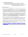
1. Main Features and Functions
MPEGIO2 is a dual-channel, multi-I/O, colour Overlay and hardware MPEG 2/4/1 encoding + decoding
PCI-Express Card with many powerful features:
--- Real-time encode MPEG2, MPEG4 and MPEG1 video using on-board hardware compression chipset
--- Real-time decode MPEG2/4/1 video on PC screen and external TV simultaneously using on-board chip
--- 2 Channels per MPEGIO2 Card, each capable of Encoding & Decoding, maximum 16 channels per PC
--- Real-time Encode 128Kbps to 15Mbps MPEG Video per Channel with Stereo Audio
--- Overlay Colour Graphics & Text Simultaneously on Encoded MPEG Video and external TV Screen
--- Overlay colour text, graphics, timer/counter, rectangle and box with alpha transparency and blinking
--- Multiple input video as picture-in-picture, picture-by-picture for preview, encode, stream and TV output
--- Each channel has 4 sub-windows to display video in different sizes, positions, and colour parameters
--- Live preview multi-channel video on PC screen inside re-sizable / movable window or full screen
--- Simultaneous Video Input/Output per Channel on 2xRCA, 1xSVideo In + 2xRCA/SVideo Out Sockets
--- 2 Stereo Audio Input & Output Sockets per Channel, Each Audio Input has its own gain control
--- 2 Audio Input, MPEG Decoding Audio and Audio from Matching Channel can be mixed to be encoded
--- 4 Digital I/O Sockets per Channel for real-time control to external devices, digital input is via interrupt
--- Perfect Audio/Video Synchronization maintained on video preview, recording and streaming
--- Seamlessly Split Recorded MPEG files manually or automatically at fixed time or length in real-time
--- Record Video using timer or calendar scheduler with daily or weekly repeat options
--- Real-time Stream Video over IP Network multi-cast or uni-cast independent of file recording status
--- Real-time Flip Input Video horizontally or vertically and Enlarge Video from any point (2-times zoom)
--- PAL and NTSC encoding at various sizes from720X576, 720X480, down to 176X144-Pixels
--- PAL/NTSC Conversion: Record, Stream, Preview and Output PAL input as NTSC, or NTSC as PAL
--- Program Stream (PS) or Transport Stream (TS) MPEG Video can be Encoded and Decoded
--- Selectable encoding parameters inc. bit-rate, frame rate, frame size, GOP structure, sampling rate, etc.
--- Various Encoding Aspect-ratio supported inc. 4:3, 16:9, 1:1 and 2.21:1
--- Capture Still Images as bmp, jpg, gif, tiff, and png format at 720X576/480-Pixel independent of record
--- Live recording status can be displayed inside video frame with user-definable colour, font and position
--- Min. CPU Usage maintained on multiple channel video preview, encoding, decoding and streaming
--- Comprehensive Software Development Kit with C++, VB, C++.Net, C#.Net, VB.Net Source Codes
--- Device Driver, Application Software with Source Code and SDK for Windows XP, Windows 7 or above
MPEGIO2 Application Software Manual
Page 2
Ver. 1.0.2
2. Package Contents
1XPCI-Express Card, full Software with SDK, video/audio Breakout Box and Connection Cable.
3. Minimum System Requirement
Hardware: Intel/AMD CPU PC with 1XPCI-Express Slot, 2GB RAM, 512MB Graphics card and audio.
Software: MS Windows7 or XP SP2, DirectX9 on Windows XP, Direct3D9 on Windows 7 or above.
Note 1: PC’s Graphics Card must install its latest device driver, otherwise Video Preview might fail.
Note 2: Only 32-bit Windows XP, Windows7/8 are supported, 64-bit Windows are not supported.
4. Hardware Installation
With PC power off, plug MPEGIO2 PCIe card into a PCI-Express slot, screw the back metal bracket
onto PC’s rear rack. Connect the 68-pin SCSI cable between the back-socket on the MPEGIO2 card
and the Breakout Box, connect external video/audio device’s video/audio output sockets to the input
sockets on the Breakout Box. If needed, VCR or TV can be connected to the TV Output sockets on the
Breakout Box to real-time display input video with colour overlay like a video overlay device, or to
real-time output multiple input video window placements like a video multiplexer device.
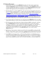
5. Software Installation
Software installation includes Device Driver and MPEGIO2.exe application, either one can install first.
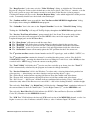
Device Driver Software Installation
When PC is powered on with the MPEGIO2 card plugged in, MS Windows will inform new device is
found and ask for the location of device driver: indicate to Windows the device driver software is
located either at the installed application software folder (C:\Program Files\Inventa\MPEGIO2) or on
the Setup CD, ignore Windows’ warning messages claiming the driver has not passed Windows’ Logo
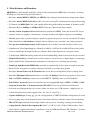
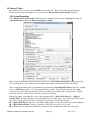
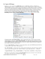
testing etc., proceed to install the device driver until 4 device drivers -- 2XInventa MPEG2 SAA7134
and 2XInventa MPEGIO2 VW2010 -- appear under the “ControlPanel->System->Hardware>DeviceManager->Sound, video and game controllers” category without “?” and “!” next to them:
Note 1. For multiple MPEGIO2 cards, each will have two pairs of “Inventa MPEGIO2 SAA7134”
and “Inventa MPEGIO2 VW2010” device drivers: one pair for each channel, two channels per card.
Note 2. If a channel lost a driver a warning dialog will appear and that channel will not be functional.
Note 3. Peripheral devices with the same hardware IDs as MPEGIO2, e.g. Inventa’s “MPEGIO” or
“MPEGIOPro” PCI cards, should not be used simultaneously with MPEGIO2 on the same PC.
Note 4. “All Programs->Inventa->MPEGIO2->SetupDrv.exe” can also install / reinstall drivers. (Note
on Windows 7 / 8, “SetupDrv.exe” needs to be run “as administrator” by right-mouse clicking the file
name then selecting “Run as administrator”).
Note 5: If PC boot up with MPEGIO2 card inserted but no device driver installed, each card will have
4 unknown devices under the “ControlPanel->System->Hardware->DeviceManager” window: these
must be upgraded to MPEGIO2 device drivers manually or by running the program “Start->All
Programs->Inventa->MPEGIO2->SetupDrv.exe”.
Note 6: Some PC motherboards might not shut down the PC properly after installing MPEGIO2 device
drivers: in this case putting the “ResetDrv.exe” from the MPEGIO2 Program Group into Windows’
“Startup” folder (“All Programs->Startup”) to reset the drivers usually can fix the shutdown problem.
MPEGIO2 Application Software Manual
Page 3
Ver. 1.0.2
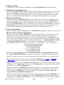
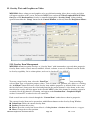
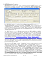
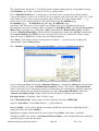
Application Software Installation
Once the Setup CD is inserted into PC’s CD drive, the Start.bat program will automatically start – if
this does not start double-click the “Start.bat” on the CD to start the setup process.
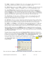
If Microsoft VC++2008 Redistributable or .Net Framework 3.5 is not detected their setup will begin
--- this will take a while --- then the MPEGIO2.exe “Setup Wizard” window will appear:
From this window, proceed to install MPEGIO2.exe application software.
At the end of the installation clicking the “Close” button will put
icon on Windows’ desktop.
Mouse double-clicking this icon will launch MPEGIO2.exe application program: it can also be
launched from Windows’ “Start->All Programs->Inventa->MPEGIO2” menu. Note if no
MPEGIO2 device driver exist this program simply displays a warning window and exit.
MPEGIO2 Application Software Manual
Page 4
Ver. 1.0.2
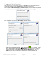
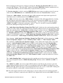
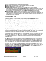
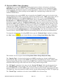
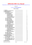
6. Device Architecture
Each MPEGIO2 channel has several major functioning units as illustrated below:
Following this illustration, the application software groups end-user controls to the hardware as
Video/Audio I/O, Graphics/Text Overlay, On-Screen Preview, MPEG encode/decode/stream and
Digital I/O. The 3 major processing IC chips are OSD IC, Preview IC and Codec IC: they are
responsible for overlay, preview and encoding/decoding respectively. Every MPEGIO2 card has 2
independent channels each with the same functions as listed above: the only inter-relationship between
them is under software control, they can route their video or audio output towards the matching
channel’s input (“matching channel” is the other channel on the same MPEGIO2 card).
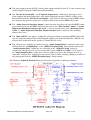
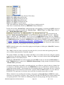
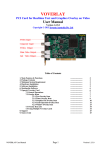
7. User Interface
On start up, the MPEGIO2 software presents a Video Window and a Control Window on PC screen:
Right-mouse single clicking the Video or Control Window will also display a Drop-down Menu:
MPEGIO2 Application Software Manual
Page 5
Ver. 1.0.2
7.1 Control Window
The Control Window has function buttons Setup, Record, Play, Stream, Overlay and Exit, it also
has a check box to turn on/off Video Preview (show/hide the Video Window).
The Control Window cannot be resized but will become hidden on the Windows’ Taskbar together
with the Video Window when “Minimize” item is selected from the Drop-down Menu.
7.2 Video Window
When turned on, Video Window is always located above the Control Window: it can be resized by
left-mouse clicking its edges then dragging. Left-mouse double-clicking will enter Full-Screen
mode: video content will occupy the entire desktop area in front of all other windows (doubleclicking again, or pressing the Space bar will revert back to normal window mode).
Left-mouse single-clicking inside Video or Control Window then dragging will move the Video
Window and Control Window together around the desktop.
When multiple MPEGIO2 channels are displayed, holding down the Ctrl-key then double-clicking
the left-mouse button inside any channel’s video area will expand that channel’s video to fully
occupy the entire video window (thus hiding all other channels’ video) --- double-clicking again
with Ctrl-key held-down will revert back to normal multi-channel display: see the Video Preview
& System Setup Section for more details on this feature.
The Video Window can also show MPEGIO2 channel’s recording or playing status when
recording or playing is started, as well as each channel’s number and TV signal type.
7.3 Drop-down Menu
Drop-down Menu appears when Right-Mouse Button is single-clicked inside the Video or Control
Window, or on the Taskbar Icon. Apart from various menu item selections, the Drop-down Menu
also reflects one channel’s status: if recording or playing is on or paused, streaming is on or off,
status is on, Overlay is off, etc.
MPEGIO2 Application Software Manual
Page 6
Ver. 1.0.2
7.4 Taskbar Icon
When the MPEGIO2.exe program is running, an icon will always appear at Windows’ Taskbar area:
, right mouse clicking this Icon will pop up the Drop-down Menu(Note if any
of the Setup Windows is open right-clicking will not pop up the menu). If any channel is recording,
streaming etc., they will also be indicated at this icon’s “tool tip” text when mouse cursor hovers
over this icon:
.
7.5 Total Channel Number
The Control Window also displays the number of MPEGIO2 channels currently found in the PC,
such as
. The MPEGIO2.exe program assumes this number will not change when it is
running. This number counts only those channels currently with their device drivers properly
installed. If a channel does not have its driver installed, or its driver is disabled, that channel will not
be counted. The sequential number of a channel (the “Current Chan” value used in the various Setup
Dialog Windows to identify each channel) might change as total number of channels change: if a
card or a channel is removed or added, the channel number of each channel previously existed could
also change.
7.6 Multiple MPEGIO2 Cards
Simultaneously running multiple MPEGIO2 cards in the same PC requires no special setup: the
MPEGIO2 device driver and application software will automatically recognize and count the total
channel numbers according to their properly installed device drivers. If a channel does not have its
device drivers installed due to failing hardware or deliberately disabled driver from the Windows’
Control Panel, that channel will not be counted in the total channel number and video/audio I/O on
that channel will not be functional, but functions of that channel’s matching channel on the same
PCIe card will not be affected except those functions related to its matching channel (routing A/V
to/from its matching channel). MPEGIO2 software allows max. 16 channels to be functional in one
PC: these channels can be from 8 or more PCIe cards
MPEGIO2 Application Software Manual
Page 7
Ver. 1.0.2
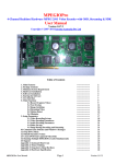
8. Breakout Box Sockets
All signal Input/Output are accessed through the sockets on the 2-Layer Breakout Box: its Top Layer
contains all Video/Audio Input sockets and the Digital I/O sockets; its Bottom Layer contains all
Video/Audio Output sockets. Since each MPEGIO2 card has 2 independent channels, the sockets on
the Breakout Box are arranged as Left Channel Sockets and Right Channel Sockets:
MPEGIO2 Application Software Manual
Page 8
Ver. 1.0.2
9. Video Input/Output
Each MPEGIO2 channel has 5 RCA(Composite) video input sources VIN0, VIN1, VIN2, VIN3, VIN4,
and one S-Video input source VIN5: VIN4 and VIN5 belong to the same “5Th Input” (they share the
same “brightness” signal line), while each of the VIN0~VIN3 can connect to a different external signal.
The Breakout Box only has VIN0, VIN3, VIN4 and VIN5 Input Sockets, since VIN1 is permanently
connected to the MPEG decoding (Playback) output, and VIN2 is left unconnected (always “no signal”).
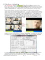
A channel uses 4 “Sub Windows” (0 ~ 3) to show input video and decoded MPEG video inside its
720X576/480-Pixel Video Frame: any of these 4 Sub Windows can use any of the 6 video input
sources (VIN0~VIN5) as its signal source, as shown below:
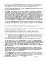
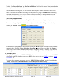
The “Video I/O Setup” Dialog is used to set up video input/output parameters:
This dialog can be opened from Control Window->Setup, or from Drop-down Menu->Setup.
MPEGIO2 Application Software Manual
Page 9
Ver. 1.0.2
The “Current Chan” combo box at the upper-left corner indicates which MPEGIO2 channel has the
Video I/O settings on the dialog, selecting a different channel number will immediately reflect the new
channel’s various settings in the entire dialog window.
The “Preview TV Signal” field below the “Current Chan” indicates the TV Signal type this channel
currently uses to display video preview and to encode MPEG video: this is always either PAL or NTSC,
it will NOT be no signal since the MPEGIO2 hardware always uses either NTSC or PAL to encode and
preview video. To manually force the channel to use either PAL or NTSC as its Preview TV Signal, use
the “TV Signal on This Input Src” combo box:
The “Video Input Source” combo box indicates one of the 6 “Video Input Sources” an MPEGIO2
channel has: VIN0~VIN3 RCA, VIN4 RCA and VIN5 S-Video. When this changes, the content in
“TV Signal on This Input Src” will reflect the Input Source’s current signal type, inc. “No Signal”
status. However, if manually force a PAL or NTSC signal type in the “TV Signal on This Input Src”
combo box, the “Preview TV Signal” field below the “Current Chan” combo box will also get that
signal type, indicating this channel’s video preview and MPEG encoding TV signal type has been
changed. By default, a channel set its video preview and MPEG encoding TV signal (the “Preview TV
Signal” field) according to its 1st video input source with signal currently being used by at least one of
its 4 “Sub Windows”: this can be manually overridden if a different PAL or NTSC signal type is
selected from the “TV Signal on This Input Src” combo box. Forcibly selecting a different PAL/NTSC
signal type this way therefore can be used to preview video and encode MPEG video in the PAL/NTSC
type different from a Video Input Source’s actual signal type, with MPEGIO2 hardware doing the realtime PAL-to-NTSC or NTSC-to-PAL conversion. Please note: do not forcibly change to different
PAL/NTSC signal type when a channel is encoding or decoding!
When MPEGIO2.exe program starts up, if all input sources used by some Sub Windows for a channel
have no signal, then the Country/Regional/Language setting in MS Windows’ Control Panel will be
used to decide NTSC or PAL is used as the “Preview TV Signal”: USA/Japan etc. will use NTSC, UK,
Australia etc. will use PAL: however, the command line switch –g can override this, see the section
“Command Line Parameters” for more details.
Each MPEGIO2 channel has 4 “Video Sub Windows”: they are selected from the “Sub Win No:”
combo box as “SubWin0 ~ SubWin3”. Each Sub Window can select a “Video Input Source” as its
input signal source: video from that input source will appear inside this Sub Window within the video
frame, or no video will appear if that input source has no signal. Clicking the “Connect Src to Sub”
button (between the “Video Input Source” and the “Sub Win No”) assigns the “Video Input Source”
to the “Sub Window”. Note same “Video Input Source” can be connected to multiple Sub Windows.
The VIN 0, VIN 3, VIN 4 RCA and the VIN 4 SVideo Input Sources are direct sockets on the top layer
of the Breakout Box: connecting external video sources to them will make the external signal type to
appear in the “TV Signal on This Input Src” combo box.
The VIN1 Input Source is always connected to the MPEG Decoding (Playback) output, the VIN2 Input
Source always has no signal since it’s not connected.
The “Set Positions” button arranges the positions of the 4 Sub Windows inside the video frame on PC
screen and on encoded MPEG video. The “Common Pos.” combo box provides common positions for
the 4 Sub Windows: 4-SubWindows Equal Split, SubWin 0 Full Screen, Picture-in-Picture, etc. Note
the “Sub Win Common Pos” selection from the Dropdown Menu has the same function.
The “Set Cropping” button will crop the size of the currently selected Video Input Source: it is
recommended to use the default values for the cropping for PAL and NTSC signals.
Below the “Sub Win No”, the “Sub Window Operation” groups operations on a Video Sub Window:
MPEGIO2 Application Software Manual
Page 10
Ver. 1.0.2
Enable: If cleared, this Sub Window will disappear from the video frame. By default sub window is enabled.
Freeze: If selected, the video inside the Sub Window will be frozen.
Border: Selecting this will place a white border around the Sub Window.
Border Blink: This will make the Sub Window’s border blinking.
Zoom: This will zoom the video inside the Sub Window when left mouse clicks inside the Sub Window with Shift-key
held down: the video from the point the Left Mouse clicked will be zoomed 2 times larger and this zoomed video
is shown inside the Sub Window. Left click again without holding the Shift-key will cancel the zooming.
Popup: This decides the display priority between Sub Windows when they overlay: when two Sub Windows overlap the
Sub Window with “Popup” selected will display on top of the Sub Window with “Popup” cleared. If both Sub
Windows have the same “Popup” selection (both selected or both cleared) then the lower numbered Sub
Window will have higher display priority.
H.Mirror: Selecting this will flip the video inside the Sub Window horizontally (swap left and right).
V.Mirror: Selecting this will flip the video inside the Sub Window vertically (upside down).
In the “Sub Window Colours” group, changing brightness, contrast etc. will affect colours for those
Sub Windows using the current “Video Input Source”. Clicking the “Set Default Colour” button will
restore the default colour settings.
Clicking the “Hori. Delay” will shift the horizontal start position of the entire video frame as follows:
Horizontal delay: must be within 0 ~ 63:
0 = - 32 Pixel delay
::
32= 0 Pixel delay (default)
::
63= + 31 Pixel delay.
Clicking the “Vert. Delay” will shift the vertical start position of the entire video frame as follows:
Vertical delay: can be within 0 ~ 31:
0 = -11 Lines delayed
::
12 = 0 Line delayed (default)
::
31 = +19 Lines delayed.
Note the “Hori. Delay” and “Vert. Delay” buttons only affect the VIN0 ~ VIN3 Input Sources.
The 5th Video Input Source has its own settings for video horizontal and vertical start/stop positions via
buttons “VIN4 Horizontal Start/Stop”, “VIN4 Vert. Blank Start/Stop” and “VIN 4 Auto Crop”. Its
video signal source can be either externally from the RCA(VIN4)/SVideo(VIN5) sockets on the
Breakout Box, or internally from the matching channel’s video output by ticking “VIN 4 Input from
Matching Chan” --- ticking/clearing this box will also power down/up the 5th Video Input IC (the
matching channel number is also displayed if the matching channel exists). Please do not tick the “VIN
4 Input from Matching Chan” on a channel and its matching channel simultaneously: the result will
be undefined.
Note when socket VIN5 (SVideo) has signal input but socket VIN4 (RCA) doesn’t and a Sub Window
selects VIN4 as its input source, or when socket VIN4 (RCA) has signal input but socket VIN5 (SVideo)
doesn’t and a Sub Window selects VIN5 as its input source, that Sub Window will show black & white
video because socket VIN4 and socket VIN5 share the same Brightness signal line.
Clicking the “VIN 4 IC Reset” button momentarily power-down the 5th Input IC then power it up again.
The “ROM *” field next to the “VIN 4 IC Reset” button is the 5th Input IC’s software (ROM) version:
this can be 0 as the original version, or 0x8C as the downloaded latest version if the box “PatchROM”
is ticked: note if the 5th Input signal shows incorrect colour changing the ROM version could rectify the
problem. To revert the ROM version to original 0 clear the “PatchROM” box then reboot the PC.
The “VIN4 Horizontal Start/Stop” has these limits for its start and stop values:
MPEGIO2 Application Software Manual
Page 11
Ver. 1.0.2
start: a signed integer value: -512 ~ +511: the number of pixels to blank out before/after the first horizontally active pixel,
default is 0.
stop: a signed integer value: -512 ~ +511: the number of pixels to blank out before/after the last horizontally active pixel,
default is 0.
The “VIN4 Vert. Blank Start/Stop” has these limits for its start and stop values:
start: a signed char value: -128 ~ +127: The Vertical Blank Area will appear (in number of lines of displayed video)
before (when value is negative) or after (when value is positive) the standard vertical blanking intervals
Default is 0: Same time as start of the standard vertical blanking interval.
stop: a signed char value: -128 ~ +127: The Vertical Blank Area will end (in number of lines of displayed video)
before (when value is negative) or after (when value is positive) the standard vertical blanking intervals,
Default is 0: Same time as stop of the standard vertical blanking interval.
If the “VIN 4 Auto Crop” check box is ticked, the combo box to its right will select the horizontal
active video size for the 5Th Video Input: 720 Pixels(default), 704 Pixels, or 640 Pixels.
The “VIN 4 Luma AGC” and “VIN 4 Chroma AGC” set up the Automatic Gain Control for the 5th
Input Source (VIN 4)’s Luminance and Chrominance, default are enabling AGC.
The “VIN 4 WP Disable” and “VIN 4 LP Disable” allow disabling the White Peak Detection and
Luminance Peak Detection processing for the 5th Input Source(VIN 4), their default are both “Enable”.
If the “Auto Switch PAL/NTSC” check box is ticked, this channel’s Preview and MPEG encoding TV
Signal type (the “Preview TV Signal”) will follow the current “Video Input Source” as its signal
changes to NTSC or PAL (note Auto Switch only happens when the channel is not encoding or
decoding).
The “7.5IRE Black Level” is only useful for Non-Japanese NTSC type video signals. Ticking this box
will make the video’s black area darker.
Ticking the “Input ColourBar” box displays a colour bar in a channel’s video preview area (but not in the Video
Loopback RCA/SVideo ports of the Breakout Box); this colour bar also appears in the encoded / streamed
MPEG video and its setting/clearing status will be remembered by the application software:
At the bottom area of the Video I/O Setup dialog:
“Background Colour” set up the colour for the area inside an MPEGIO2 channel’s Video Preview Window
where no Sub Window covers (thus exposes the “Background” of that channel). Default is Black.
“Blank Colour” is the colour appearing in Video Sub Windows that have no video signal from their Video Input
Source and the channel’s “Video Loss Indication” is “Filled with blank colour”. Default is Blue.
“Video Loss Indication” selects the action taken when a Sub Window has no signal in its Input Source:
No action(Default), Keep last image, Filled with blank colour, Keep last image & blink border.
When selected, the “Load Default Settings” combo box loads the default register values into one of the
3 I/O ICs for a channel: the OSD/Video Input IC for Preview/Encode, the 5th Video Input IC for the 5th
Input Source (VIN 4 RCA and VIN 4 SVideo), and the Video Output IC for MPEG decoding and
Loopback Output ports.
MPEGIO2 Application Software Manual
Page 12
Ver. 1.0.2
--- each of these default register value sets have different PAL and NTSC versions:
.
The “Load Regs:” button and the ComBo box to its right allow loading an arbitrary file containing an
IC’s register number+value pairs into the OSD, VIN4 or Output ICs, mainly for debugging purpose.
Adjusting the “VIN 0~3 White Peak Detect Threshold” value can affect the amount of white colour
being cut-off but can reduce chances of white background flickering: default value is 216, valid value
range is 0 ~ 254. Using value 255 will turn off automatics white peak control. Note this button only
affects the VIN 0 ~ VIN 3 input sources: the 5th Input Source has its own automatic white peak control.
The “Auto AGC” check box enables Automatic AGC Gain Value setting, clearing this box will enbale
the “AGC Gain” and EditBox next to it allowing manual setting of AGC Gain values (0 ~ 511 allowed):
this will affect the brightness of the VIN 0 ~ VIN 3 Video Input Source.
The “AGC Norm. Max Gain” and “AGC White Peak Gain” will also affect the VIN 0 ~ VIN 3 Video
Input Source brightness. A high “AGC Norm. Max Gain” value could also cause video shivering.
The “OSD-to-Preview Use YX/CX” boxes (only one can be ticked) are for debugging purpose : ticking
them will make the OSD IC to Preview IC connection to use CVBS signal instead of Y/C.
Each MPEGIO2 channel has 2 pairs of Output Video ports on the bottom layer of the Breakout-Box:
the Video Loopback RCA/SVideo Out ports show the video on PC screen and encoded/streamed as
MPEG video inc. all overlays items but excluding the “Input ColourBar” ticked below the “7.5IRE
Black Level” box; the MPEG Decode RCA/SVideo Out ports show video decoded from MPEG file as
full screen without any overlay or the “Input ColourBar” even if they are defined (overlay and the
“Input ColourBar” can still appear on PC screen).
The “Output1 ColourBar” display a colour bar at the MPEG Decode RCA/SVideo Out ports.
The “Output2 ColourBar” display a colour bar at the Video Loopback RCA/SVideo Out ports.
Note these 2 colour bars are for debugging only, they won’t be remembered by the application software.
The “Output1 BlankLevel” fields show and adjust the video blank level for the MPEG Decode
RCA/SVideo Out ports (J11, J6, J3, J8 on the Breakout Box).
The “Output2 BlankLevel” fields show and adjust the video blank level for the Video Loopback
RCA/SVideo Out ports (J9, J1, J5, J17 on the Breakout Box).
The “Reset Preview” button will re-initialize the Video/Audio Preview IC's Register Values to their
default ones as the device driver “Drv7134.sys” contains, as in the PCIe card’s power-on stage: this
button can only be used when Video Preview is not in progress.
The “Restart Preview” button quickly stops then restarts Video Preview on this MPEGIO2 channel.
The “Reset VIN0~3 IC” button hardware reset the Video Input/OSD IC for the VIN 0~3 input: this is
useful to fix garbled video display in any Sub Window, e.g. when doing PAL/NTSC switching, etc.
MPEGIO2 Application Software Manual
Page 13
Ver. 1.0.2
10. Audio Input/Output
The “Audio I/O Setup” dialog window can be opened from the “Setup” button on the Control Window,
or from the Drop-down menu->Setup.
Each MPEGIO2 channel has 3 Audio Input Sources selectable from the “Audio Chan” Combo Box:
the 1st input source is the Audio 1st Input Line-In socket on the Top Layer of the Breakout Box;
the 2nd input source is the Audio 2nd Input Line-In socket on the Top Layer of the Breakout Box;
the 3rd input source is the MPEG decoding audio output from this MPEGIO2 channel.
The 4th item (“MPEG Decoder Output”) in the “Audio Chan” Combo box is not an audio input source
for the MPEGIO2 channel, it is the audio signal to be heard on the “MPEG Decode Audio Out” Ports
on the Bottom Layer of the Breakout Box: it is listed here only for adjusting its left/right sub-channel
output gains.
Audio signals from the 3 input sources can be mixed to be simultaneously heard on PC’s speakers and
on the Audio Loopback Output port on the Breakout Box, as well as to be encoded/streamed-out with
MPEG video. Their left and right sub-channel gains can be adjusted individually.
To enable audio input/output and preview, the “Init Audio” button can be used to initialize a channel’s
audio. If the check box “No Init on Startup” is cleared (default), this MPEGIO2 channel will initialize
its audio ICs automatically when the software starts, therefore no need to click the “Init Audio” button.
Typing values between 0~79 in the “Left Gain” or “Right Gain” edit box will affect audio input gains
immediately on the left sub-channel or right sub-channel of the current “Audio Chan”: this will affect
PC speakers, audio encoded to MPEG stream, and Audio Loopback Output Ports on the Breakout Box.
Use the “Audio Preview On” check box to turn on / off the audio preview (hear audio on PC’s sound
card/speakers, unrelated to audio encoding to MPEG file/stream). When audio preview is on, use the
“Preview Volume” slider to adjust audio volume heard from PC speakers: this volume will not affect
MPEG encoding nor audio heard from the Audio Loopback Output sockets on the Breakout Box.
MPEGIO2 Application Software Manual
Page 14
Ver. 1.0.2
Prior to turning on audio preview, ticking or clearing the “Preview Use WaveOut API” box selects
using the MS Windows’ “WaveOut API” (default, for multiple MPEGIO2 channels simultaneous use)
or “DirectSound API”(use for one channel only) to play the audio as preview.
If “Preview Auto On” is ticked, each time MPEGIO2.exe starts it turns on audio preview if it was on
when last time MPEGIO2.exe exit ("Audio Preview On" ticked and “Pause Preview” cleared).
Ticking the “-6dB on Input” check box will apply -6dB reduction on the input audio signal for all
audio input sources simultaneously for this MPEGIO2 channel.
The “Mute” check box (next to the “-6dB on Input”) will mute all the audio input channels: selecting
this will make no audio heard on PC speakers, on the encoded/streamed-out MPEG data, and on the
audio Loopback Output ports J20/J25 on the Breakout Box --- the only exception is when the button
“OSD IC as AADC” is ticked the audio from “Audio 2nd Line-In” can still be encoded into MPEG
file/stream (although not being heard on PC speakers).
The “Audio Input from Matching Channel # on This Card” (# indicates the actual matching channel
number if it exists) allows the audio output from the matching channel to be used as this channel’s audio
input (thus ignoring all the “Audio Chan” and Gain settings): to achieve this, the “Matching Channel”
must check its “Audio Output to Matching Channel on This Card”: e.g., if channel 0 and channel 1
are “Matching Channels” on the same MPEGIO2 card, and channel 1 wants to use channel 0’s audio
output as its audio input, channel 1’s “Audio Input from Matching Channel on This Card” should be
ticked, and channel 0’s “Audio Output to Matching Channel on This Card” should also be ticked.
Note changing “Audio Input from Matching Channel # on This Card” will also change the “Audio
Source for Speakers Output” to either “Matching Chan’s Audio” or “This Channel’s Audio”.
The combo box “Audio Source for Speakers Output” selects which audio output will be sent to this
channel’s “Audio Loopback Output” sockets (J20/J25) on the bottom layer of the Breakout Box:
either this channel’s audio output, or the matching channel’s audio output. Selecting “No Output to
Speakers” disables audio output on the “Audio Loopback Output” sockets. Note if “OSD IC as
AADC” is ticked, “Audio Source for Speakers Output” will also affect encoded MPEG audio(see
below): if Audio Input is from matching channel(the “Audio Input from Matching Channel # on This
Card” is ticked), then the “Audio Source for Speakers Output” must select “Matching Chan’s
Audio” to make the audio to be encoded into MPEG data; if Audio Input is not from the matching
channel(the “Audio Input from Matching Channel # on This Card” is cleared), then the “Audio
Source for Speakers Output” must select “This Channel’s Audio” to make the audio to be encoded
into MPEG data.
The “Audio Sampling Rate” combo box shows the sampling rate used to preview and encode audio:
this is only changeable from the “MPEG Encoding Setup” Window, unless “OSD IC as AADC” is
selected:
The “OSD IC as AADC” box selects if the OSD IC (ticked) or the Preview IC (cleared) is to be the
Audio Analog-to-Digital Converter (ADC) to send digitized audio to the MPEG encoding IC to create
MPEG audio. By default, this box is cleared meaning the Preview IC is used as audio ADC. Ticking this
box will use OSD IC as audio ADC, which will bring over some changes:
The audio output of the Preview IC (which always does the audio preview for audio heard on PC
speakers) will now be connected to the OSD IC to be digitized then sent out to the MPEG Codec IC;
MPEGIO2 Application Software Manual
Page 15
Ver. 1.0.2
The audio output from the OSD IC (not the audio output from the Preview IC) is now sent out to the
Audio Loopback Out ports J20/J25 on the Breakout Box;
The “Encode & Out Amplify” and “Loopback Output Gain” combo boxes will appear: these
allow changing the audio output gains at the Audio Loopback Out ports (J20/J25 sockets) on the
Breakout Box, and the “Encode & Out Amplify” value will also affect the encoded MPEG audio:
note using too big gain here could cause corrupted audio in the encoded MPEG file/stream;
The “Audio Source for Speakers Output” combo box now also affects the encoded MPEG audio:
to get audio encoded in the MPEG file/stream this must select “This Channel’s Audio” if “Audio
Input from Matching Channel on this Card” is cleared, and this must select “Matching Chan’s
Audio” if “Audio Input from Matching Channel on this Card” is ticked (and the matching
channel does exist);
The “Mute OSD IC” box appears: ticking this will stop encoding all audio into MPEG file/stream
and also stop audio output at the Audio Loopback Output ports on the Breakout Box (J20/J25), but
will not affect audio heard on PC speakers (if Audio Preview is on);
The audio preview sampling rate indicated by the “Audio Sampling Rate” combo box now can be
different from the “Sampling Rate” in the “MPEG Encoding Setup” dialog window, this makes
“Audio Sampling Rate” combo box user-selectable in the “Audio I/O Setup” dialog. In
comparison, when preview IC is used as audio ADC (when “OSD IC as AADC” box is cleared),
the “Audio Sampling Rate” combo box is always disabled, because when using preview IC as
audio ADC audio preview sampling rate must be the same as audio encoding sampling rate which is
only changeable from the “MPEG Encoding Setup” dialog window.
The following Audio I/O Diagram illustrates how audio signal flows in different situations:
MPEGIO2 Application Software Manual
Page 16
Ver. 1.0.2
11. Video Preview & System Setup
The “Preview Video” check box
on the Control Window turns on/off the Video
Preview for all channels. When turned on, video from MPEGIO2 channels will appear inside a floating
window that user can move, resize, minimize or maximize. Holding-down the left mouse button in the
Video or Control Window then dragging will move the two windows together around the desktop.
Double-clicking left mouse button inside the Video Window will expand it to full-screen mode:
double-clicking again will restore back to normal display. If the Ctrl-key is held-down while left mouse
double-clicking inside the Video Window, no full-screen will happen, but the channels inside the Video
Window will toggle between “one channel” mode and “all channels” mode: in “one channel” mode,
the channel area the left-mouse double-clicked will expand to fill the entire Video Window; while in
“all channels” mode, all channels will display their video inside the Video Window with equal width
and height (Note selecting the “Single/All Chan Preview” Item in the Drop-down Menu also switch
between “one channel” mode and “all channels” mode):
Parameters to control the Video Preview are inside the “System Setup” dialog that can be opened from
the “Setup” button on the Control Window, or from the “Setup” menu from the Drop-down Menu:
In the “System Setup” dialog window, the “Channels per Row” controls how many channels will be
arranged per row in the Video Preview Window: 0 is the same as the total number of channels.
Depending on the value entered, the number of rows will be automatically calculated, e.g., putting
MPEGIO2 Application Software Manual
Page 17
Ver. 1.0.2
number 2 for a PC with 4 MPEGIO2 channels installed (2 cards) will display 2 rows of channels each
with 2 channels. By default, all channels will be displayed in a single row. After changing this value,
turn-off then turn-on Video Preview from Control Window to see the new arrangement.
Selecting the “Start with Video Preview” will make the MPEGIO2.exe program to automatically start
the Video Preview when the program starts.
The “Monitor” combo box only appears when the PC has multiple monitors attached, it indicates the
physical Monitor (screen) Number to display live video preview: this field is only modifiable when
Video Preview is turned off. Changing this value then turning on the Video Preview will make live
Video to appear when the Video Preview Window is in the designated monitor. Note live video will not
appear (the preview window has no video) when Video Preview Window is moved to a monitor other
than the one indicated by this Monitor Number. When PC has multiple monitors number 0 might not
necessarily be the primary monitor: if the selected Monitor does not show live video, some other
monitor will do. MPEGIO2.exe remembers the currently used Monitor Number on exit and will use it
on its next start-up. By default, the MPEGIO2.exe uses the primary monitor number for video preview.
The “Preview, Image and Encoding Colour” scrollbars adjust colour properties for video inside the
Video Preview window, for captured still images, and for the encoded MPEG video. The “Set Default
Values” button will restore these colour parameters to their default values.
The “Preview Colour” (Bright/Contrast/Saturate) indicates and adjusts the colour on previewed
video only, without affecting colours on captured still image and MPEG recording video.
The button “Video Preview Src Clip” set the Video Preview Source Clipping Pixels for an MPEGIO2
Channel: the values in the X, Y, R, B edit boxes indicate:
X: the pixels to include (when negative) or exclude (when positive) from the left edge of the incoming video
Y : the pixels to include (when negative) or exclude (when positive) from the top edge of the incoming video
R: the pixels to include (when positive) or exclude (when negative) from the right edge of the incoming video
B: the pixels to include (when positive) or exclude (when negative) from the bottom edge of the incoming video
Note 1: To preview a smaller portion of the incoming video's raw frame(e.g. to avoid noise at edges),
set X and Y to positive, R and B to negative: this will use a smaller portion of the raw video
input to fill the video preview window, the visual result is the video is “zoomed in” (enlarged).
Note 2: The default settings are: X = Y = R = 0, B = -12.
Note 3: This clipping will not affect still image captured, nor encoded MPEG video on this channel.
The “TV Signal” field to the right of the “Current Chan” is the same as the “Preview TV Signal”
field in the “Video I/O Setup” dialog window: it shows the video signal type this MPEGIO2 channel is
currently configured to use and will affect the video preview and MPEG encoding. This setting defaults
to the signal type the first Input Source with signal this channel’s Sub Windows use, but can be
manually changed by selecting the “TV Signal on This Input Src” combo box inside the “Video I/O
Setup” dialog window.
The “Reset Input” button will hardware reset the OSD and Video Input IC on the PCIe card for this
channel: use this with caution! Because this will clear all video display and Overlays on this channel --after doing this, only selecting the “Load Default Settings” combo box on the “OSD IC PAL” or
“OSD IC NTSC” item can restore the video display.
The “Load Default Settings” combo box allows loading default register values to one of the 3 major
ICs on the MPEGIO2 card for a channel: the OSD and Video Input IC, the 5th Video Input (VIN4) IC,
and the Video Output ICs, each of them has PAL and NTSC versions. This is the same as the “Load
Default Settings” combo box inside the “Video I/O Setup” dialog window.
MPEGIO2 Application Software Manual
Page 18
Ver. 1.0.2
The “Reset Preview” is the same as in the “Video I/O Setup” dialog: re-initialize the Video/Audio
Preview IC's Register Values to their default ones as the device driver “Drv7134.sys” contains, as in the
PCIe card’s power-on stage: this button can only be used when Video Preview is not in progress.
Clicking this button will also set the “Preview Register Delay” value which might affect audio preview
result, so normally should leave the default value unchanged.
The “Confirm on Exit” turns on or off the “Are You Sure to End MPEGIO2 Application” dialog
box display when exiting the MPEGIO2.exe program.
The “ColourBar” box is the same as the “Input ColourBar” box in the “Video I/O Setup” dialog.
Ticking the “No ToolTip” will stop all ToolTip display throughout the MPEGIO2.exe application.
The “Preview Text Font & Positions” group controls the 2 line Status Text on the surface of the
previewed video (they will not appear in encoded MPEG video, nor in the output of the Video
Loopback Output ports on the Breakout Box):
The “Show Status” will turn on or off the status lines;
The “Text Font” will display font selection dialog for choosing font for the preview text;
The “Text1 X/Y” are the 1st preview text line’s left and top positions inside the video frame;
The “Text2 X/Y” are the 2nd preview text line’s left and top positions inside the video frame;
The “Set Position” button can instantly update the X/Y positions for the 2 line status text.
The 1st preview text line contains channel number and its TV signal type, such as 0:PAL, 2:NTSC, etc.
The 2nd preview text line contains the channel’s recording/decoding status, such as “Rec: 0:01:28.
102MB MPEG1.mpg”, meaning the channel has been recording for 1 min 28 sec. with 102Mbytes data
recorded in file “MPEG1.mpg” under the current recording folder.
The “Text2 Y Shift” field shifts the 2nd preview text line vertically up or down, since the “Text2 Y”
field is automatically calculated by the program and cannot be changed manually.
The “Preview Deinterlace” field is for Windows 7 or above only: selecting deinterlacing method on
video preview --- deinterlacing can reduce fuzziness on fast moving objects’ edges:
The “Odd to Even” method means copying Odd lines to Even lines within each video frame.
The “Even to Odd” method means copying Even lines to Odd lines within each video frame.
The “20% Screen” ~ “90%Screen” methods indicate conditional indeterlacing: Using “Odd to Even”
deinterlace only when Video Preview area exceed 20% ~ 90% of the desktop window’s width or height.
The read-only “Left Chan” (Or “RightChan”) field below the “Current Chan” combo box indicates if
the current channel is the Left Channel (the 1st) or the Right Channel (2nd) on the MPEGIO2 card.
The read-only “Bus # Dev No. #” field indicates the PCI ICs’ Bus and Device (Preview and MPEG
Codec ICs) Numbers for this MPEGIO2 channel.
The “PCB Ver.” Field indicates the detected PCB board version of the MPEGIO2 channel: a value 3 or
higher is correct; a value 2 indicates switch IC failure, a value 1 indicates Input 5 IC failure.
MPEGIO2 Application Software Manual
Page 19
Ver. 1.0.2
12. Overlay Text and Graphics on Video
MPEGIO2 allows colour text and graphics to be overlaid on incoming video: these overlay and video
will appear together on PC screen, on encoded MPEG data, and on the Video Loopback RCA/S-Video
Out ports of the Breakout Box. Overlay is controlled through the “Overlay Setup” dialog window,
opened from either the “Setup” button on the Control Window, or directly from the Drop-down Menu:
12.1 Overlay Item Management
MPEGIO2 channels organize overlays as “Overlay Items” with item number, type and other properties.
Overlay Items can be created, moved, modified, deleted, redrawn, or erased. A channel can also disable
its Overlay capability, list its colour palette, and reset its Overlay IC (i.e. OSD IC).
To create a new Overlay item, select the “Item Type”:
, then according to
selected Item Type, assign other property values., such as colour, text, position, size, alpha, etc. Clicking
the “Add Item” button will create a new Overlay item with the properties as defined on the screen, and
the Overlay Item is drawn over the video background in the current channel’s video frame: at the same
time this new overlay will also appear in the encoded MPEG video if the channel is encoding, appear in
streamed video if the channel is streaming, and appear on the Breakout Box’s Loopback Output
sockets if external TV or other devices are connected.
Each created item can be selected through the “Current Item” combo box to show its properties.
The current Overlay Item can be operated on with different buttons on the Overlay Setup Window:
Delete Item: Delete the current Overlay Item.
Redraw: Redraw this overlay.
Erase: Erase the overlay but do not delete it: clicking Redraw or Redraw All will make it to reappear.
Move: Change the overlay position.
MPEGIO2 Application Software Manual
Page 20
Ver. 1.0.2
There are also buttons that operate on all existing Overlay Items:
Clear Screen: Erase all overlays on the video frame but do not delete them.
Redraw All: Redraw all existing overlay items.
Disable Overlay: Tick to hide all overlays, clear to make them to reappear instantly.
When this button is ticked it disables the MPEGIO2 channel’s capability to display any overlay: all
overlay items will disappear but remain undeleted. This option can be used as a quick way to turn
on/off the defined overlay items instantly. Note the Drop-down menu also has this option.
Reset Overlay IC: Hardware reset the OSD (Overlay) IC and redraw all overlays, this will
reload the OSD IC’s default register values: current overlay items will be redrawn, but all Video I/O
setup will revert to their default settings, e.g., the Video Sub Windows’ placement will return to the
default 4-SubWindow Equal Split.
12.2 Overlay Item Types
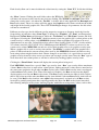
Each Overlay Item has an Item Type, the currently supported Overlay Item Types include:
Text: ASCII/Unicode text with foreground/background colour, font, alpha, blink: many items allowed.
Timer: Time, Date with Time or Counter can be created with colour, font, alpha, only one item allowed.
Rectangle: Colour rectangles with width and height and alpha transparency, many items allowed.
Graphics: Graphics files(.bmp, jpg, gif, etc.) of 8-bit/256 colour and transparency, many items allowed.
Box: Colour box with width and height and alpha values different from non-box items, 4 items allowed.
Note the “Font” button for Text/Timer overlay items offers limited selection of colours: to set more
colours to Text/Timer overlays use the “FrGr Colour” (Foreground Colour) button.
The “Unicode” check box only appears when Item Type is Text: to input Unicode (double-byte) string
as Text Overlay, tick this box and select some Unicode font from the “Font” button, also use appropriate
keyboard input method from Windows ControlPanel, e.g. Chinese, Japanese or Korean.
Overlay items can have Alpha for transparency: all the Text, Timer, Rectangle and Graphics type items
share the same Alpha values: 25%, 50% or 75% transparency against their background video. An item
can also have no transparency (no Alpha) which means it is solid colour fully visible in front of its
background video.
The “Box” type overlay items have their own colour and Alpha transparency values defined separately
from the non-Box items. They also have higher display priority over non-Box items as explained later.
When more than one Overlay Items have been created for a channel, use the “Current Item” combo
box to select among them: each Overlay Item’s properties will appear immediately in property fields.
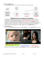
All Overlay Item Types except the Graphics Item have Colour Property: Foreground Colour is used to
draw the overlay items, Background Colour for the Text and Timer Overlay Items is used to show the
background in between character strokes. The Background Mode for Text and Timer Items can be
either Transparent or Opaque, as illustrated here:
.
MPEGIO2 Application Software Manual
Page 21
Ver. 1.0.2
Each Overlay Item can be moved within the video frame by setting the “Start X,Y” fields then clicking
the “Move” button. Clicking the small sliders above the X/Y fields
will move the current overlay item by one pixel per clicking. The W(idth) and H(eight) values will
change the overlay item’s size when the “Set Size” is clicked: this is only applicable for Rectangle and
Box overlay items. These size values will also appear for Graphics overlay items to indicate the width
and height of the loaded graphics file. These X/Y/Width/Height changes are permanent: the old values
will not be remembered.
Different overlay types decide different overlay properties to appear or disappear inside the Overlay
Setup dialog: in particular, when “Item Type” is changed to “Graphics”, the “Font” and Foreground,
Background Colour Boxes will disappear, while the “Use Palette” and “File Name” buttons and field
will appear. Selecting the “Use Palette” check box means to use the graphics file’s colour palette as the
current overlay’s colour palette: each MPEGIO2 channel allows maximum 252 colours to be used
simultaneously at any time, Colour Palette(also called Colour LookUp Table “CLUT”) decides which
252 colours out of the 256 X 256 X 256 = 16Million possible RGB/YUV colours can be used as the
current active colour. MPEGIO2 can only use 8-bit colour graphics files as its graphics overlay item.
When a graphics file is used as overlay item and the “Use Palette” is ticked, and if the graphics file’s
palette is different from the current colour palette used by this MPEGIO2 channel, the other overlay
items using colours might also have their colours changed: to avoid this, it is a good idea to create all
graphics overlay items first, then create text, timer and rectangle overlay items. Note the “Box” type of
items have their own colour palette so will not be affected by loading graphics overlay items.
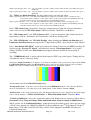
Clicking the “Show Palette” button will display the current palette being used.
Each MPEGIO2 channel has a special “Box” type overlay item: “Box” type overlay allows maximum
4 items. Box overlays has its own colour, colour palette, alpha transparency values that are unrelated to
the same-name properties for all other non-Box overlay items. When a Box overlay item is overlapped
with non-Box overlay items (Text, Timer, Rectangle or Graphics), the Box overlay item has higher
display priority over the non-Box overlay items: if the Box overlay item has no alpha (is fully visible)
then it will sit on top of the other non-Box overlay items behind it (the non-Box overlay items will not
be seen). If the Box overlay item has some alpha value transparency assigned to it, the Box overlay
item will be partially transparent thus exposing partially the other non-Box overlay items beneath it,
thus allowing multiple overlay items showing together with different transparency values, such as this:
MPEGIO2 Application Software Manual
Page 22
Ver. 1.0.2
Each channel can have at most one Timer overlay: Timer overlay can choose “Format” values:
Timer Only, such as:
Date+Time, such as:
Counter, either numerical form like
, updated every 300 ms;
, updated every 300 ms;
, or H:M:S form like
.
When Timer overlay is using “Counter” format, several extra properties will appear:
The “Start” and “Stop” values are displayed when the counter starts and stops counting. The “Step”
value is in 100ms unit: it is the time interval to increase/decrease the counting value by 1, e.g.:
Start:1, Stop:100,Step:2 will start counting from 1 towards 100 with value increasing 1 per 0.2 second;
Start:0, Stop:60,Step:10 will start counting from 0 towards 60 with value increasing 1 per 1 second;
Start:100, Stop:1,Step:-5 will start counting from 100 towards 1 with value decreasing 1 per 0.5 second.
The “Erase on Stop” option decides if the counter’s last value will be erased when the counter reaches
its Stop value: ticking this check box will erase the last value, clearing it will keep the last value on the
video frame after the counter stops.
When all parameters are set up properly for a Counter Overlay, click the “Start Counter” button
to start counting -- once started, this button becomes “Stop Counter”
so
clicking it again will stop counting. Counter overlay can also be started / stopped by Digital I/O Pin
status change.
The “UpdateText” button appears only when current item type is Text: this button uses new text typed
in the “Text:” EditBox and “Start X/Y” positions to update an existing text overlay item: in comparison,
the “Redraw” button (next to the “Current Item”) redraws the item with the existing contents.
The check boxes “IncreaseY” and “WrapY” also only appear when current item type is Text: ticking
the “IncreaseY” means each time button “UpdateText” is clicked, the vertical (Y) position of the
current text overlay item will be automatically increased by the height of the text string before
redrawing. Ticking the “WrapY” means when automatically increased Y position reaches the bottom of
the video frame, the next new Y position for automatically updated text redrawing will wrap back to the
original Y value used when the Text item was initially created. If “WrapY” is not ticked, then when Y
position reaches the bottom of the video frame, the automatically updated text will stay at the last line of
the video frame, shifting all previously automatically updated text lines upwards by one line.
Note the Y position automatically updated in this way is temporary: once the MPEGIO2.exe program
exit and restarts, the original Y position used when the Text item was created will be restored. In
comparison, the Y(and X) values changed through the “Start X/Y” EditBoxes are permanent: they will
be used when MPEGIO2.exe program exit and restarts.
MPEGIO2 Application Software Manual
Page 23
Ver. 1.0.2
13. MPEG Encoding Parameters
MPEGIO2 channels can encode their Video / Audio Preview contents into MPEG data to be saved as
file or streamed over network, encoding parameters are set up from the “MPEG Encoding Setup”
dialog opened from the Setup button on the Control window, or from the Drop-down Menu->Setup:
Each MPEGIO2 channel can be configured either as Program Stream MPEG encoder or as
Transport Stream MPEG encoder: selected from the “Encoder Type” combo box to the right of the
“Current Chan”. This “Encoder Type” decides the encoded MPEG data format as either Program
Stream or Transport Stream, it also decides the MPEG data the channel can decode: Program Stream
channel can only decode Program Stream MPEG data, Transport Stream channel can only decode
Transport Stream MPEG data.
The “MPEG Type” box next to the “Encoder Type” designates the MPEG1, MPEG2, or MPEG4
format of the encoded video/audio, while the “Mux Type” further next decides if the input video and
audio are multiplexed into the encoded MPEG stream as Video & Audio, or encoded as Video Only
without Audio. Note while MPEG2/MPEG1 video can be played back by almost all software video
players, MPEG4 video playback is less universal: known software players that can play MPEGIO2
encoded MPEG4 video include VideoLan(vlc.exe), SMPlayer, KMPlayer, ffplay.exe (ffmpeg),
MainConcept ShowCase, DiVX Plus Player, Total Video Player, Elecard MPEG Player, GOM Player,
etc. MPEG4 encodes higher quality at low bit rates when compared with MPEG2 encoding at the same
low bit rates. MPEG2 video can create DVD/SVCD movie disks, MPEG1 video can create VCD movie
disks. Note setting MPEG1 format must make sure Horizontal Size <= 352, Vertical Size <= 288/240
pixels or encoding failure will appear.
The read-only field “TV Signal” below the “Current Chan” indicates the signal format of the encoded
MPEG video: either PAL or NTSC – this is consistent with the “Preview TV Signal” field in the
“Video I/O Setup” dialog and the “TV Signal” field in the “System Setup” dialog. Note this can only
be changed manually from within the “Video I/O Setup” dialog by forcibly setting the “TV Signal on
This Input Src” combo box to PAL or NTSC. By default, an MPEGIO2 channel automatically set its
video preview and MPEG encoding TV signal (thus the “Preview TV Signal” field in Video I/O Setup
dialog, the “TV Signal” fields in “System Setup” and “MPEG Encoding Setup” dialog windows)
according to its 1st video input source with signal currently used by at least one of its 4 “Sub Windows”:
this can be manually overridden if you deliberately select a different PAL or NTSC signal type from the
“TV Signal on This Input Src” combo box in the “Video I/O Setup” dialog window --- this might be
necessary if none of the 5 Video Input Sources has incoming signal and you still wish to encode MPEG
video (e.g. create timer / counter Overlay on some static background bitmaps).
MPEGIO2 Application Software Manual
Page 24
Ver. 1.0.2
The various options under the “Video Encoding Parameters” group:
Hori. Size: the encoded video frame’s horizontal width in pixels: 176 ~ 720
Vert. Size: the encoded video frame’s vertical height in pixels: 144 ~ 576 for PAL, 144~512 for NTSC
(MPEG1 format must make sure Horizontal Size <= 352, Vertical Size <= 288/240 pixels)
Maximum Bit Rate: Encoded Maximum Video Bit Rate in K bit per sec., within 128Kbps ~ 15Mbps
Average Bit Rate: Encoded Average Video Bit Rate in K bit per sec., within 128Kbps ~ 15Mbps
Note 1: Maximum/Average Bit Rates are only applicable to VBR(Variable Bit Rate);
for CBR(Constant Bit Rate), only Maximum Bit Rate exists, or Max=Ave Bit Rates.
Note 2: Average Bit Rate must be <= Maximum Bit Rate
Note 3: Depending on the Encoding Hori./Vert. Size(Frame Size), the hardware has the following
Minimum Encoding Bit Rates:
132Kbps for 176X144-Pixel Frame Size Encoding
512Kbps for 352X288(240)-Pixel Frame Size Encoding
1.5Mbps for 480X576(480)-Pixel and above Frame Size Encoding.
CBR: Tick to use Constant Bit Rate encoding, clear to use Variable Bit Rate encoding.
Scene Change: Tick to enable Scene Change detection during encoding.
VOB Format: Tick will encode video as VOB Format (this is the default setting),
clear will encode video in standard PS Format.
Black Screen: Tick will encode full screen of blackness (no video visible).
Progressive Seq.: Tick means the encoded picture is progressive sequence, clear means interlaced.
Hori. Mask: Horizontal Start Position (pixels) inside the encoded video frame,
default is -1: the hardware automatically decides this.
Vert. Mask: Vertical Start Position (lines) inside the encoded video frame,
default is -1: the hardware automatically decides this.
Frame Rate: in Frames per Sec. (fps) unit, use 25/50 for PAL, use 29.97/59.94/60 for NTSC
Closed GOP: GOP is Group of Pictures. Ticking this means encoding prediction is based only on
pictures in the present GOP, not on pictures in previous or next GOP.
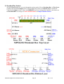
N and M Values:
N: GOP Parameter N (1~256) -- number of frames in GOP
M: GOP Parameter M (0,1,2,3) -- frame distance between reference frames
If M is not 0, then N must be a multiple of M.
If M is 0, then N must be set to 1.
6 <= N < 256 in integer multiples of M for M = 3
4 <= N < 256 in integer multiples of M for M = 2
2 <= N < 256 in integer multiples of M for M = 1
For example,
If N=15 and M=3, the GOP structure is I B B P B B P B B P B B P B B.
If M = 0, the GOP structure is I (encoder will generate I frames only)
If M = 1, the GOP structure is IP
If M = 2, the GOP structure is IBP
If M = 3, the GOP structure is IBBP.
Aspect Ratio: 4:3 (default), 16:9 (wide screen), 2.21:1, or 1: 1(Square PEL).
User Data: Up to 120 (for Program Stream) or 176(for Transport Stream) bytes of text characters can
be inserted into encoded MPEG video/audio stream before or during the encoding time
when this button is clicked with some characters in the editing field next to it: If currently
encoding is in progress, each clicking of this button will insert the text once (multiple
clicking on same text will insert same text multiple times). If currently encoding is not in
MPEGIO2 Application Software Manual
Page 25
Ver. 1.0.2
progress, clicking this button will prepare the characters to be inserted once when MPEG
encoding starts (multiple clicking on the same text will have no effect).
Note special software mechanism is needed to extract the user data inserted from the
MPEG video stream during decoding process.
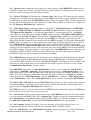
Video PID, Audio PID and UserData PID: These are only applicable when the channel is Transport
Stream Encoder, they define the Video, Audio and UserData Packet IDs in the encoded MPEG stream.
Valid Video /Audio PIDs are 21 ~ 8190 inclusive, valid UserData PIDs are 1 ~ 183 inclusive.
Video PID default is 33, Audio PID default is 34, User Data PID default is 36.
The options under the “Audio Encoding Parameters” group:
Audio Format: Most commonly used is “MPEG1L2” – MPEG1 Layer 2
Sampling Rate: 32K, 44.1K, or 48K Hz: this setting will also be seen in Audio I/O Setup Window.
Bit Rate: Audio encoding bit rate in bits per second:
For Program Stream Encoder:
32000, 48000, 56000, 64000, 80000, 96000, 112000, 128000,
160000, 192000, 224000, 256000, 320000, 384000
For Transport Stream: if format != AC3/MPEG1L1(e.g. if format== MPEG1L2):
32000, 48000, 56000, 64000, 80000, 96000, 112000, 128000,
160000, 192000, 224000, 256000, 320000, 384000
For Transport Stream Encoder: if format == AC3/MPEG1L1:
32000, 64000, 96000, 128000, 160000, 192000, 224000,
256000, 288000, 320000, 352000, 384000, 416000, 448000
If the “DVD Compliant” button is clicked, the Video and Audio settings compliant to DVD creation
will be forced on: Video Bit Rates within 4Mbps ~ 10Mbps, Frame Size 720/704 by 576/480, Audio
Format MPEG1L2, Sampling Rate 48KHz, etc.
The “Reset MPEG IC” hardware reset the MPEG Codec IC: useful to fix encoding/decoding problems.
Note most options can only be set when the channel is not encoding.
Encoding parameters are saved to the MPEGIO2.ini file when the MPEGIO2.exe program exit, and
will be read back when the program starts, unless the command-line switch “-d” is present, or the
MPEGIO2.ini file does not exist.
MPEGIO2 Application Software Manual
Page 26
Ver. 1.0.2
14. Record Video
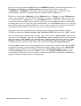
Recording video is to write encoded MPEG data to disk files. The recorded file name, folder, the
recording timer and scheduling etc., are set up in the “Record and Capture Setup” Window.
14.1 Setup Recording
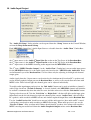
The “Record and Capture Setup” Window can be brought up from either the Setup button on the
Control Window or from the Drop-down Menu-> Setup:
Mouse double-clicking the drive/folder lines inside the “Current Recording Path” listbox will select
the recording folder: the currently selected folder name appears immedaitely above the listbox .
The recording file name needs to be manually typed into the “Recording File Name”edit field – default
name is MPEG#.mpg where “#” is the current channel number. If typed in file name has no .mpg
extension, it will be added automatically when recording starts or when this dialog window re-opens.
Note this file name will not be used for the scheduled recording.
During recording, recording files can be split automatically if “Split at File Size of” or “Split at
Record Time” is ticked and their corresponding field set to some value, the recording will split a new
file if the recording file size or time exceeds the size or time defined. For example:
“Split at File Size of” ticked, its edit field is 4096: split a new file when file size reaches 4GBytes.
“Split at Record Time” ticked, its edit field is 60: split a new file every 1 hour.
If both boxes are ticked and edit fields set then the first condition met will cause a file split.
MPEGIO2 Application Software Manual
Page 27
Ver. 1.0.2
The split file name will be the 1st recording file name without splitting plus an 8-digit number starting
from 00000001, increasing 1 each time a new file is split thereafter .
If the “Split File No. Reset @” is ticked and its edit field is non-zero, then when split file number
reaches this number it will be reset to NULL: the next split file name will be the same as the very 1st file
name before any split started, then next split file name will have the 8-digit number added, …, e.g.:
If this value is set to 10, the split files created will be Rec.mpg, Rec00000001.mpg,
Rec00000002.mpg, …, Rec00000010.mpg, Rec.mpg, Rec00000001.mpg,…
repeatedly. This will create a fixed sequence of recording files to prevent filling-up disk space.
Recording file can also be manually split by clicking the “Split Record File” item from the Drop-down
Menu during recording, or by clicking the “Split” button from the “Record and Capture” window
(See the “Start/Stop Recording” Sub-Section later) brought up by clicking the “Record” button from
the Control Window. Split MPEG files have no gaps between any two ajacent files: binary joining
them will create an MPEG file as if there was no splitting anywhere.
The “Timer” field allows setting a recording timer in minutes --- if not zero, the recording will
automatically stops in Timer minutes.
The “Scheduler” button opens a “Recording Scheduler” window for scheduled recording:
Once setting up the Start date and time, Duration, Repeat etc., clicking the Add button will add a new
recording schedule line to the “Scheduled Recording List” listbox. The edit box “File Name Prefix”
allows a text prefix of <= 20 characters long to be added before the recording date and time to form the
scheduled recording file name(Note the previously described “Recording File Name” field in the
“Record and Capture Setup” dialog is NOT used for scheduled recording) in this format:
File Name Prefix + ChanNum + Date + Time+”.mpg”.
If the “File Name Prefix” field is empty, it will be replaced with string “MPEGIO2”.
Note the “Start Hour” is in 24-Hour format, i.e., 7pm is Hour 19.
Button “Modify” can be used to change an existing schedule line in the list box (highlight the line,
change the fields, then click “Modify”).
Highlight an existing schedule line in the list box then click “Delete” will remove a schedule.
Ticking the “UTC” box will use “Coordinated Universal Time” in the scheduled file name, otherwise
local time will be used in the file name.
MPEGIO2 Application Software Manual
Page 28
Ver. 1.0.2
Ticking “No Date in FileName” or “No Time in FileName” will exclude Date or Time (or both) when
forming the scheduled recording file name.
When scheduled recording starts, it will overwrite an existing file with the same name if that exists.
Note at schedued time scheduled recordings can only start if the program MPEGIO2.exe is running.
When the scheduled time arrives, if the channel is already recording(e.g. through manual start) the
scheduled recording will be ignored.
14.2 Start/Stop Recording
The “Start Record” selection from the Drop-down Menu can start recording for a single channel.
To start recording multiple channels simultaneously, use the “Record and Capture” window by
clicking the “Record” button
on the Control Window:
In this window, ticking multiple channels then clicking the Record button will start recording on those
channels ticked. Similarly, Pause, Split, Stop, Streaming (as part of Start Recording) and Capture
(Still Image) can all be done on multiple channels here. Stopping, Pausing or Splitting single channel
recording can also be done from the Drop-down Menu. Existing file names will be overwritin silently.
15. Stream Video
Using User Datagram Protocol(UDP), MPEGIO2 channels can stream out encoded or decoded MPEG
video/audio to any IP client that can receive MPEG video, such as the free VideoLan software, Amino
Set-top box, etc.
To set up video streaming parameters, open the “MPEGIO2 Stream Setup” window from either the
“Setup” button on the Control Window, or from the Drop-down Menu->Setup:
MPEGIO2 Application Software Manual
Page 29
Ver. 1.0.2
In order to receive streamed out MPEG video from MPEGIO2 channel, a network client must have its
IP Address, Port Number and Multicast/Unicast settings specified in this window. The
“SendBufSize”, “RevBufSize” fields indicate the output and input buffer sizes in Kbytes of the
network sockets created for streaming, 0 inidcates using the default 128Kbyte size.
IP addresses can be either “Multicast” (tick the Multicast box) or “Unicast” (clear the Multicast box):
address range 224.0.0.0 ~ 239.255.255.255 normally are counted as “Multicast” addresses, while the
rest will be counted as “Unicast” ones. If a valid Multicast address is used, the streamed video can be
received by any host machines (PCs or non-PCs) having access to that Multicast address, and multiple
streaming clients can receive the same video simultaneously. If a valid Unicast address is used, only the
host machine that has that particular IP address can receive the streamed video, and only one playback
client on that machine (PC or Set-top box) can actively receive that video at any time.
To stream across wide area network such as Internet, the receiving end must configure its router’s
TCP/IP port through the Network Address Port Translation (NAPT) function using “UDP” protocol.
To start streaming video encoded from a channel, tick the box under the “Start Stream” button on the
same line as the “Chan No.”, then click the “Start Stream” button: multiple channels can be ticked and
started streaming encoded MPEG video simultaneously. Similarly, ticking the boxes under the “Stop
Stream” button then clicking the button can stop streaming multiple channels. Starting or stopping
streaming encoded video for a single channel can also be done through the Drop-down menu.
Streaming MPEG video can be started independent of (as shown here) or together with starting MPEG
recording or decoding: to start streaming simultaneously when recording starts, use the “Record and
Capture” dialog window described previously under the “Start/Stop Recording” Section. To start
streaming decoded (previously encoded) MPEG video, see the “Playback MPEG Video” Section
described later in this manual. Once a channel is streaming, its IP address, port number and Multicast
properties cannot be changed until the streaming stops.
MPEGIO2 Application Software Manual
Page 30
Ver. 1.0.2
16. Capture Still Images
Still images can be captured from MPEGIO2 channels in BMP, JPG, GIF(under WinXP only),
TIFF(under Win7 or above), or PNG format. Each image file is 720X576 pixels for PAL or 720X480
pixels for NTSC input signal plus some plus or minus adjustment (described later in this section). Image
capturing is completely independent of MPEG video Encoding, Decoding or Video Preview process:
image can be captured during or prior to video encoding, streaming, decoding, regardless the Video
Preview window is turned on or off. Image capture parameters setup is in the lower part of the
previously described “Record and Capture Setup” window (in Section Record Video->Setup
Recording) under the heading “Capture Still Image”:
Clicking the button “Set Capture Folder:” will set captured image files’ folder to be the currently
displayed folder as under the “Current Recording Path” at the upper part of the window: this can be
totally different(by left-mouse double-clicking inside the directory list box) from the folder set to hold
recorded MPEG video files. When this button is clicked, the capture image folder name will appear in
the read-only edit field beneath the button.
Use the “Capture Format” combo box to select image format, note under WinXP and under Win7 the
3rd format will be either .GIF or .TIF respectively.
The “Start Serial No.” edit box defines the starting numerical number the subsequent image capturing
will use as part of the image file name, which is formed as 3 parts with underscores ‘_’ in between:
“Capture File Name” String _Channel Number as 2-Digit Number _Serial No. as 6-Digit Number.
Each time a new image file is captured, the Serial Number increases its value by 1 to be used for the
next capture, unless its value is re-defined in this window.
MPEGIO2 Application Software Manual
Page 31
Ver. 1.0.2
The “Bright”, “Contrast” and “Saturate” fields can be used to adjust the colour parameters of the
captured image without affecting colours on video preview and MPEG recording.
The “Follow Preview” button set the “Bright”, “Contrast” and “Saturate” values to be the same as the
Video Preview’s “Bright”, “Contrast” and “Saturate” values set in the “System Setup” window.
The “Cut off Bottom Lines” field indicates number of lines to be cut off from the bottom of the
captured image: if this is 10 then a PAL input signal channel will capture images at 720X566 pixels
instead of 720X576 pixels, while an NTSC input signal channel will capture images at 720X470 pixels
instead of 720X480 pixels. Set a non-zero cut off value can get rid of some of the noise lines sometimes
appearing at the bottom of the captured (and previewed) video frame. This field defaults to 0.
The “Pause Preview” field only appears on Windows 7 or above, used to temporarily pause video
preview during still image capture, so that to avoid black stripes on some Intel Chipset (Q67 etc.)
motherboards. This normally can be cleared as default.
The “Deinterlace” field selects software deinterlacing applied on the captured image, default is None,
but can be selected as Copying Odd lines to Even lines, or Copying Even lines to Odd lines, that can be
used to improve on edge fuzziness on images captured from video with very fast moving objects.
The “Width +/-:” and “Height +/-:” fields allow plus or minus pixel adjustment (max. +/- 200) on the
captured image size. These adjustment are applied after the “Cut off Bottom Lines” operation, and
they only shrink or expand the captured image size but do not cut off or add pixels. Default are zeroes.
The PAL or NTSC signal format of an MPEGIO2 channel is automatically decided according to the
“Preview TV Signal” field in the Video I/O Setup dialog, the “TV Signal” fields in “System Setup”
and “MPEG Encoding Setup” dialog windows --- these 3 fields show the same value, as described in
detail in the previous Sections.
To capture image on a single channel, pop up the Drop-down Menu by right-mouse clicking in the
channel’s area in Video Window then select “Capture Image”. Single channel image capture can also
be triggered by voltage pulse on the “Digital I/O Pins”: see the “Digital Input/Output Pins” section
later for setting up automatic image capture through Digital I/O pin configuration.
To manually capture images on multiple channels simultaneously, use the “Capture” button
of the “Record and Capture” dialog window opened by clicking the Record button
Control Window:
on the
.
Here each click of the “Capture” button will capture still images for all those selected “Chan#” channels.
MPEGIO2 Application Software Manual
Page 32
Ver. 1.0.2
17. Playback MPEG Video (Decoding)
Although video recorded by MPEGIO2 can play back on most software video players, playing on
MPEGIO2 hardware offers low PC resource (CPU/RAM) consumption even on simultaneous multichannel playback, simultaneous output to external TV monitors, and no need for any software MPEG
Codec. MPEGIO2 also allows playing back one MPEG file as multiple images within one or two
channels simultaneously.
During playback, the recorded MPEG data is decoded by the Codec IC on the card; the decoded video
appears simultaneously on PC screen in the Video Preview window as the “VIN1” signal source, and on
the MPEG Decode ports and Loopback Output ports (RCA and S-Video) of the Breakout Box.
Decoded video can also be streamed over IP network, same as streaming encoded video. Note on the
Breakout Box, the “MPEG Decode ports” show the decoded video as full screen without any overlay
(if overlay is created), while the “Loopback Output ports” show the decoded video in any Video Sub
Window the VIN1 Video Source is connected to as its Input Source, together with any Overlay created:
this is because internally the MPEG decoding output coming out of the MPEG Codec IC is physically
connected to the VIN1 Video Input Source: this source can be connected to one or more Sub Windows;
so if you wish, you could display two or more identical decoding video images simultaneously on the
PC screen and on the Loopback Output ports of the Breakout Box. You can also real-time convert the
decoded video to a different MPEG format on the matching channel and stream it out simultaneously.
To setup and start/stop/pause decoding MPEG video, open the “Playback Setup” window by clicking
the “Play” button
on the Control Window, or from the Drop-down Menu->Play Video:
This window can also be opened from the Drop-down Menu->Setup->Playback Setup.
The “Encoder Type” selection decides the decoded MPEG encoding type: channel with Program
Stream Encoder Type can only decode MPEG data encoded by Program Stream encoder, channel with
Transport Stream Encoder Type can only decode MPEG data encoded by Transport Stream encoder:
mismacthed Encoder Type will result in no video or wrong content being decoded.
The “TV Signal” combo box is the same as in the “Preview TV Signal” field described previously in
the “Video I/O Setup” dialog window. The current channel’s TV Signal type (PAL or NTSC) must
match the MPEG to be decoded: MPEG video encoded as PAL must be decoded when channel has PAL
TV Signal type, video data encoded as NTSC must be decoded when channel has NTSC TV Signal type.
The “Stream Type” combo box selects the decoded MPEG video’s Stream Type:
MPEGIO2 Application Software Manual
Page 33
Ver. 1.0.2
MPEG4_ES: MPEG4 Elementry Stream (Video only);
MPEG4_PS: MPEG4 Program Stream;
MPEG4_TS: MPEG4 Transport Stream;
MPEG2_PS: MPEG2 Program Stream;
MPEG2_TS: MPEG2 Transport Stream;
MPEG1_SS: MPEG1 System Stream;
VES: Video Elementry Stream(Contains only Video, no Audio encoded);
Auto Select: Automatically Decide by MPEGIO2 Channel Hardware.
Ideally, the decoded “Stream Type” should match the corresponding set up when the MPEG video was
encoded, as the combined settings in the “Encoder Type”, “MPEG Type” and “Mux Type” fields in
the “”MPEG Encoding Setup” dialog
as described in the
previous “MPEG Encoding Parameters” Section. However, when the MPEG video file’s “Stream
Type” is unknown, the “Auto Select” can be selected to let MPEGIO2 hardware detect its “Stream
Type”: note this could cause software crash if the presented MPEG data is invalid or un-recognizable by
the MPEGIO2 hardware. In general, MPEGIO2 can safely decode all MPEG video encoded by itself,
by Inventa’s MPEGIO, MPEGIOPro, USBOSDM2, USBMPEG2-Box, and generic MPEG2, MPEG1
video files encoded by other hardware or software encoders. MPEG4 video encoded by other hardware
or software encoders are not guaranteed to be decoded properly.
MPEG video file name can be selected by typing in the full path or clicking the “Select File” button to
choose from folders.
The “Loop” check box allows repeatedly decoding the file (re-decode from the beginning when file
end is reached) until playback is manually stopped.
The options “Pause” and “Stop” are enabled when Play is successfully started: they will pause playing
temporarily or stop playing completely. “Pause” or “Stop” can also be initiated from the Drop-down
Menu once Play is successfully started.
Ticking the “Stream Out” box will stream the decoded MPEG video over the Network IP Address +
Port + Multicast type as setup in the “MPEGIO2 Stream Setup” dialog window described in Section
“Stream Video” previously.
A channel cannot play video while is encoding and vice versa. However, played video in a channel can
be output to its matching channel on the same MPEGIO2 card to be encoded there simultaneously, by
setting the playing channel’s video output to be the matching channel’s video input: this way a decoded
MPEG file can be simultaneously encoded with a possibly different MPEG format, or even a different
PAL/NTSC TV signal type, in real-time, into a new file or network stream address or both.
When a channel is not encoding and streaming, using mouse to drag-and-drop an MPEG file (name
must have case-insensitive extension “.mpg”) into the Video Preview Window area of that channel will
start playing that file: if the channel is currently playing the current playing will stop and the newly
MPEGIO2 Application Software Manual
Page 34
Ver. 1.0.2
dropped file will start playing. Note this “drag-and-drop” playing will always use the “Auto Select” as
“Stream Type”, so Video Only files (VES Stream Type) will not play properly in this way.
18. Digital Input/Output Pins
Each MPEGIO2 channel has 4 “Digital I/O” pins, located at the Top Layer of the Breakout Box,
together with a common Ground pin:
Connecting an external device between a Digital I/O pin and the ground pin allows the external device
to receive High/Low signal from MPEGIO2 software, or to send High/Low signal to MPEGIO2
software, therefore be controlled by MPEGIO2 or to control MPEGIO2’s operation.
MPEGIO2 Digital I/O pins treat DC voltage -0.5V ~ +0.3V as Low, +0.7V ~ +5.5V as High Status,
each I/O pin can sustain 25mA max. current. Voltage from old batteries are not suitable as input trigger
since they cannot supply enough current.
To use Digital I/O pins, open the “MPEGIO2 Digital I/O Setup” window by clicking the “Setup”
button on the Control Window then select “Digital I/O Setup”:
MPEGIO2 Application Software Manual
Page 35
Ver. 1.0.2
In this window, the “Digital I/O Pin” combo box indicates the 4 Digital I/O pins a channel has; the
“Pin Direction” indicates either Input or Output direction a pin is configurated as: Input pins can
receive High/Low voltage signal sent by external devices connected to them, while Output pins can
send High/Low voltage signal to external devices. By default all pins are configued as Input, but user
can change any pin’s direction by selecting the “Pin Direction” combo box value.
When a Digital I/O pin is set as Input direction, voltage High/Low change on this pin can send
notification to the MPEGIO2 software automatically: “Actions” can then be taken in response to the
pin’s status change. Ticking the “Enable Notify” check box then selecting some lines inside the
“Actions” list box, a pin’s status change will cause those selected “Actions” to happen, such as starting
or stoping recording, streaming or capturing image. The “Input Pin Value Change” combo box selects
either “Low to High” or “High to Low” voltage change on this pin that will cause the selected “Actions”
to happen. The button “Clear Settings” is to clear all “Status Change to Actions” setup. Note the
“Toggle” actions mean the same voltage pulse on the pin will 1st start the operation, then the next pulse
will stop the operation: e.g., “Toggle Overlay” means the 1st voltage pulse will enable the overlay if the
overlay is currently disabled, then when the 2nd voltage pulse happens the overlay will be disabled again.
Note: Do Not trigger “Capture Image” too quickly on a channel: this could cause software crash: e.g.
setting “Capture Image” for both Low to High and High to Low on the same pin should be avoided.
When a digital I/O pin is set up as “Output” direction, the previously disabled combo box “Pin Value”
becomes enabled: now manually selecting this Pin Value as “High” or Low” will change the voltage
(“High” will produce approx. +5 Volt, “Low” will drop it to 0 Volt) at the pin accordingly --- if
external device is connected the device will receive this voltage change:
More flexible Digital I/O control can be achieved by calling relevant functions in the MPEGIO2 SDK:
see the “Digital I/O Functions” Section in the “MPEGIO2 SDK User Manual” for more details.
MPEGIO2 Application Software Manual
Page 36
Ver. 1.0.2
19. Other Drop-down Menu Selections
When the Drop-down Menu is brought up by right-mouse clicking the Video/Control Window, its top
line always indicates a channel number: if right-mouse was clicked inside a channel’s video area in the
Video Window, the channel number will indicate that channel; if right-mouse was clicked on the
Control Window, the channel number will indicate the previously mouse clicked channel inside the
Video Window. When a menu item is selected from the Drop-down Menu, its operation is only on the
channel as the Drop-down Menu’s top line indicates : e.g., “Start Record” will only record MPEG
video for this channel, “Capture Image” will only capture this channel’s video image, etc.
Overlay Off: Hide all defined Overlay Items for this channel, same as “Disable Overlay”.
Sub Win Common Pos: Arrange the 4 Video Sub Windows according to some Common Positions.
Pause Audio Preview: Toggle this channel’s Audio Preview on/off if it is previewing audio.
Status Off: Hide all Preview Text display, such as the “0:PAL” at the top of this channel’s video.
Single-Chan Preview/All-Channel Preview: Displaying one or all channels in the preview window.
Centre Windows: Set the Video & Control Windows to be at screen centre with default sizes.
Maximize: Toggle the Video Window to be Full-Screen or not, same as left mouse double-click.
Minimize: Toggle the Video & Control Windows to be a Taskbar icon
Exit: End the MPEGIO2.exe application program.
About MPEGIO2…: Display About MPEGIO2 Dialog.
or normal windows.
20. Command Line Parameters
At start up, MPEGIO2.exe application program accepts some command-line-parameters so that it can
enter certain operation mode once started. Command-line-parameters are supplied in the form of:
–Cmd chanNum [Value]
Where Cmd is a single letter (Case Insensitive) command, this field must always be supplied;
chanNum is the numerical channel number(0 for 1st channel), this field must always be supplied;
Value is the value needed for Cmd, this is an optional field depending on Cmd’s content.
MPEGIO2 Application Software Manual
Page 37
Ver. 1.0.2
Currently supported Command-line-parameters are:
-r chanNum: start recording on channel “chanNum”.
-s chanNum: start streaming on channel “chanNum”.
-f chanNum filename: use filename as recording file name for “chanNum”, note if
filename contains spaces the entire string must be double-quoted.
-p chanNum pathname: use pathname as recording path name for “chanNum”, note if
pathname contains spaces the entire string must be double-quoted.
-t chanNum timerVal: use numerical value timerVal as recording timer (in Minutes) for “chanNum”.
-n NoCodec: Setting 1’s in any of the lowest 16 binary bits in numerical value “NoCodec” indicates
that channel will not initialize its MPEG Codec IC(therefore cannot encode/decode).
-d: start the program with default values for all parameters
(see next section on default parameter values), ignoring the MPEGIO2.ini file.
-v OnOff: start the program with Video Preview Window On (OnOff=1) or Off (OnOff=0).
-u: start the program in Full Screen mode.
-m: start the program in minimized mode.
-k: start the program muting PC speakers for all channels’ audio preview.
-g: TVSignal: TVSignal must be 1 (NTSC) or 2 (PAL), indicating the default TV Signal Type used
when no signal is available at all input sources used by any Sub Window for a channel.
If -g is not supplied and no signal is available at all input sources used by any Sub
Window for a channel, the Windows’ Regional/Country/Language setup (in Windows’
Control Panel) will decide if NTSC or PAL is used as the default TV Signal Type: USA,
Japan, Canada etc. country setting will use NTSC, Australia, UK, etc. will use PAL.
-a: DMARamMode: DMARamMode must be 1 or 2 to indicate the DMA RAM mode used during
Video Preview and Image Capture for Windows 7 or above, ignored on WinXP:
Value 1 is suitable for graphics chipset that can do YUV to RGB colour space conversion,
such as ATI Radeon: Mode 1 is more efficient than Mode 2;
Value 2 is useful for graphics chipset that cannot do YUV to RGB colour space
conversion, such as Intel Q67 chipset graphics cards or NVidia GS8400;
Default is 0: the SDK detects the graphics card chipset’s colour space conversion
capability then chooses mode 1 or 2 automatically.
Some examples:
MPEGIO2.exe –r 0 –f 0 record0.mpg --- start recording on channel 0 to file record0.mpg
MPEGIO2.exe –s 0 –d --- start streaming on channel 0, do not read MPEGIO2.ini file at start
MPEGIO2.exe –r 0 –r 1 –s 0 –s 1 --- start recording and streaming on channel 0 and channel 1
MPEGIO2.exe –r 0 –p 0 C:\\chan0 -f 0 rec.mpg --- record on channel 0 to file c:\chan0\rec.mpg
MPEGIO2.exe –n 9 --- Disable MPEG Codec at Channel 0 and 3 so these 2 channels cannot encode/decode
Note: command-line parameters will override the MPEGIO2.ini settings if they conflict.
21. Default Parameter Values
MPEGIO2.exe uses initialization file “MPEGIO2.ini” to store values for its user-definable parameters:
each time MPEGIO2.exe exits, values of these parameters are saved into MPEGIO2.ini file which
resides in the same folder as the MPEGIO2.exe program ---- Make sure the user account logged into
MS Windows has Write permission to the Folder (usually C:\Program Files\Inventa\MPEGIO2) the
MPEGIO2.exe resides, otherwise the MPEGIO2.ini file cannot be created. Each time when
MPEGIO2.exe program starts it uses this file’s contents to assign values to its parameters. If the
MPEGIO2.ini file does not exist (such as when MPEGIO2.exe is started on a PC for the 1st time), or if
the Ctrl Key is held down when MPEGIO2.exe starts, or if the “–d” command line parameter is
supplied, the software will use the following default values for its parameters:
MPEGIO2 Application Software Manual
Page 38
Ver. 1.0.2
Video I/O Parameters:
Sub Window Common Position: 4 SubWins (Split with each SubWin occupying 1/4 of the video frame)
Sub Window Cropping :
For PAL: Left=15, Top=10, Width=720, Height=576
For NTSC: Left=15, Top=12, Width=720, Height=480
Sub Window Enable: Yes
Sub Window Input Source: SubWin0=VIN0, SubWin1=VIN1, SubWin2=VIN5, SubWin3=VIN3
(Note VIN1 is MPEG decoding video output, VIN5 is SVideo Socket)
Sub Window Freeze: No
Sub Window Border: No
Sub Window Popup: Yes
Sub Window Zoom: No
Sub Window Border Blink: No
Sub Window Mirror: No
VIN 4 Auto Crop: No
VIN 4 Horizontal Start/Stop: 0/0
VIN 4 Vertical Blank Start/Stop: 0/0
Auto Switch PAL/NTSC: No
7.5IRE Black Level: Yes if “Default TV Signal Type” is NTSC and Country Code is not Japan, otherwise No
Input ColourBar: No
Background Colour: Black
Blank Colour: Blue
Video Loss Indication: No Action
White Peak Detect Threshold: 216 (for VIN 0 ~ VIN 3)
Auto AGC (Gain): Enabled (for VIN 0 ~ VIN 3)
Manual AGC Gain Value: 240 (for VIN 0 ~ VIN 3)
AGC Normal Maximum Gain: 3 (for VIN 0 ~ VIN 3)
AGC White Peak Gain: 1 (for VIN 0 ~ VIN 3)
VIN 4 Luma AGC : Enable
VIN 4 Chroma AGC : Enable
VIN 4 WP(White Peak Detection) Disable: No
VIN 4 LP(Luma Peak Detection) Disable: No
PatchROM: Cleared
Output1 BlankLevel: 42
Output2 BlankLevel: 42
Audio I/O Parameters:
No Init on Startup: No
Preview Auto On: No
-6dB on Input: No
Mute: No
Left Gain: 79
Right Gain: 79
Audio Play Buffer Nums: 4
Audio DMA Buffer Nums: 0
Audio Sampling Rate: 32KHz
Audio Preview On: No
Preview Use WaveOut API: Yes
Audio Input from Matching Channel on this Card: No
Audio Output to Matching Channel on this Card: No
Audio Source for Speakers Output: This Channel’s Audio
Record and Capture Setup:
Current Recording Path: C:\
Timer: 0(No Recording Timer)
Recording File Name: MPEG#.mpg (# is the channel number)
Split Recording File: No
MPEGIO2 Application Software Manual
Page 39
Ver. 1.0.2
Overlay Item Parameters:
Font: Times New Roman, Regular, Size 14, Script Western
Start X/Y: 0, 0
Foreground Colour: Red
Background Mode: Transparent
Alpha: None
Blink: None
Disable Overlay: No
Timer Format: Time Only
MPEG Encoding Parameters:
Encoder Type: Program Stream
MPEG Type: MPEG2
Horizontal Size: 720
Vertical Size:576 if PAL, 480 if NTSC
Max. Bit Rate: 6.00 Mbps
Ave. Bit Rate: 6.00 Mbps
CBR: No
Scene Change Detect: No
VOB Format: No
Black Screen: No
Horizontal Mask: -1
Vertical Mask: -1
Frame Rate: 25 if PAL, 29.97 if NTSC
Closed GOP: No
GOP Structure: N==15, M==3
Aspect Ratio: 4:3 for MPEG2 and MPEG4, 1:1 for MPEG1
MPEG Encoding Audio Bit Rate: 384 Kbps
MPEG Encoding Audio Sampling Rate: 32KHz
MPEG Encoding Audio Format: MPEG1 Layer 2
Video PID: 33
Audio PID: 34
UserData PID: 36
User Data: None
Video Streaming Parameters:
IP Address: 127.0.0.1 (local PC)
Port Number: 5000
Multicast Streaming: No
SendBufSize: 0 (Use 128Kbytes)
RecvBufSize: 0 (Use 128Kbytes)
Image Capture Parameters:
Capture Folder: C:\
Start Serial No.: 0
Image Type: Bitmap (.bmp)
Image Capture File Name: IMAGE
Bright: 128, Contrast: 64, Saturate: 64
Cut off Bottom Lines: 0
Pause Preview during Still Image Capture(Win7 only): No
Width +/-, Height +-: 0
Digital I/O:
Pin Direction: Input
Pin Value: Low
Enable Notify: No
MPEGIO2 Application Software Manual
Page 40
Ver. 1.0.2
System Setup:
Start with Video Preview: Yes
Confirm on Exit: Yes
Channels per Row inside Video Preview Window: 0 (All channels on one row)
Show Preview Status: Yes
Monitor Number used for Video Preview: the Primary Monitor Number
Status Text1 X/Y: 0/0
Status Text2 X/Y: 0/0
Status Text2 Shift: 0
Video Preview Src Clip X/Y/R: 0, B: -12
Confirm on Exit: Yes
ColourBar: No
Text Font: Times New Roman, Regular, Size 14(WinXP)/36(Win7), Colour Red, Script Western
Preview Deinterlace(Win7 only): Odd to Even
Preview Colour Bright/Contrast/Saturate: 128/64/64
22. Hotkeys
Control Window or Video Window:
When focus is on either Window, pressing one of these case-insensitive keys will execute these functions:
S:
R:
P:
E:
O:
X:
Setup Button: Display Setup Menu:
Record Button: Display the “Record and Capture” Dialog Window
Play Button: Display the “MPEGIO2 Playback Setup” Dialog Window
Stream Button: Display the “MPEGIO2 Stream Setup” Dialog Window
Overlay Button: Display the “MPEGIO2 Overlay Setup” Dialog Window
Exit Button: Exit the MPEGIO2 Program.
Drop-down Menu:
Case-insensitive keys in Drop-down Menu same as mouse-selecting the corresponding menu item:
A:
About MPEGIO2
C:
Capture Image
E:
Start/Stop Stream
I:
Split Record File
M:
Maximize
N:
Minimize
R:
Start/Stop Record
U:
Pause/Resume Record
V:
Pause/Resume Audio Preview
P:
Play/End-Play Video
O:
Overlay Setup
W:
Centre Windows
X:
Exit MPEGIO2.exe
Y:
Pause/Resume Play
MPEGIO2 Application Software Manual
Page 41
Ver. 1.0.2
Video Window Mouse Clicking:
Left Mouse Double-Click: Toggle between Full Window and Normal Window Display.
Ctrl + Left Mouse Double-Click: Toggle between “One Chan Mode” and “All Chan Mode”.
Shift + Left Mouse Single-Click: Zoom from the mouse point if “Zoom” is enabled for the Channel,
---- See Video I/O Setup Dialog Window for Zoom ---Left Mouse Click without Shift held-down to Cancel Zoom.
23. Special Applications
With its unique design architecture, MPEGIO2 can create some special applications, examples include:
(1) Encode PAL input to NTSC MPEG video or vice versa, this also real-time convert PAL/NTSC input to
NTSC/PAL output on the Breakout Box Ports (RCA & SVideo): on the “Video I/O Setup” dialog, set
the “TV Signal on This Input Src” combo box to the TV signal type different from the input signal
will accomplish this. Note if video preview is garbled after manually setting the “TV Signal on This
Input Src”, clear then tick the “Preview Video” check box on the Control Window usually can fix it.
(2) Simultaneously encode and stream two different format and/or sizes MPEG video from the same input:
configure one Sub Window’s video source as from this MPEGIO2 channel’s matching channel will
accomplish this --- on the “Video I/O Setup” dialog, select a Sub Window’s “Video Input Source” as
“VIN 4 SVideo”, then tick the “VIN 4 Input from Matching Chan”. For example, this can
simultaneously encode Program Stream and Transport Stream video, or MPEG2 and MPEG4 video
from the same video input, to two separate MPEG files and/or IP streams.
(3) Play and convert previously encoded MPEG video (by MPEGIO2 or other hardware/software) into a
different format MPEG video: as in (2), set up a Sub Window’s video source as from the matching
channel, then play some recorded video on the matching channel while simultaneously encode a
different MPEG format on this channel: Overlay Text/Graphics can be added on the encoded video.
(4) Silently trigger recording/streaming/capturing on external signal using the “Actions” on the “Digital
I/O Setup” dialog: after setting up actions “Start Recording”, “Start Streaming”, “Capture Image” etc.,
minimize the MPEGIO2, or re-start the program as minimized.
(5) Simultaneously play/stream/convert the currently encoded video using third-party software: running
VideoLan(vlc.exe), SMPlayer(MPlayer), ffplay.exe(ffmpeg), DiVX Plus Player, Total Video Player,
Elecard MPEG Player etc. side-by-side with MPEGIO2.exe, the MPEG video can be processed in
many different ways inc. streaming, conversion, editing etc. in real-time while the hardware is encoding.
MPEGIO2 Application Software Manual
Page 42
Ver. 1.0.2
24. Technical Discussions
1. Under Windows XP, avoid starting MPEGIO2.exe while other Video Overlay application is
displaying video: programs such as MediaPlayer, VideoLan etc. will grab DirectDraw surface
resulting in MPEGIO2.exe unable to start Video Preview Window: Start MPEGIO2.exe first then
start these programs will be OK. Note on Windows 7 or above MPEGIO2.exe can start any time
regardless other applications have been displaying video preview or not.
2. When Pause/Resume recording to MPEG files, please note if the paused period (the time between
pause and resume recording) is short (e.g., < 20 sec), then some software MPEG video players such
as VLC.exe, Windows MediaPlayer, etc. will also pause when their play reaches the paused point
inside the MPEG file, while other software video players such as “E.M. Total Video Player”
(http://www.effectmatrix.com/), MediaPlayer Classic(http://mpc-hc.sourceforge.net/), GOM Player
(http://www.gomlab.com/eng/), SMPlayer(MPlayer), KMPlayer, etc. will play smoothly over the
paused point without obvious delays. Note MPEGIO2 itself will always play smoothly over any
paused points without delays in its recorded files regardless how long or short the paused time was.
3. Screen Capture with Live Video Preview: live video previewed by MPEGIO2 can be successfully
captured under Windows7 or above (but not on WinXP) when Ctrl+“Print Screen” keys are pressed.
4. File folders must have Write Permission: all folders holding the MPEG recording files, still image
files and MPEGIO2.ini file must have Write Permission for the user, or these files cannot be
created: e.g. on Windows 8 C: drive’s root directory might not be writable so use other folders to
save MPEG and image files. Also on Windows 8 by default the MPEGIO2 program folder
C:\Program Files\Inventa\MPEGIO2 folder is not writable: this must be changed manually to have
write permission for the current user so that MPEGIO2.ini file can be written each time
MPEGIO2.exe exit.
5. MS Windows’ “Power Options” should not turn off hard disk: during MPEG recording if the MS
Windows’ “Power Options” (under “Screen Saver” settings) include turning off hard disk this must
be disabled, otherwise recording can fail and hang MEGIO2.exe when the hard disk is turned off.
6. Install MPEG2 playback Codec filters: on Windows XP and Windows 7 the Start.bat program
automatically registers MPEG2 playback codec, while on Windows 8, this must be done manually
by running the “RegFilters.bat” from the MPEGIO2 Program Group as “Administrator”. Without
properly registering MPEG2 playback codec the Windows MediaPlayer cannot play MPEG2 files.
MPEGIO2 Application Software Manual
Page 43
Ver. 1.0.2
25. MPEGIO2 Hardware Specifications
Host Interface: 1X PCI-Express Card
Maximum Power Consumption: < 10 Watts
Video Input: 6 X Composite (RCA), 2 X S-Video (4-Pin Mini-DIN)
Video Output (for Real-time Monitoring and MPEG Decoding): 4 X Composite (RCA), 2 X S-Video
Audio Input: 4 X Line-in 3.5mm Stereo Mini Socket
Audio Output: 4 X Line-out 3.5mm Stereo Mini Socket
Encoded/Decoded Video Formats: MPEG-1, MPEG-2 MP@ML, MPEG-4 Simple Profile@L1,L2 & L3, with extensions to full-D1,H.263.
I, IP, IBP, IBBP Frames. PES & ES. Support Both Program Stream and Transport Stream Encoding & Decoding
Constant Bit Rate (CBR) and Variable Bit Rate (VBR) Encoding
Video 4:2:2 to 4:2:0 Conversion
Video Inverse telecine (3:2 pulldown)
Video Encoding Frame Rates: 23.976fps, 24 fps, 25fps, 29.97fps, 30fps, 50fps, 59.94fps, 60fps
Video Encoding Bit Rates: 128 Kbps ~ 15.00 Mbps
Video Encoding / Decoding Resolution in Pixels: Horizontal 176, 352, 480, 528, 544, 640, 704, 720,
Vertical 120, 144, 240, 288, 480, 512, 608, 576
Video Encoding Aspect Ratio: 4:3, 16:9(Wide Screen), 2.21:1, 1:1 (Square Pels)
Audio Encoding Format: MPEG1 Layer 1, Layer 2, Layer 3(MP3), MPEG-2 audio, AC3, AAC, G.711, G.723, G.726, G.729
Audio Sampling Rates: 32KHz, 44.1KHz, 48Khz
Audio Encoding Bit Rates: 0 to 448Kbps, inc. 64Kpbs, 128Kpbs, 160Kbps, 192Kbps, 224Kbps, 256Kbps, 320Kbps, 384Kbps. etc.
Digital Input/Output Pins: 8 Pins (4 for each Channel): each Pin responds to -0.5V ~ +0.3V as Low Status, +0.7V ~ +5.5V as High Status,
with maximum current 25mA per Pin, and a total current sourced by all Pins limited to 160mA. 1 Ground Pin Common for All I/O Pins.
PCIe Card Dimension: Length 230mm, Height 145mm
MPEGIO2 Application Software Manual
Page 44
Ver. 1.0.2