1
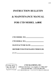
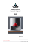
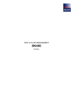
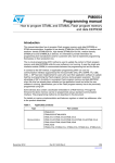
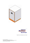
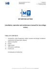
FAST & FLUID MANAGEMENT srl
A Unit of Idex Corporation
Shaker SO-300
USER MANUAL
FAST & FLUID MANAGEMENT Srl
A Unit of IDEX Corporation
Via Pelizza da Volpedo, n° 109/111
20092 Cinisello Balsamo (MI)
ITALY
Tel.
: +39 02 66091.1
Fax
: +39 02 66091550
Web : www.fast-fluid.com
FAST & FLUID MANAGEMENT srl
A Unit of Idex Corporation
INDEX
1. INTRODUCTION............................................................................................................. 2
2. INTELLECTUAL PROPERTY RIGHTS........................................................................... 2
3. TECNICHAL SPECIFICATIONS ..................................................................................... 2
4. WARRANTY TERMS AND CONDITIONS ...................................................................... 3
5. GENERAL DESCRIPTION.............................................................................................. 3
6. SAFETY RULES ............................................................................................................. 3
7. RESIDUAL RISKS .......................................................................................................... 5
8. INSTALLATION REQUIREMENTS................................................................................. 6
9. KEYBOARD .................................................................................................................... 7
10. HOW TO OPERATE ..................................................................................................... 7
11. LOADING THE CAN INTO THE MACHINE .................................................................. 8
12. ACOUSTIC WARNINGS ............................................................................................... 8
13. SAFETY ........................................................................................................................ 9
14. MAINTENANCE AND CLEANING ................................................................................ 9
15. FUNCTIONAL DIAGRAM 100 – 115 - 230V ............................................................... 12
16. ELECTRIC BOX AND WIRING DIAGRAM 230V – 50Hz............................................ 13
1
FAST & FLUID MANAGEMENT srl
A Unit of Idex Corporation
ENGLISH
1. INTRODUCTION
SO300 by FAST & FLUID MANAGEMENT is the result of the most recent technology in high speed paint
mixing. Your SO300 by FAST & FLUID MANAGEMENT is a sturdy and effective shaker; its way of operating
and its design show all quality of a careful engineering work on the product.
To appreciate fully and protect your investment, we suggest that you take some time to read this manual.
As usual, FAST & FLUID MANAGEMENTwill support you post sales assistance service.
The few maintenance operations, which will be mentioned further on, shall be carried out regularly.
FAST & FLUID MANAGEMENT will not be held responsible for any damage or accident
which might happen because of failure to respect the regulations set, or because of
wrong use or of maintenance carried out without the standard safety rules being
followed, as explained further on.
SO300 shaker must not be switched on if it has not been earthed through one or both the
earthing connection points (socket and/or earthing bolt).
2. INTELLECTUAL PROPERTY RIGHTS
Statement on Intellectual Property Rights.
The information contained in this manual is based on data which belong to FAST & FLUID MANAGEMENT.
This manual has been drawn up expressly for assistance in the use and general maintenance of SO300 shaker.
The publication of this info does not give any allowance for reproducing or using this manual for other than installation, use
or maintenance.
No part of this manual can be reproduced, translated or filed (neither on computer) in any form or by any means without
written authorization by a FAST & FLUID MANAGEMENT officer.
3. TECNICHAL SPECIFICATIONS
EN 292 Part 1 and 2: 1991
EN 418: 1992
EN 60204 Part 1: 1997
EN 954 – 1: 1996
EN 1088: 1995
EN 294: 1992
EN 953: 1997
PrEN 12757-1
Safety of machinery - Fundamentals, general principles for design
Safety of machinery – Emergency stop equipment, functional aspects
Safety of machinery – Electrical equipment of machines - specifications on general aspects .
Safety of machinery – Safety of parts of the control system – Part 1: general principles for design
Safety of machinery
Safety of machinery – Safety distance to avoid damages in areas of the machines that are reachable by
upper limbs.
Safety of machinery - Protections – Requirements on design and construction of mobile and/or fixed
protections.
Mixing/shaking machines for coating products;
EN 61000-6-3 Parte 6-3 2001
EN 61000-6-1 2001
EN 61000-3-2 2000
EN 61000-3-3 1995+A1 2001
Electromagnetic Compatibility Directiv (EMC) – Part 3: Limits – Section 2:
Maximum noise level :
Shaking speed (motor revolutions):
Machine dimensions:
Maximum can weight:
Maximum can dimensions:
Minimum cans height:
Timer:
Power supply:
< 70 dB
= 685 rpm
72cm (Width), 116cm (Height), 69cm (Depth), 210Kg (Weight)
35 kg
HxWxD 440x350x350 mm. Within the limits, also squared and oval cans can be shaked.
65 mm
Electronic, programmable
0.75 kiwi 230V 50Hz
0.75 kiwi 115V 60Hz
2
FAST & FLUID MANAGEMENT srl
A Unit of Idex Corporation
4. WARRANTY TERMS AND CONDITIONS
WARRANTY
FAST & FLUID MANAGEMENT THE NETHERLANDS guarantees every machine to be free from material and
assembly defects.
Please refer to terms and conditions of sale in force when the machine was bought.
The damaged parts must be sent to FAST & FLUID MANAGEMENT THE NETHERLANDS with forwarding costs
prepaid by the user.
If the defect is caused by improper or abnormal use, the repairs will be billed at normal cost. In this case an estimate
may be submitted before starting repairs, if required.
ALWAYS STATE THE SERIAL NUMBER OF THE MACHINE IN ANY CORRESPONDENCE CONCERNING SPARE
PARTS. The serial number is located on the left side of the machine body.
These agreements must be interpreted according to the laws of the Netherlands and for any dispute the court of
Sassenheim shall have competent jurisdiction.
The manufacturer’s warranty expires:
• in case of improper use
• in case of use of non-original spare parts
• in case of repairs/adjustments to the machine without written approval and/or by unauthorized staff
• in case of incomplete maintenance, or failure to observe the instructions contained in this manual
The above conditions are applicable if there are not other conditions expressly agreed on.
5. GENERAL DESCRIPTION
FAST & FLUID MANAGEMENT high speed shaker SO300 has been designed to work in both in paint shops
and for semi-industrial applications.
FAST & FLUID MANAGEMENT high speed shaker SO300 has been designed to fulfil the needs both of the
retail business with limits in products capacity/quantity and the professional and semi-industrial business with
the possibility of handling big cans with a height up to 440 mm and weight of up to 35 kg.
The machine requires a very little maintenance and paint can be produced at a low cost.
The system works with an automatic blocking and shaking device, for a time set by the customer.
For further explanation, please see chapter 10.
6. SAFETY RULES
WORKING AREAS
MAINTENANCE AREA
OPERATOR AREA
Compliance with security requirements
The machine must be used and serviced by qualified personnel only, since the bad/wrong use might cause
damages or accidents.
Area
The areas of risk are:
working area
maintenance area
3
FAST & FLUID MANAGEMENT srl
A Unit of Idex Corporation
Power supply
à 230-240 VOLTAGE: power supply with a magneto-thermal protection device that intervenes when current absorbed
exceeds 16 Amps or for leakage current of 30 mAmps, according to local regulations.
à 115 VOLTAGE: power supply with a magneto-thermal protection device that intervenes when current absorbed
exceeds 25 Amps or for leakage current of 30 mAmps, according to local regulations.
ELECTRICAL WIRING CAN BE ACCESSED BY QUALIFIED PERSONNEL ONLY.
DO NO OPERATE THE MACHINE IF THE SIDE OR REAR PANELS ARE NOT ASSEMBLED.
Safe use of the machine
The producer shall take the all possible care in planning, designing, the checking the installation and the start up of the
machine to guarantee the maximum operational level during a rational use of the system supplied.
All components must be in accordance with the current safety regulations. Up to date safety systems are installed in the
machine to ensure the best protection available at the moment.
While using SO300 you must keep to the following safety rules:
The “end-user” must keep to the safety regulations of the country where the machine is installed. If there is a
conflict between European regulation and local regulation, the most severe rule will apply on the specific
issue.
Installation and maintenance of SO300 shaker must be carried out by a qualified technician.
Safety rules when the machine is operating
1.
2.
3.
4.
5.
6.
7.
8.
To avoid injuries, all panels of the body of the machine must be assembled and correctly fixed to the frame.
Do not tamper the protective control system and the door locking device.
Before any inspection and maintenance operation on SO300, disconnect it from the mains outlet to avoid
unexpected starts.
Do not leave inside the SO300 tools after servicing
Make sure the environment in which the machine is installed complies with the laws in force (you need to have an
authorization issued by the Fire Brigade or by the competent authority) and avoid a dangerous massing of paint
cans. It is forbidden to store flammable materials or other materials inside the machine. Using naked flames, white –
hot objects or any device that might generate sparks in the room where the machine is placed.
It is advisable to install a ventilation system, to guarantee that close to the machine the vapor dilution is lower than
30%
When work is finished, do not leave the can(s) inside the machine and do not leave the machine switched on.
In the premises where the SO300 is installed, within a 5 meter range from the machine, there must be a plate with
the writing “Smocking is strictly forbidden”.
SO300 shaker must not be installed in an working area classified as EX
WARNING!
Avoid operating the SO300 if it is not loaded with a can.
Never use a load with a weight over 35 Kg.
Remove all cans inside the machine before switching it off.
Do not place any damaged can inside the SO300. Consequent rupture during mixing may cause damage to
the shaker. Running the SO300 with damaged packaging is at User's risk.
Already damaged cans may cause damage to the your machine.
During the maintenance follow the security rules and the procedure described in this paragraph.
The SO300 is to be operated only by trained personnel. FAST & FLUID MANAGEMENT THE
NETHERLANDS shall not be liable for any damage or injury caused by non-compliance with the "user" and
"safety" regulations presented in this manual, or by not taking the usual and accepted precautions in
handling, operating or repairing, even if not expressly stated in this manual.
This is also valid for damage and/or accidents as a result of changes made to the machine that are
implemented without prior notice to and approval by FAST & FLUID MANAGEMENT THE NETHERLANDS.
4
FAST & FLUID MANAGEMENT srl
A Unit of Idex Corporation
7. RESIDUAL RISKS
7.1. Table of residual risks for the operator
Despite of the measures taken in the designing of the machine to guarantee a safe use of it, there might happen
reasonably predictable occurrences, whose risk was possible to reduce, but not to eliminate completely.
RISK
DIRECT. 392
PRECAUTION
1.6.4
4.1.1
1.6.4
4.1.1
Use security protective gloves and shoes
during loading and unloading operations
Use protective gloves during loading and
unloading operations
Clean carefully the area where the
operator works
Injuries or crushing during loading and
unloading operations 1.6.4 4.1.1
Abrasions and injuries caused by sharp edges and
parts of the cans to use
Liquid leakages from the cans
7.2. Residual risks for technicians
RISK
DIRECT. 392
Danger of electrocution during maintenance caused
by electric charges of motor capacitors 115-230V
1.5.1
1.5.2
PRECAUTION
Use security shoes and gloves.
7.3. Personal protection for user
If the equipment is used in a correct way, the machine, as produced in the factory, does not cause risks or
dangers for the user, who in any case have to wear individual protection (protective glasses, protective
shoes, protective gloves) especially during the loading and unloading of the cans.
7.4. General danger situations
There is not any particular hazardous situation (e.g. fire risk, loss/emission of dangerous substances) but in
any case it is necessary to have at hand a powder extinguisher for possible fire (electrical equipments).
Security components and devices
The machine is equipped with the following security devices:
•
An emergency push button
•
A door-locking device (solenoid)
Emergency push button
For safety reasons, all users should know the position and the way to use the red emergency push
button.
The emergency RED push button is assembled on the operator panel on the front part of the machine.
Pressing this button causes the immediate stop of the shaking cycle and the disconnection of the power
supply stopping the shaking motor. The normal functionalities of the equipment are restored by turning the
emergency push button clockwise. In case of emergency stop during the shaking cycle, the machine
functionalities will be restored after the reset procedure (just press Stop/Up).
Door lock (solenoid) and door-open micro-switch
These components are part of the same safety device (solenoid + micro-switch), which prevents shaking
cycle from starting if the door is open. During shaking cycle, the solenoid keep the door safely locked.
5
FAST & FLUID MANAGEMENT srl
A Unit of Idex Corporation
8. INSTALLATION REQUIREMENTS
SO300 has to be placed on a level and stable ground. Please install the machine by proceeding as follows:
à 230-240 VOLTAGE: power supply with a magneto-thermal protection device that intervenes when current
absorbed exceeds 16 Amps or for leakage current of 30 mAmps, according to local regulations.
à 115 VOLTAGE: power supply with a magneto-thermal protection device that intervenes when current
absorbed exceeds 25 Amps or for leakage current of 30 mAmps, according to local regulations.
Environmental conditions must be within the following limits:
Air temperature
10 to 40 °C
Relative humidity
30 to 90 %
During the installation it is advisable to use protective gloves to avoid injuries.
Remove the bolts that fixe the machine to the pallet
Connect the power cable to the
SO300 so that you can open
the door
Pull the cords fixed to the
wooden blocks
Remove the screws at the inside of
the side panels
Before trying to start the
machine, make sure the screws
and the wooden blocks have
been removed from the
machine itself
Set the machine level by
using an appropriate tool
Undo the feet of the machine, till the machine
wheels no longer touch the ground
Block the feet by doing their
respective lock nuts
SO300 shaker must not be installed in an working area classified as EX
6
FAST & FLUID MANAGEMENT srl
A Unit of Idex Corporation
9. KEYBOARD
①
③
⑤
⑦
⑧
②
④
⑥
⑨
⑩
①
= “LINE“ Green Led = ON = Presence of power supply (230V; 115V; 100V)
②
= T1 Button = Press it to start shaking cycle T1 (1 minute by default)
③
= T1 Red Led = ON = T1 shaking cycle activated
④
= T2 Button = Press it to start shaking cycle T2 (2 minutes by default)
⑤
= T2 Red Led = ON = T2 shaking cycle activated
⑥
= T3 Button = Press it to start shaking cycle T3 (3 minutes by default)
⑦
= T3 Red Led = ON = T3 shaking cycle activated
⑧
= “CLAMP OK” Green Led = ON = Machine is clamping the can
⑨
= Button Stop/Up = Stop shaking / open plate (Reset after emergency stop)
⑩
= Emergency button
10. HOW TO OPERATE
10.1. SWITCHING SO300 ON
When the machine is off, the door is locked.
Check that the emergency button (10) is not pressed in; if it is, turn it 90° clockwise.
Switch SO300 on simply plugging it in the mains socket. The green led “LINE” (1) will turn on.
If the upper (moving) plate is not in the ‘completely open’ position, it will automatically unclamp.
10.2. PLACING THE CAN
Open the door and place the can in the centre of the lower plate; then close the door.
7
FAST & FLUID MANAGEMENT srl
A Unit of Idex Corporation
10.3. CAN CLAMPING
The ‘Can clamping’ function keeps the can blocked while the machine is shaking.
A motor guarantees the continuous clamping on the can, which is controlled by a dedicated sensor.
The clamping force is set in the factory during the final test on each shaker; in any case, the force can be
modified by a technician (through the Operator Panel) according to the needs/requirement of the customer.
Default values are:
- Bigger cans (up to 35Kg) = 350 Kg clamping force
- Smaller cans (up to 10Kg) = 250 Kg clamping force
SO300 shaker has another sensor, which recognizes the size of the can in the inner shaking frame (bigger
or smaller can); according to that, the correct clamping pressure (1 or 2) is automatically chosen by the
machine itself.
If, while the machine is shaking, the above-mentioned sensor cannot detect the can anymore, the shaking
cycle is stopped and a warning noise is uttered.
10.4. CAN SHAKING
The shaking cycle starts by pressing one of the three buttons T1, T2, T3, which have 3 pre-set values with
different shaking times (1, 2 or 3 minutes, by default).
Also these 3 parameters have been pre-set in the testing phase (in the factory); in any case they can be
modified by a technician (through the Operator Panel) according to the needs/requirement of the customer,
previous consent of Fast & Fluid Management.
Shaking: after pressing button T1 (or T2 or T3) the upper plate lowers till it touches the can. After the sensor
has ascertained that the can is well clamped, the shaking starts.
At the end of the shaking, the upper plate goes up for about 4 second, and then stops.
Shaking can be stopped any time by pressing button Stop/Up, or the emergency button.
In this moment door can be opened and the can may be removed.
When shaking cycle is finished, please remember not to leave the can inside the machine.
11. LOADING THE CAN INTO THE MACHINE
Place the rubber
disk onto the can lid
Fix the can handle
with the rubber band
provided
Make sure that the
can is centered onto
the lower plate
It is possible to
shake several cans
with the same
height by using an
adaptor
12. ACOUSTIC WARNINGS
All operations are monitored by the resident program of the machine and in case of malfunctioning or at the
end of the shaking cycle, the machine gives out a warning sound. In case of malfunctioning the machine
immediately stops.
Here follow some examples of malfunctioning/warnings:
8
FAST & FLUID MANAGEMENT srl
A Unit of Idex Corporation
Malfunctioning
- When buttons T1, T2 or T3 are pressed if the door is open
- The clamping sensor can no more detect the can while shaking is on
- Time out. When the time between the start and the clamp ok signal (keyboard position 8) sensor is too
long.
- Safety violated. If the door is forced; if the emergency button is pressed.
13. SAFETY
All operations are monitored by the resident program of the machine to guarantee the user working in safe
conditions. If safety system is violated, all machine movements (clamping, unclamping, shaking) immediately
stop. The following tables display signal/controls monitored by the machine.
Machine status
Off
Clamping (with or
without can)
Unclamping
Shaking
Stand by
Function Signal
No precaution
Function control
No functional check
Closed door
Door closed
Closed door
Door closed; clamping pressure sensor
activated
No precaution
Door closed
Door closed; clamping pressure sensor
activated
Door closed
14. MAINTENANCE AND CLEANING
During maintenance and check operations, please wear protection gloves and unplug the machine.
These operations must be carried out by qualified and trained technicians and with the machine
unplugged (apart safety device check).
14.1. Table of periodic servicing.
Servicing every...
7 days
1 Month
1 Years
What to do
Safety devices check
Cap.14.2
Body cleaning
Cap.14.3
Inner parts cleaning
Cap.14.3
Threaded bars and springs lubrication
Cap.14.4
Eccentric shaft supports lubrication
Cap.14.5
14.2. Check of safety devices
DOOR LOCK (solenoid + micro-switch) when the machine is off and the door is locked
If you pull the handle, the door shall remain locked.
DOOR machine is on –plugged into the mains but not working
When the machine is switched on (plugged in) the upper plate unclamps till uppermost position.
If the upper plate is already in the uppermost position, the machine is ready to be loaded.
Open the door.
If you press T1, T2 or T3, the machine shall not start but emit a warning noise.
If you press Stop/Up, the machine shall not start but emit a warning noise.
9
FAST & FLUID MANAGEMENT srl
A Unit of Idex Corporation
EMERGENCY BUTTON (when the machine is shaking)
•
Switch SO300 on
(just plug it in)
•
Open the door, load
a can and close the
door.
Before the end of the
•
Press one of the start •
shaking cycle, press the
buttons (T1, T2, T3) to
emergency button
start the shaking cycle.
•
Shaking shall stop and a
warning noise shall be
heard.
•
De-activate emergency
button by turning it
clockwise.
•
Press all buttons
(Stop/Up excluded). None
• The shaking cradle shall
of them shall work
stop and the upper plate shall •
Press Stop/up button.
not unclamp.
Make sure the upper plate
• The can shall be trapped in
unclamps
the cradle and no button shall •
Check the door: it shall
work.
be unlocked.
14.3. Cleaning
All cleaning operations must be operated with the machine unplugged.
For inner parts cleaning, before unplugging the machine, open the door.
Body (panels) and door
Use any non abrasive cleaning product for domestic use on washable surfaces.
Control panel (keyboard)
Use a wet cloth. The use of neutral soap is allowed. Then wipe (no rinse) with a dry cloth or a paper towel.
Inner parts of the body
In case of paint loss, clean immediately!
Dried paint can be removed with a broad knife. Then Use any non abrasive cleaning product for domestic
use on washable surfaces.
Inner parts (shaking cradle)
In case of paint loss, clean immediately!
Dried paint can be removed with a
broad knife.
To clean lubricated parts, just use a
cloth, which will remove the paint
together with the lubricant.
Immediately restore the lubrication as
per further instructions
Accidental paint leakages/losses inside and/or outside the SO300
Immediately clean the machine and the floor of the ‘user area’ to avoid slipping risks.
Do not use water jets or high pressure cleaners to clean SO300.
Do not use solvents to clean SO300
In case solvents are absolutely necessary, after using them keep the machine disconnected from the mains
and its door completely open for at least 1 hour.
10
FAST & FLUID MANAGEMENT srl
A Unit of Idex Corporation
14.4.Threaded shafts and springs lubrication
Recommended lubricants
Use a generic adhesive yellow grease for open gears, grade N.G.L.I. 2.
How to proceed
•
Greasing
• Switch the machine on (plug it into the
mains); door shall be closed.
• Lower completely the upper plate by
pressing any of the start buttons (T1,
T2, T3). Before the shaking starts,
press Stop/Up.
• Open the door.
• Unplug the machine from the mains.
• Remove the grease and possible dried
paint (see paragraph 12.3).
• Then put some grease with a brush
on the springs between innermost
cradle and middle cradle.
• Plug in the machine.
• Close the door.
• Press any of the start buttons (T1,
T2, T3), then Stop/Up buttons to
slide the upper plate on the
shafts.
• Repeat the operation several times.
14.5. Lubrication of the eccentric shaft supports
Lubricate the eccentric shaft support through the lubrication nipples.
11
FAST & FLUID MANAGEMENT srl
A Unit of Idex Corporation
15. FUNCTIONAL DIAGRAM 100 – 115 - 230V
AC input
100/115/230V
50/60Hz
Logic board
Flat
cable
Power
board
Operator
Panel
board
Uni-directional
AC motor drive
Shaker motor
Bi-directional
Pwm motor
drive
Clamp motor
DC Solenoid
drive
Door solenoid
Digital inputs
Can sensors
Digital inputs
Little / big Can
sensor
Digital inputs
Upper limit switch
Keyboard
inputs
keys
Keyboard
outputs
Monitor leds
Digital inputs
Digital inputs
12
Emergency push
button
Door switch
D
C
B
A
5
1813171
1813167
1813170
1813169
1813168
1813173
5
GREEN
RED
M
BLACK
MOTOR
CLAMP
1
2
YEL/GRN
BLACK
RED
BROWN
WHITE/BROWN
GND
SENSOR
SHAKE-ENABLE
SENSOR
CANSIZE
MICROSWITCH
CLAMPPLATE
S1
SW DPNC
BROWN
M
1863358
YEL/GRN
BLUE
BROWN
BLACK
GREY
6
5
4
WHITE
BROWN
BLACK
J4
J6
J5
BROWN
BLACK
BLUE
J7
GREY
BROWN
J1
J8
BROWN
BLACK
BLUE
1
2
GND
4
BLACK
3
J9
0
6V
0
20V
BROWN
BLUE
YELLOW
BLACK
GREY
BLUE
BROWN
230V
BROWN
0
WHITE
BROWN
BLUE
4
3
2
1
J10
J3
J1a
J2
KEYBOARD
START
80uF
BROWN
POWERBOARD
SO300
RUN
25uF
3
BLUE
BROWN
BLACK
GREY
YEL/GRN
WHITE
GND
2
IN
TRANSFORMER
OUT1
OUT2
GND
FAST & FLUID
MANAGEMENT
2
© 2002 Fluid Management
Hub van Doorneweg 31
P.O.Box 220
2170AE SASSENHEIM
Thursday, June 02, 2005
Title
filter
SO300
SO300
Filename
Revnr. Date
0
23-3-2005
2-6-2005
1.01
4
3
MICROSWITCH NO
DOOR
2
SOLENOID
DOOR
1
1813166
1
1.01
Sheet
1813172
Version
Remarks
1st version
Changed motor wire colors, added J-numbers
U1
NETENTRY w.fuse
Drawn
NvB
NvB
1
1
9
D
C
B
A
FAST & FLUID MANAGEMENT srl
A Unit of Idex Corporation
14