1
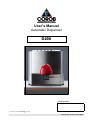
User’s Manual
Automatic Dispenser
D200
Serial Number
member of swisslog group
Preliminary version (July 2002)
© 2002 COROB S.p.A.
User’s Manual
Automatic Dispenser
D200
Preliminary version (July 2002)
© COPYRIGHT 2002, Corob ® S.p.A. All rights reserved.
No part of this manual may be reproduced in any form, or by any means, electronic or mechanical, including
photocopying and recording, without prior written permission of Corob ® S.p.A.
Information in this manual is subject to change without notice and does not represent a commitment on the
part of Corob ® S.p.A.
Unless otherwise indicated, all references to companies, names, data and addresses used in the screens
and/or examples are purely coincidental and serve only to clarify the use of the Corob product.
Corob ® S.p.A. shall not be liable for technical or editorial errors or omissions made herein; nor for incidental or
consequential damages resulting from the performance or use of this material.
If you require additional copies of this manual or further technical information about it, please write to:
COROB ® S.p.A.
Via Agricoltura 103 • 41038 San Felice s/P • Modena • Italy
Phone: + 39-0535-6633 • Fax: + 39-0535-663400
Printed in Italy.
0-2
D200
CONTENTS
CONTENTS
1
2
3
4
5
6
7
INTRODUCTION....................................................................................................................................... 1-1
1.1 Purpose and use of this manual ....................................................................................................... 1-1
1.2 Conventionally used graphics ........................................................................................................... 1-1
GENERAL INFORMATION ...................................................................................................................... 2-1
2.1 General safety warnings ................................................................................................................... 2-1
2.2 Residual risks .................................................................................................................................... 2-2
2.3 Position of labels ............................................................................................................................... 2-3
2.4 Identifying information and reference standards............................................................................... 2-3
2.5 Warranty............................................................................................................................................ 2-4
2.6 Definitions.......................................................................................................................................... 2-5
2.6.1 Personnel qualifications ........................................................................................................... 2-5
2.7 Fire extinguishing means to be used ................................................................................................ 2-5
2.8 Declaration of conformity .................................................................................................................. 2-6
FEATURES ............................................................................................................................................... 3-1
3.1 General description ........................................................................................................................... 3-1
3.2 Description of groups ........................................................................................................................ 3-2
3.2.1 Machine body........................................................................................................................... 3-2
3.2.2 Dispensing area and can handling system .............................................................................. 3-4
3.2.3 Humidifier cap .......................................................................................................................... 3-5
3.3 Technical specifications .................................................................................................................... 3-5
3.4 Performance and characteristics of the machine.............................................................................. 3-6
3.5 Cans to be handled ........................................................................................................................... 3-6
3.6 Minimum computer requirements...................................................................................................... 3-6
3.7 Intended and improper use ............................................................................................................... 3-7
SHIPPING, HANDLING AND UNPACKING ............................................................................................ 4-1
4.1 General warnings .............................................................................................................................. 4-1
4.2 Moving and handling the packed machine........................................................................................ 4-1
4.3 Environment conditions of the installation site .................................................................................. 4-1
4.4 Unpacking and placement................................................................................................................. 4-2
4.5 Moving and handling the unpacked machine.................................................................................... 4-2
4.6 Storage.............................................................................................................................................. 4-3
4.7 Dismantling and scrapping................................................................................................................ 4-3
INSTALLATION (by qualified personnel) .............................................................................................. 5-1
5.1 General warnings .............................................................................................................................. 5-1
5.2 Conditions for proper installation....................................................................................................... 5-1
5.3 Connecting the computer and installing the software ....................................................................... 5-1
5.4 Machine configuration through the management program ............................................................... 5-3
5.5 Filling the canisters and powering up the machine for the first time ................................................. 5-3
5.6 Moistening the cap sponge ............................................................................................................... 5-5
5.7 Calibration ......................................................................................................................................... 5-5
START-UP ................................................................................................................................................ 6-1
6.1 General warnings .............................................................................................................................. 6-1
6.2 Electrical connection and start-up ..................................................................................................... 6-1
6.3 Initialization........................................................................................................................................ 6-4
6.4 Shut-down ......................................................................................................................................... 6-5
USING THE DISPENSER ......................................................................................................................... 7-1
7.1 General warnings .............................................................................................................................. 7-1
7.1.1 Warnings on the use of colorants ............................................................................................ 7-1
7.2 Running ............................................................................................................................................. 7-1
0-3
CONTENTS
8
0-4
D200
7.3 Automatic timed stirring..................................................................................................................... 7-2
7.4 Refilling the canisters ........................................................................................................................ 7-3
7.5 Troubleshooting................................................................................................................................. 7-5
ORDINARY MAINTENANCE.................................................................................................................... 8-1
8.1 General warnings .............................................................................................................................. 8-1
8.1.1 Warnings on the use of colorants ............................................................................................ 8-1
8.2 Maintenance table ............................................................................................................................. 8-2
8.3 Cleaning ............................................................................................................................................ 8-2
8.3.1 External cleaning (dispenser) .................................................................................................. 8-2
8.3.2 Cleaning the nozzle center ...................................................................................................... 8-2
8.4 Moistening the humidifier cap sponge............................................................................................... 8-3
D200
1 - INTRODUCTION
1 INTRODUCTION
1.1 Purpose and use of this manual
This manual, inserted in the product packing, contains instructions on the installation, use, and routine
maintenance of the following equipment:
Automatic dispenser, model D200
This manual provides instructions on the routine maintenance needed to uphold the machine's performance
over time.
It is aimed at the machine operators and installers, who must have the necessary training and professional skill
to use similar automatic machines.
It also contains all information available at the time of publication regarding the machine and accessories;
since the latter are optional, they may not be installed on your machine. It thus also includes any variations or
changes that involve different operating procedures for either the installation technician or the operator.
Read this manual carefully before installing and using the machine.
It is organized into chapters, each of which refers to a specific topic.
The manual is to be considered an integral part of the machine, and must be stored until it is fully dismantled.
We recommend that you store it close to the machine so that it is easily accessible, in a place protected from
heat and damp.
Use the manual in such a way as to avoid damaging its contents; do not remove, tear, or rewrite any portion of
its contents.
Should it be lost or partially ruined, so that its contents can no longer be read in full, we recommend that you
request a new manual from the manufacturer.
Give this manual to any other user or subsequent owner of the machine.
Some of the illustrations in this manual were taken from prototypes; some details may differ on
machines in standard production.
1.2
Conventionally used graphics
The following graphics will be used in this manual to highlight special precautions or important suggestions for
safety purposes and for operating the machine properly.
WARNING / DANGER - Indicates a risk of personal injury.
CAUTION / IMPORTANT - Indicates a risk of damage to the machine that could interfere with its
operation.
This symbol indicates
measures to adopt.
important
instructions
This symbol indicates those operations
qualified or appropriately trained personnel.
referring
that
must
to
be
precautionary
carried
out
rules
and/or
solely
by
This symbol indicates situations and/or operations that involve the management application program
installed on the computer.
Boldface type is used to highlight notes or information of particular importance to a topic.
1-1
1 - INTRODUCTION
D200
BLANK PAGE
1-2
D200
2 - GENERAL INFORMATION
2 GENERAL INFORMATION
2.1
General safety warnings
This Corob dispenser has been designed and manufactured in observance of essential safety requirements;
the CE marking certifies its compliance.
All measures and precautions were taken during its design, manufacture, testing and installation to ensure the
highest possible level of safety considering rational use of the machine.
The warnings listed below are to be considered general in nature; specific safety instructions related to
the type of intervention to be carried out and the type of accessories installed on the machine are given in
detail in the specific paragraphs.
READ THE SAFETY WARNINGS CAREFULLY BEFORE USING THE MACHINE
WARNINGS
• Do not perform any type of work on the machine before you have read and understood the instructions in
this manual.
• Pay close attention to the warning signs on the machine.
• It is strictly forbidden to bypass or disable the protections and any safety devices present on the machine.
• The machine must not be used in areas at risk for explosion.
• The machine must be used only for its intended purpose.
• The machine is suitable for use with tinting products in general. Scrupulously follow the safety precautions
and the instructions for use given on the colorant package and on the safety data sheet supplied by the
manufacturer. When compulsory, use personal protection equipment for eyes and hands.
• The packing must be handled only by skilled personnel using appropriate handling equipment and according
to the instructions given in the corresponding chapter.
• During routine maintenance operations, scrupulously follow the safety instructions given in the
corresponding chapters before accessing the dangerous area.
• The panels must be kept closed at all times.
• Only qualified or appropriately trained personnel are authorized to access the electrical and mechanical
parts of the machine for maintenance and repairs.
• Unauthorized personnel are forbidden to remove the panels and access the electrical and mechanical parts
of the machine.
• Always unplug the power supply cable before carrying out any maintenance operations.
• During installation, maintenance and repairs to the machine, any operation that involves direct contact with
internal parts must be carried out with the machine off and with the power supply cable unplugged.
• Any intervention inside the machine when panels are open and when the machine is powered, must be
carried out by qualified or appropriately trained personnel and only when requested in the user’s manual.
• The machine must not be powered by a power source having specifications other than those listed on the
identification plate.
• Incorrect grounding may lead to the risk of electrical shock; always plug the machine into a socket that
ensures grounding according to current accident prevention regulations.
• The machine is isolated from the power supply line when the power cable is disconnected; it must therefore
be installed near an easily accessible mains socket outlet.
• Do not use extension cords to power the machine.
• Do not use multisockets to connect other equipment to the same socket that powers the machine.
• Periodically check the condition of the power supply cable; if it is damaged, replace it with a new cable
supplied by Corob.
• Do not remove or make illegible the signs indicating danger, warnings or instructions. Replace any sign
which has become illegible or is missing. These signs can be requested to the machine manufacturer.
2-1
2 - GENERAL INFORMATION
D200
• In the event of a sudden power outage, when power returns the machine will automatically be switched on
to allow the automatic processes to prevent products from drying out.
• In the event of a breakdown on any of the electronic control equipment, replace the damaged equipment
immediately; do not attempt to repair the breakdown (for qualified personnel only).
• The substances that may be used on the machine--such as colorants, paints, solvents, lubricants and
cleansers--may be hazardous to your health; handle, store and dispose of these substances in keeping with
current regulations and the instructions provided with the product.
2.2 Residual risks
Although all measures and precautions were taken during design, to ensure safe use of the machine, some
hazardous situations may occur for which complete elimination of the risk was not possible.
Risk
Preventive measure
Crushing during the cans loading and - Wear appropriate personal protective
unloading operations
equipment (shoes and gloves)
- Appropriate personnel training
Wounds and abrasions caused by sharp - Wear appropriate personal protective
edges and end parts of the cans to be equipment (cut-proof gloves)
handled
Dorsal/lumbar lesions caused by handling - Appropriate personnel training
of heavy loads
- Do not exceed the weight limits stated by
the current regulations in force (kg 20 for
women, kg 30 for men)
Contact or inhalation of colorants during - Wear appropriate personal protective
equipment (safety goggles, gloves and
the canister refilling operations
mask)
- Appropriate personnel training
Contact or inhalation of colorants during - Wear appropriate personal protective
the cleaning operations of the nozzle equipment (safety goggles, gloves and
mask)
center and moistening of the cap sponge
- Appropriate personnel training
2-2
Reference in
the manual
chapter 7
chapter 7
chapter 7
chapter 7
chapter 8
D200
2 - GENERAL INFORMATION
2.3 Position of labels
A warning label (code 7261007862) is applied on the rear aluminum profile of the machine (Figure 2-1).
The following general warnings are listed on the label:
1.
Read the manual carefully
Indicates the requirement to consult the instruction manual before carrying out any operation on the
machine.
2.
Access prohibited, do not open
Indicates that unauthorized personnel are forbidden to remove the panels and access the internal
components of the machine.
3.
Dangerous voltage
Indicates that there are live components inside the compartment. Risk of electrocution if you open the
compartment without first cutting off electrical power. Before removing the panels, always unplug the
power supply cable from the mains socket outlet.
1
Read the user’s manual before
operating the machine
Leggere attentamente il manuale
d’uso prima di utilizzare la
macchina
Leer atentamente el manual de
empleo antes de utilizar la
máquina
2
Unauthorized personnel are
forbidden to remove the panels and
access the internal components of
the machine
Al personale non addetto è vietato
l'accesso alle parti interne della
macchina protette da pannelli
Al personal no encargado está
prohibido el acceso a las partes
internas de la máquina protegidas
por paneles
3
Warning - Always unplug the power
supply cable from the socket before
removing panels
Attenzione - Scollegare il cavo di
alimentazione dalla presa di
corrente prima di rimuovere i
pannelli
Atención - Antes de quitar los
paneles, desconectar el cable de
alimentación de la toma de
corriente
Figure 2-1
2.4
Identifying information and reference standards
Corob S.p.A. designs, manufactures, and subjects its machines to tests to ensure compliance with safety and
electromagnetic compatibility regulations. Any changes not authorized by Corob S.p.A. may jeopardize this
compliance.
The equipment has been inspected and judged to conform to the Machinery Directive 98/37 of European
Commission, European Low Voltage Directive 73/23/EEC, as well as Directive 89/336/EEC on electromagnetic
compatibility and standard EN60204.1.
2-3
2 - GENERAL INFORMATION
D200
The machine has an identification plate on the rear aluminum profile, indicating (Figure 2-2):
1. manufacturer's name
2. patent number
3. CE marking
4. machine model
5. year of manufacture
6. serial number
7. electrical specifications
Do not remove or tamper with the identification plate in any way.
1
3
S. FELICE (MO) ITALY
2PATENT NO. 40094 A/84
MODEL
4
YEAR
5
S/N
6
7
Figure 2-2
2.5
Warranty
In order for the warranty to be valid, please complete the form included in the machine packing, and send it to
the address listed on the form itself.
Contact our authorized, qualified personnel only for all your service needs. Use only original Corob spare
parts for all maintenance and repairs.
WARNING - Altering or removing the guards and safety devices provided on the machine will not
only void the warranty immediately, but is also dangerous and illegal. The manufacturer may not be
held liable for personal injury or property damage caused by improper use of the equipment or
tampering with the guards and safety devices installed on the machine.
The following shall void the manufacturer's warranty:
• improper use of the machine
• failure to observe the instructions and maintenance rules set forth in the manual
• making or having changes and/or repairs made on the machine by personnel outside the authorized Corob
service organization
• making or having changes and/or repairs made using non-original spare parts
In the event of serious breakdowns, or if the user does not feel it appropriate to intervene directly,
contact your authorized Corob service center.
2-4
D200
2.6
2 - GENERAL INFORMATION
Definitions
2.6.1 Personnel qualifications
Indicates the minimum qualification level according to the table below.
OPERATOR
A person familiar with the use of colorants to produce paints or similar
products, assigned to operate and use the machine by its controls and to load
and unload production materials with all safety devices enabled.
He or she must work only in safety conditions.
Specialist prepared and trained in a technical field (mechanical and electrical)
MAINTENANCE TECHNICIAN and assigned to work on the machine to perform adjustments, repair
breakdowns or carry out maintenance.
2.7 Fire extinguishing means to be used
If the machine catches fire, you must use dry powder or carbon dioxide fire extinguishers. Never use water.
Carefully follow the instructions and warnings indicated by the manufacturer and listed on the extinguisher.
2-5
2 - GENERAL INFORMATION
2.8
D200
Declaration of conformity
D200
2-6
XXXXXX
D200
3 - FEATURES
3 FEATURES
3.1
General description
D200 is the latest-generation Corob dispenser based on a patented dispensing principle, made up of a volume
pump chamber powered appropriately to control the volume of the product to be dispensed.
The D200 automatic dispenser allows dispensing of colorants into containers pre-filled with base product, to
create paints, enamels and inks of the desired hue, chosen by means of the machine management program.
D200 is a sequential machine with a maximum of 16 dispensing circuits.
The dispenser is fully managed by a normal personal computer connected to the machine by a serial
connection. Corob supplies a wide range of software applications to manage all of the machine's functions.
The computer may be supplied by Corob upon request.
The dispenser essentially consists of (Figure 3-1):
− machine body (1)
− dispensing area and can handling system (2)
1
2
Figure 3-1
Tower version
Small and compact, D200 can be placed on a workbench (countertop version) or custom-made support
structure (floor-standing and tower versions) (Figure 3-2).
3-1
3 - FEATURES
D200
Countertop version
Floor-standing version
Tower version
Figure 3-2
3.2
Description of groups
This chapter gives a detailed description of the main machine groups.
3.2.1 Machine body
The circuits primarily consist of a dispensing group. The materials used ensure that the circuits are compatible
with both water-based and solvent-based products.
A dispensing group (Figure 3-3) may basically be divided into:
− Canister with intake filter and stirring system
− Pumping unit, with bellow pump, support mechanics, motor drive and electronic control devices
− Suction check valve and delivery check valve
3-2
D200
3 - FEATURES
1
8
7
2
9
3
6
4
5
Figure 3-3
Canisters (Figure 3-3)
The machine canisters (1) are suitable for containing the product to be dispensed.
The operator may access the canisters for refilling operations from the upper part of the machine; each
canister has its own lid (Figure 3-4).
Figure 3-4
To keep the product to be dispensed in the best possible condition of storage and homogeneity, each canister
is equipped with a stirrer with slanted blades (2), powered by a gear-motor (3) attached beneath the canister
itself.
At regular, programmable intervals, the management computer activates the stirrers for a programmable time,
one after another; the stirring time and interval between cycles may be set based on the physical nature of the
products in the canisters.
3-3
3 - FEATURES
D200
The rotation speed of the stirrer prevents the formation of air emulsions and other negative effects that could
interfere with the machine's performance.
During dispensing, if stirring is in progress it is interrupted to allow suitable working conditions; the stirring
cycle will start again at the end of dispensing.
Each canister has a filter that serves to trap any impurities that may be present in the product, protecting the
life-span, integrity and precision of the machine.
Pumping unit (Figure 3-3)
The pumping unit is made up of a bellow pump (4) of known volume, which expands and contracts based on
its shape and the action of a gear motor (5); during expansion, the volume chamber of the pump fills with
colorant drawn from the canister (intake stage), while during contraction the chamber empties, expelling
colorant through the dispensing pipe (8) towards the nozzles (9) (dispensing stage).
Dispensing from a circuit thus has an alternating pattern caused by the sequence of intake and dispensing
stages.
Each circuit has a motor drive. The control electronics ensure that the pump is working properly.
Suction check valve (6) and delivery check valve (7) (Figure 3-3)
Group of valves passively activated by the pump operation. The group determines the colorant input inside the
pump during expansion and colorant discharge from the pump towards the nozzle center during the
contraction stage of the pump itself.
Thus the machine contains no moving parts except for the bellow pumps while dispensing, or the stirrers in the
canisters while the colorant stirring cycle is in progress.
D200 is a sequential machine, this means that the circuits containing the colorants involved in the formula to
be dispensed are activated one at a time; the time needed for dispensing depends on the sum of the times for
the individual circuits.
3.2.2 Dispensing area and can handling system
The ends of all the dispensing circuits (8) converge and are fixed to the dispensing nozzle center (9) from
which the product flows out to fill the can (Figure 3-3).
The part including the nozzle center and can positioning area is known as the dispensing area (Figure 3-5).
The can handling system allows for the correct positioning of the can under the dispensing nozzles. For the
floor-standing and tower versions, the machine is equipped with a retractable shelf (1) with fixed height (Figure
3-5).
1
Figure 3-5
3-4
D200
3 - FEATURES
3.2.3 Humidifier cap
By their very nature, colorants tend to dry out; this tendency may be more or less strong depending on the type
of colorant and the environment conditions where the dispenser is installed, such as the temperature, relative
humidity, etc.
The machine is equipped with a humidifier cap to keep the dispensing nozzle center at a moisture level to
prevent the colorant from drying out; this device contains a moistened sponge which must be cleaned and
moistened periodically.
Sliding cap
The machine is equipped with a sliding cap (Figure 3-6). This is a simple cap, which opens thanks to the push
applied to the opening bar while the can is being positioned. The cap closes when the can is removed. The
system checks that the cap is properly opened and confirms the can presence to begin dispensing.
Figure 3-6
3.3
Technical specifications
ELECTRICAL SPECIFICATIONS
Power supply
Frequency
Fuses*
Maximum power absorbed*
Single-phase 100 - 240 V ~
50/60 Hz
T 6.3 A
90 W
NOISE LEVEL
Level of equivalent acoustic pressure
< 70 dB (A)
ENVIRONMENT WORKING CONDITIONS**
Temperature
Relative humidity
from 10°C to 40°C
from 5% to 85 % (without condensation)
VIBRATIONS
The machine does not transmit vibrations to the floor that may compromise the stability and precision of any
nearby equipment.
* Not including auxiliary devices powered by the machine.
** The climatic working conditions are strictly based on the type of colorants used (ask for information from the paint manufacturer). The
data shown are valid for the machine only.
3-5
3 - FEATURES
D200
OVERALL DIMENSIONS
Length
900 mm
Depth
790 mm
Height, countertop version
715 mm
Height, floor-standing / tower versions
1480 mm
WEIGHT*
Countertop version
Total machine
57 kg
Total packed machine
80 kg
Floor-standing version
Total machine
85 kg
Total packed machine
110 kg
Tower version
Total machine
87 kg
Total packed machine
112 kg
* Figures are purely indicative, and depend on the exact configuration of the machine (number of circuits, type of support for the computer
and/or monitor, etc.). The data refer to the machine with the canisters empty.
3.4
Performance and characteristics of the machine
Dispensing system
volumetric - sequential
Dispensing center
internal
Number of circuits
up to 16
Canister capacity
2.5 liters
Type of canisters
all-purpose (POM acetalic resin)
Type of valves
check valves
Circuit flow rate
Minimum dispensed quantity
0.2 l/min
1/384 fl oz (0.077 ml)
Standard accuracy
Nozzle center flow diameter*
± 1%
31 mm
* If the cans are pre-punched, the hole diameter must be as follows: flow diameter + 15 mm.
3.5
Cans to be handled
The ergonomics of the D200 dispenser and the presence of its retractable shelf with fixed height make it
suitable for handling 1-Gallon cans, and occasionally 5-Gallon cans.
3.6
Minimum computer requirements
The minimum computer requirements needed to manage the machine depend entirely on the application
software used.
See the program manual for a list of its minimum requirements.
In any case, the computer must have at least two serial ports, needed to communicate with the dispenser
and connect the calibration scale.
3-6
D200
3.7
3 - FEATURES
Intended and improper use
The automatic dispenser is a device to automatically dispense (or distribute) fluid colorant products into
containers (metal or plastic canisters, cans or bins) of the size indicated in chapter 3.5, pre-filled with base, to
produce finished products such as paints, dyes, enamels, and inks of the desired hue.
The machine must be used only within the limitations set forth by the technical specifications and
according to the procedures described in this manual.
Any use other than that stated, which cannot be implied or deduced from this manual, is to be
considered prohibited.
3-7
3 - FEATURES
D200
BLANK PAGE
3-8
D200
4 - SHIPPING, HANDLING AND UNPACKING
4 SHIPPING, HANDLING AND UNPACKING
4.1
General warnings
To avoid personal injuries and property damage, use the utmost care and caution when handling
the machine, and carefully follow the instructions given in this chapter.
The packing must be handled only by skilled personnel using appropriate handling equipment. Never
move the packing by hand or with inappropriate means, to avoid personal injury or breaking the
machine.
Make sure no one is in the vicinity during those unpacking operations that involve cutting or
removing binding systems using hazardous instruments.
4.2
Moving and handling the packed machine
The machine is carefully packed and prepared for shipping, firmly fastened to a sturdy wooden base (pallet),
covered externally with a wooden crate or cardboard box, and wrapped with bubble plastic, cellophane, special
corrosion-proof paper, etc., depending on the type and duration of shipping planned for delivery.
Use appropriate lifting equipment (lift truck with flat forks) to lift, handle and/or move the packed machine, as
follows:
–
Position and space the lift forks to insert them into the pallet;
–
insert the forks into the slots provided on the pallet;
–
lift the packing;
–
handle and move as needed, and carefully position it near the installation site.
4.3
Environment conditions of the installation site
Environment requirements for the site where the machine is to be installed.
• Clean and dust-free
• A level, stable surface
• Fitted with a grounded power supply socket
• Equipped with sufficient lighting. The machine workplace must be equipped with devices that allow
adequate artificial light, to protect the operator's health and safety. The room lighting must therefore ensure
good visibility from every point of the machine.
The environment working conditions of the machine must meet the following requirements:
• Temperature between 10°C (50°F) and 40°C (104°F)
• Relative humidity: from 5% to 85 % (without condensation)
The climatic working conditions may vary according to the type of colorants used. The proper values are
provided by the paint manufacturer or indicated on the colorant package and safety data sheet. The climatic
conditions listed above are valid for the machine only.
Environment conditions outside the values indicate may cause serious damage to the machine,
especially the electronic equipment.
The area called the operator area (border area around the machine) must remain as dry as possible
and free of obstacles.
4-1
4 - SHIPPING, HANDLING AND UNPACKING
4.4
D200
Unpacking and placement
Make sure the packing has not suffered any damage or tampering during shipping; if so, contact the
authorized technical service or your dealer.
We recommend that you store the packing material for future use, or dispose of it according to current
regulations. In any case, we recommend that you keep it for the entire duration of the machine warranty.
To unpack the machine, follow the instructions below:
1. Cut the plastic straps wrapped around the packing (cardboard box only).
2. Remove the covering from the pallet, also removing the corresponding fasteners.
3. Remove the bubble plastic and/or cellophane wrapped around the machine.
Make sure the machine has not been damaged during shipping; if so, do not attempt to start it. Contact
the authorized technical service or dealer immediately.
Inside the packing you will find the material supplied:
• power supply cable
• computer/machine communication cable
• computer power cables
• a kit of spare fuses
• user's manual
• CE declaration of conformity and installation and warranty start form
Depending on the options specified on the purchase order, you may also find:
• management program with corresponding user's manual and protection key
Make sure that all of the above items are included in the packing; if not, contact the manufacturer.
To remove the machine from the pallet, lower it to the ground and place it correctly on the installation site,
follow the procedure below carefully:
1. Remove the systems that fasten the machine firmly to the pallet.
At least 3 people must work together to remove the machine from the pallet.
You must wear cut-proof safety gloves when lifting the machine.
2.
3.
4.5
With one person at the right side and another person on the left side, lift the machine straight up until the
pallet is free and can be removed by the third person.
Once the pallet has been removed, carefully place the machine in its working position. The machine
support surface must be stable and level and capable of withstanding the necessary weight (see technical
specifications).
Moving and handling the unpacked machine
Should it become necessary for any reason to move the machine from its original site proceed as follows:
1. Use the main switch to shut off the machine, and unplug the power supply cable from the mains socket
outlet (chapter 6.4).
At least 2 people must work together to move the machine.
You must wear cut-proof safety gloves when lifting the machine.
2. For short moves, push the machine into its new working position; if the machine must be lifted, at least 2
people are needed.
3. Connect the power supply cable and switch on the machine using the main switch (chapter 6.2).
We recommend reusing the original packing any time the dispenser must be moved or shipped.
4-2
D200
4.6
4 - SHIPPING, HANDLING AND UNPACKING
Storage
If stored, the machine must be kept in a protected, dry environment, not subjected to harsh weather, to avoid
damaging the electrical components.
It is forbidden to stack items on the packing.
4.7
Dismantling and scrapping
When the machine is no longer to be used (broken or at the end of its life-span) it must be demolished.
The machine must be scrapped using the appropriate equipment based on the type of component in
question (motor, pump, etc.). The machine components must be broken down into small parts so that they
cannot be reused.
When scrapping, the machine parts must be disposed of according to the type of material they are made of;
the machine is primarily made up of the following materials:
• ferrous metal material
• non-ferrous metal material
• electrical components, wiring and electronic boards
• plastic parts
Hire specialized, authorized firms for this purpose, and always follow local regulations.
If any colorants have been used that require special disposal procedures, follow local regulations for the
colorants remaining in the canisters and for those machine components most soiled with colorant.
4-3
4 - SHIPPING, HANDLING AND UNPACKING
D200
BLANK PAGE
4-4
D200
5 - INSTALLATION
5 INSTALLATION (by qualified personnel)
5.1
General warnings
Only qualified or appropriately trained personnel are authorized to install the machine.
Before installing the machine, read the instructions in this chapter carefully to ensure the
safety of the personnel involved and avoid damaging the machine.
Once the machine has been unpacked and placed in its operating site, it must be installed.
5.2
Conditions for proper installation
You must observe the environment conditions described in chapter 4.3.
You must also prepare an electrical power line in accordance with the voltage and frequency required by the
machine, listed on the identification plate (chapter 2.4).
The line must be protected from overloads, short-circuits and direct contacts according to current regulations.
Check the grounding of the power supply system as required by local regulations before
installing or powering the machine.
Installing a Corob dispenser involves:
• connecting the computer to the machine and installing the application software
• configuring the machine through the management program
• first canister filling and priming the pumps
• moistening the sponge in the humidifier cap
5.3
2
Connecting the computer and installing the software
We recommend that this connection be carried out by personnel skilled with computers.
To connect your computer to the machine, use the computer/machine serial communication cable provided
in the packing. For any information on the computer, refer to the corresponding user’s manual.
The machine has auxiliary sockets with the exclusive purpose to power the computer and all peripheral
equipment such as label printer or calibration scale (chapter 6.2). The auxiliary sockets are located inside the
machine and can be accessed by removing the left side panel.
The auxiliary sockets are powered when the machine main switch is switched on (chapter 6.2).
To power up the computer use the power cords provided in the packing (chapter 4.4).
1.
2.
3.
Position the computer.
If the computer is complete with monitor and keyboard, connect as needed.
To connect the computer to the machine, it is first necessary to remove the left side panel so as to gain
access to the auxiliary sockets located inside the machine:
– unscrew the screws and remove the upper covers of the aluminum profiles on the left and back side
(Figure 5-1).
– unscrew the screws that fix the left side panel to the aluminum profiles.
– wear cut-proof gloves in order to protect your hands, and slide up the panel as shown in Figure
5-2 and Figure 5-3.
5-1
5 - INSTALLATION
D200
Figure 5-1
Figure 5-2
Figure 5-3
4.
5.
5-2
Connect the computer and monitor power supply cords (1) to the auxiliary sockets (2) (Figure 5-5), by
passing them through the opening at the base of the frame (Figure 5-4). Do not use power cords that are
not in good condition or are unsuitable.
Connect the computer to the machine using the communication cable as follows:
– Connect the 9-pin female connector of the serial interface cable to the serial port of the computer
(preferably serial port COM1); if the serial port connector of your computer has 25 pins, use a 9/25-pin
adapter.
– Place the communication cable inside the machine, by passing it through the opening at the base of
the frame (Figure 5-4).
– Insert the communication cable connector (3) (RJ11 male) into the connector (4) (RJ11 female) (Figure
5-5).
D200
5 - INSTALLATION
1
2
4
3
Figure 5-4
Figure 5-5
6.
5.4
Load the management application program onto your computer.
– Press the computer and monitor start switches to turn them in ON position (I).
– Power up and start the machine as described in chapter 6.2.
– When the computer is booted up, install the application software (see the program user's manual).
Machine configuration through the management program
Use the ColorTECH configuration and calibration program at this point to configure the machine (see
the ColorTECH program user's manual).
If you are using a ColorTECH version prior to 4.6 or, in any case, unsuitable for a Banco/D200 dispenser, it is
necessary to modify the preset value of the Change between the two dispensing speeds: set the Change value
to 1 cc instead of 6 cc. Proceed then with the association between colorants and canisters.
5.5
Filling the canisters and powering up the machine for the first time
During installation, it is necessary to fill the machine canisters with the colorants of the system used, by
following the procedure indicated below. Then, it is essential to proceed with machine calibration (chapter 5.7).
Use the ColorTECH configuration and calibration program to correctly perform first canister filling and
prime the pumps. We recommend that you use ColorTECH version 4.5 and following. For any information
about program installation, startup and use, refer to the relevant user’s manual.
To avoid emulsifying air into the product, never use automatic shakers to shake the colorant to
be poured into the canisters. Shake manually.
1.
2.
After turning the machine ON (chapter 6.2), start the ColorTECH calibration program.
Load a can on the machine, by placing it on the shelf or on the workbench (chapter 7.2).
5-3
5 - INSTALLATION
3.
4.
D200
From ColorTECH, send the Bellows up command to compress all of the bellow pumps of the machine.
Fill the canisters with colorant as follows (Figure 5-6/Figure 5-7):
– shut off the machine (chapter 6.4) to prevent the stirring process from being activated during canister
refilling
– remove the lid of the canister to be filled
– remove the bottle draining system (1) so as to access the clip that fixes the stirrer structure to the
stirrer rod; press the wings of the clip (2) and pull the stirrer structure (3) upward, to remove both the
structure itself and the filter (4)
– fill the bottom of the canister with colorant
– reassemble the stirrer structure and the filter, and fit the bottle draining system back in its place
– finish refilling the canister, by pouring at least 1 liter of colorant
Carefully follow the warnings in chapter 7.4 regarding filling the canisters.
– close the canister with its lid and repeat the above steps for all the canister of the machine
– restart the machine (chapter 6.2)
For further information on the procedure of canister filling, refer to chapter 7.4.
2
1
3
4
Figure 5-6
Figure 5-7
5.
From ColorTECH, send the command to expand all the bellow pumps of the machine: use the Reset
command.
6. Make sure that a can is placed on the shelf or on the workbench. The can must have an adequate
capacity, at least enough to contain the amount of colorant about to be dispensed (at least 250 ml).
7. From ColorTECH, send the Bellows up command to compress all the bellow pumps of the machine and
thus dispense.
8. From ColorTECH, send the command to expand all the bellow pumps of the machine: use the Reset
command if the machine features a firmware version 30.11.09, or use the Bellows down command if the
machine features a firmware version 30.11.10 and following.
9. Repeat steps from 6 to 7 for at least 3 times.
10. From ColorTECH, send the Test command to check the efficiency of all machine circuits.
The firmware version is indicated on the CB Master board, located on the board panel at the front side of
the machine.
To access the CB Master board, it is necessary to remove the front panel of the machine; this
operation must be carried out with the machine off and with the power supply cable unplugged.
Use the ColorTECH configuration and calibration program at this point to save the amount of colorant
added to the canisters during installation (see the ColorTECH program user's manual).
5-4
D200
5 - INSTALLATION
While the machine is being used, the management program warns the operator when the amount of
colorant in the canisters reaches the reserve level and is insufficient for dispensing a formula; in this case you
must add colorant to those canisters that have reached reserve level (chapter 7.4).
5.6
Moistening the cap sponge
Installation now requires that you moisten the sponge in the humidifier cap, which serves to keep the
dispensing nozzle center at a moisture level to prevent the colorant from drying out.
The procedure for moistening the sponge is described in the chapter on ordinary maintenance of the humidifier
cap, specifically in chapter 8.4.
5.7
Calibration
Since the characteristics of the colorant in relation to the circuit containing it greatly affect the machine's
precision, it is essential to CALIBRATE all of the dispensing circuits. The ColorTECH program allows you to
automatically calibrate the machine starting from theoretical calibration parameters.
After filling the canisters, we recommend leaving the colorant to degas from air for 8-12 hours before
calibrating; during this time it is advisable to increase the automatic stirring frequency so that the colorants are
in ideal condition during calibration.
To calibrate the machine, you must use a precision scale since the actual calibration parameters are
calculated based on the weight of the amounts dispensed during calibration.
You may use an electronic scale that can interface with the computer, among those managed by the
ColorTECH calibration program. See the scale manual for instructions on interfacing the scale with the
machine management computer. In any case, it is advisable to use the COM2 serial port on the computer.
The instructions for automatically calibrating the dispensing circuits of the machine are described in detail in
the ColorTECH program user's manual.
If you are using a ColorTECH version prior to 4.6 or, in any case, unsuitable for a Banco/D200 dispenser, it is
necessary to modify the preset values of calibration as follows:
• Set graphic calibration type
• Modify the preset value of the Theoretical MPX, which the program suggests when calibrating a circuit for
the first time: change this value to 800 instead of 476,19.
• Modify the calibration steps and the number of tests for both the low and the high speed, as follows:
Speed 150 - from 0 cc to 1 cc
Speed 999 - from 1 cc on
1000-800-600-500-400
4 calibration tests
40000-8000-5000-3000-2000-1000-800 2 calibration tests
When calibration is over, send from ColorTECH the command Check calibration to verify the calibration just
carried out.
5-5
5 - INSTALLATION
D200
BLANK PAGE
5-6
D200
6 - START-UP
6 START-UP
6.1
General warnings
The machine is manufactured according to various electrical power standards (see technical specifications).
The type of power supply is indicated on the identification plate.
THIS EQUIPMENT MUST BE GROUNDED.
Check the grounding of the power supply system before connecting the machine.
The computer and any other devices connected to the machine via a serial line or connected to
the computer itself must be powered via the auxiliary sockets.
Do not attempt to power the machine from a source having specifications other than those listed on the
identification plate.
The machine is isolated from the power supply line when the power cable is disconnected; it must
therefore be installed near an easily accessible mains socket outlet.
Do not use extension cords to power the machine. Do not use multisockets to connect other
equipment to the same socket that powers the machine.
Do not use multisockets to connect other equipment to the machine auxiliary sockets.
The machine is equipped with a power supply cable having the following specifications: length 3 m, crosssection 3 x 1 mm².
Important - The power supply cable conductors are color-coded as follows:
GREEN/YELLOW = EARTH
BLUE = NEUTRAL
6.2
BROWN = LINE
Electrical connection and start-up
The following are present inside the machine (Figure 6-1):
3
2
1
4
Figure 6-1
6-1
6 - START-UP
Main plug (1)
Fuse compartment (2)
Auxiliary sockets (3)
RJ11 female connector (4)
D200
Main power supply to the machine.
The two fuses protect the line and neutral in the electrical socket; the
value is shown in the technical specifications table.
Power supply to the computer and other equipment (calibration scale or
label printer).
Serial interface connection to the machine management computer.
The following device is present on the right side of the machine, under the basement of the machine body
(Figure 6-2):
Figure 6-2
Machine main switch
Green led switch. In ON position (I), the machine is powered. In OFF
position (O), the power is cut off to the machine.
To power up and start the machine, proceed as follows:
1. Make sure that the machine main switch is in the OFF position (O) (Figure 6-2).
2. To power up the machine, it is first necessary to remove the left side panel so as to gain access to the
main plug located inside the machine:
– unscrew the screws and remove the upper covers of the aluminum profiles on the left and back side
(Figure 6-3).
– unscrew the screws that fix the left side panel to the aluminum profiles.
– wear cut-proof gloves in order to protect your hands, and slide up the panel as shown in Figure
6-4 and Figure 6-5.
6-2
D200
6 - START-UP
Figure 6-3
Figure 6-4
Figure 6-5
3.
Insert the power supply cable socket (1) into the main machine plug (2) (Figure 6-6), let the cable pass
through the opening at the base of the frame (Figure 6-7) and insert the other end to the mains socket
outlet.
1
2
Figure 6-7
Figure 6-6
6-3
6 - START-UP
4.
5.
D200
Wear cut-proof gloves in order to protect your hands, lower the left side panel, fix it with the screws
previously removed and fit back the upper covers of the aluminum profiles on the left and back side.
Set the machine main switch to the ON position (I) (Figure 6-8); the computer, monitor and all instruments
powered through the auxiliary sockets will turn on.
Figure 6-8
Once the main switch has been turned on, the machine prepares for use by automatically carrying out a
system check.
When it is turned on, the computer automatically loads the installed application program. When the
program is launched it offers the operator a series of procedure requests, including initialization (see the user's
manual for the application software).
6.3
Initialization
INITIALIZATION is a preparatory phase that must be carried out when the machine is turned on, and
when the configuration parameters are set again.
If the computer only is turned off and back on again, initialization is not strictly necessary, even if
required by the program; it is solely at the discretion of the operator.
During initialization, the application program sends the machine the times and parameters that control the
timed processes and that govern operation of the machine.
The start-up phase of the application program also involves carrying out dispensing test or nozzle purging, at
the operator's discretion (based on the configuration of the application software).
Once the start-up phase is complete, the application program is set to a logical, pre-defined state awaiting
commands from the keyboard.
The timed process of Colorant stirring begins after a few seconds of machine inactivity (chapter 7.3).
6-4
D200
6.4
6 - START-UP
Shut-down
WE RECOMMEND THAT YOU NEVER SHUT DOWN THE MACHINE, even when closed for business,
because the automatic, timed functions help keep the colorant preserved and homogeneous.
The absorbed power of the machine is very low when it is switched on but inactive, or during a stirring
cycle.
Should it be essential to shut down the machine, avoid keeping it off for extended periods of time. When
the machine is not being used, shut off only the computer.
To shut off the machine, proceed as follows:
1. After carrying out the computer shut-down procedure, set the machine main switch to the OFF position
(O).
2. Unplug the power supply cable from the mains socket outlet.
6-5
6 - START-UP
D200
BLANK PAGE
6-6
D200
7 - USING THE DISPENSER
7 USING THE DISPENSER
7.1
General warnings
The machine must be used by a single operator.
It is strictly forbidden to bypass or disable the safety devices and protections.
Keep hands away from the dispensing area at all times while the machine is operating.
The panels must be kept closed at all times.
The substances that may be used on the machine--such as colorants, paints, solvents, lubricants and
cleansers--may be hazardous to your health; handle, store and dispose of these substances in keeping
with current regulations and the instructions provided with the product.
7.1.1 Warnings on the use of colorants
Before using any colorant, carefully read the SAFETY DATA SHEET that the dealer or
manufacturer of the product is required to provide, and observe all of the safety instructions provided.
Below are some of the most common warnings and safety precautions provided by colorant manufacturers.
Harmful if swallowed.
Avoid eye and skin contact. In case of eye and skin contact, rinse with plenty of water.
Keep out of the reach of children.
When compulsory, wear protecting equipment for eyes and hands.
In case of accidental product leaks or spills, thoroughly ventilate the area and clean immediately with
water.
Do not dispose of colorant in the sewage system. Follow local regulations when disposing of waste.
7.2
Running
The operator is guided in running the machine by the Corob management application program, which displays
the instructions to be carried out and the actions performed by the machine.
After selecting the appropriate options from the application program (selection of the product, formula and
cansize) proceed as described below.
1.
Load the can required to obtain the desired product, using the positioning system provided on the
machine.
Pull out the shelf (if present) then place the can to push the opening bar inward and thus cause the cap to
open (Figure 7-1).
2. Automatic dispensing.
Dispense the formula by entering the command in the application program; the machine will begin to dispense
the colorants included in the formula in the set amounts.
The circuits containing the colorants involved in the formula to be dispensed are activated one at a time; the
time needed for dispensing depends on the sum of the times for the individual circuits.
7-1
7 - USING THE DISPENSER
D200
Figure 7-1
7.3 Automatic timed stirring
Colorant stirring is a timed process, activated automatically to properly store the product in the canisters and
keep it in ideal, homogeneous conditions for dispensing.
The times regulating this process may be set via the configuration program (see the ColorTECH
program user's manual) depending on the physical nature of the colorants used on the machine.
The stirring process consists of activating the stirrers located inside the canisters (Figure 7-3), one after
another, beginning with the one inside the first canister; the stirring process (cycle) ends when the last canister
has been stirred.
The movement of the stirrers keeps the colorant in the canisters homogeneous.
Stirring also serves to prevent the precipitation of pigments, flocculation and sedimentation of the colorants in
the canisters.
The rotation speed of the stirrers prevents the formation of air emulsions and other negative effects that could
interfere with the machine's performance.
Keep the canisters closed with their corresponding lids, and do not insert hands in the canister
even when no colorant is present.
Stirring may also be activated directly by the operator whenever necessary.
The stirring times set via the application program are sent to the machine during initialization; the timed
process is active even if the machine is turned on without the computer. The machine uses the following preset
times:
• the stirring time is 30 seconds
• the interval between cycles is 30 minutes
The stirring time is the duration of stirring in a single canister; the total duration of the process will be the
stirring time multiplied by the number of canisters.
If the machine must be used while the timed process is taking place, it may be suspended simply by
ordering dispensing or another process via the management application program; the stirring process will start
again after a few seconds from the machine stop.
7-2
D200
7 - USING THE DISPENSER
7.4 Refilling the canisters
Before using any colorant, carefully read the SAFETY DATA SHEET that the dealer or
manufacturer of the product is required to provide, and observe all of the safety instructions provided.
When compulsory, use personal protection equipment for eyes and hands.
Corob management programs control the level of colorant in the machine canisters to ensure the hue of
the paint being produced. By knowing the initial level for each colorant, the program can decrease the level
based on the amount dispensed. Insufficient colorant in the canisters lowers the machine's performance and
may lead to mistints.
It is essential to avoid letting the level of colorant fall too low or, worse yet, allowing the machine
canisters to empty completely.
Using the Corob management programs, a reserve level is set for each canister in proportion to its
capacity, to prevent it from emptying; when the colorant in a canister reaches the reserve level, the program
prevents all formulas involving the color in reserve from being dispensed.
Scrupulously follow the safety precautions and the instructions for use given on the colorant
package; when compulsory, use personal protection equipment for eyes and hands.
If "SOLVENT FREE" colorants are used, or those that dry out quickly, we recommend that you keep the
canisters full at all times by topping up frequently.
To add colorant to a canister, proceed as follows:
(Figure 7-2/Figure 7-3)
1. Shut off the machine to prevent the stirring cycles from being automatically activated while you are topping
up (chapter 6.4).
2. Remove the lid of the canister to be filled.
3. Make sure that the bottle draining system (1) is present and correctly positioned, then add the desired
amount of colorant to the canister, by pouring it directly on the bottle drainer, so as to avoid spattering or
creating air emulsions in the colorant.
To avoid colorant spills from the shaft of the stirring system, it is essential that you DO NOT
remove the bottle drainer while topping up. The colorant level MUST NOT exceed the maximum level at
no less than 5 cm (2 in. approx.) from the upper edge of the canister. Colorant spills will cause the
pumping unit to be blocked.
4. Close the canister with its corresponding lid.
5. Repeat the above steps to fill other canisters.
6. Restart the machine.
7-3
7 - USING THE DISPENSER
Max 2.5 l
2.64 qt
2.1 l
2.22 qt
1.3 l
1.37 qt
D200
REFILLING
RABBOCCO
REMPLISSAGE
NACHFÜLLUNG
1
LLENADO
0.6 l
0.63 qt
ENCHIMENTO
2
HOW - COME - COMMENT - WIE - CÓMO - COMO
YES
NO
TO - FIN DOVE - JUSQU'À - BIS ZU - HASTA - ATÉ
YES
Figure 7-3
NO
2 in. approx.
5 cm circa
5 cm environ
5 cm ungefähr
5 cm aprox
5 cm aprox
Figure 7-2
If colorant bottles are used it is advisable to place them onto the suitable bottle draining system (1)
located on the stirring shaft (2) (Figure 7-3); this will aid colorant slow pouring along the canister shaft thus
preventing air emulsion.
Each time colorant is added to the canisters, it is essential to update the amount of colorant associated
with the topped up canisters, entering the new colorant level in the program (see the application program
user's manual).
Update the levels IMMEDIATELY AFTER topping up the colorant in the machine canisters, so that you
do not forget to do so later.
Changing the levels so that they do not match the actual amount of colorant added to the canisters may
compromise the accuracy of the hue produced or, worse yet, cause malfunctions in the machine due to
emptying the canisters and circuits.
After topping up the colorant, it is advisable to carry out the stirring process using the functions provided in the
management application program, to eliminate any air that may be emulsified and incorporated into the
colorant.
7-4
D200
7.5
7 - USING THE DISPENSER
Troubleshooting
Problem
Cause
Power supply is missing.
Mains switch in OFF position (O).
The machine does
not turn on.
One or more fuses may be blown up.
Electrical connections are defective.
The power
overcurrent.
supply
unit
Machine disconnected
computer.
is
from
in
the
Serial cable damaged.
Computer
serial
port
configured or defective.
The management
application program
shows an error in
the communication
protocol.
wrongly
Serial connection defective.
Machine is OFF.
The valve of the pumping unit does
not work correctly.
Solution
Check the connections inside the machine
(chapter 6.2).
Set the main switch to the ON position (I)
(chapter 6.2).
Replace any blown fuse in the fuse
compartment, located inside the machine
(chapter 6.2).
Contact the authorized technical service.
Wait a few minutes and try to restart the
machine. If the problem persists, contact the
authorized technical service.
Check the connections inside the machine
(chapter 6.2).
Replace the communication cable using Corob
original spare parts.
Use the ColorTECH program to make sure you
have correctly configured the serial port used to
communicate with the machine.
Repair the computer serial port.
Contact the authorized technical service.
Turn the machine on and restart the
management application program (chapter 6.2).
From the management application program
dispense approx. 100 cc of colorant (chapter
7.2) from the pumping unit involved. If the
problem involves many circuits, repeat the
above operation for one circuit at a time, so as
to recycle the colorant dispensed.
If the problem persists, contact the authorized
technical service.
7-5
7 - USING THE DISPENSER
D200
BLANK PAGE
7-6
D200
8 - ORDINARY MAINTENANCE
8 ORDINARY MAINTENANCE
8.1
General warnings
Performing ordinary maintenance regularly ensures safe, reliable machine operation.
Before carrying out any ordinary maintenance operations, you must turn off the machine and
unplug the power supply cable from the mains socket outlet.
The frequencies indicated are approximate, since they depend on the type of colorants and environment
conditions.
Make sure to use products compatible with the type of colorants in the machine when: cleaning the
nozzle center - moistening the humidifier cap sponge.
Type of colorant:
Solvent-based colorants
Water-based colorants
Mixed systems
Use:
slow-evaporating solvent, compatible with the colorants used
water
the choice depends on the type of vehicles used to produce the colorants; this
choice may be made directly by the paint manufacturer development laboratory
or, alternatively, by the Corob laboratory after examining the formulas and a few
samples of the products used.
During the maintenance operations described below, follow the safety instructions given; refer to chapter 2.6
for further clarification of the definitions.
Machine status:
Number of operators:
Qualification:
shut off and unplugged from the power source
1
operator
8.1.1 Warnings on the use of colorants
During machine maintenance operations there is a high risk of contact with the coloring
products; carefully read the SAFETY DATA SHEET that the dealer or manufacturer of the product is
required to provide, and observe all of the safety instructions provided.
Below are some of the most common warnings and safety precautions provided by colorant manufacturers.
Harmful if swallowed.
Avoid eye and skin contact. In case of eye and skin contact, rinse with plenty of water.
Keep out of the reach of children.
When compulsory, wear protecting equipment for eyes and hands.
In case of accidental product leaks or spills, thoroughly ventilate the area and clean immediately with
water.
Do not dispose of colorant in the sewage system. Follow local regulations when disposing of waste.
8-1
8 - ORDINARY MAINTENANCE
D200
8.2 Maintenance table
OPERATIONS
EVERY 20 hours *
EVERY beginning of shift *
* The value is purely indicative.
*
*
Clean the dispenser externally (chapter 8.3.1)
Accurately clean the dispensing nozzles (chapter 8.3.2)
*
8.3
Moisten the sponge of the humidifier cap (chapter 8.4)
Cleaning
8.3.1 External cleaning (dispenser)
The machine may get dirty accidentally (paint spills) or due to dust build-up over time. In the first instance, the
machine must be cleaned immediately; periodic cleaning will suffice for the latter.
Every beginning of shift (daily) we recommend a general cleaning of coverings, panels and control devices
of the machine, to remove dirt, dust and any colorant stains, using a soft and dry cloth, or slightly moistened
with a mild cleansing solution.
Never use a solvent-based cleaning product or abrasive powder, since they might ruin surfaces.
See the computer manual for instructions on cleaning the computer.
8.3.2 Cleaning the nozzle center
For precise dispensing, it is essential to keep the dispensing nozzles in the best possible condition.
Every beginning of shift (daily) check the condition of the nozzle center.
If necessary, clean the nozzles carefully with a damp cloth.
The type of cleaning product to use depends on the type of colorants used on the machine; follow the table
given in chapter 8.1 for the type of solution to be used.
Remove any dried colorant residue with a sharp tool.
Perform this operation delicately to avoid damaging the ends of the dispensing circuits that make up the
nozzle center.
–
–
–
–
–
8-2
shut off the machine and unplug the power supply cable
open the sliding cap by pushing the opening bar inward with your hand
perform maintenance on the nozzles
bring back the sliding cap in its closed position
connect the machine to the power mains and switch it on as described in chapter 6.2.
D200
8 - ORDINARY MAINTENANCE
Figure 8-1
8.4
Moistening the humidifier cap sponge
In addition to keeping the nozzle center clean at all times, in order to obtain precise dispensing from the
machine it is essential that the nozzle center be kept at a moisture level to prevent the colorant from drying out.
For this purpose, the humidifier cap installed on the machine contains a sponge that must be kept moist at all
times.
Every 20 hours (approximately every two days) moisten the sponge.
The type of product to use depends on the type of colorants used on the machine; follow the table given in
chapter 8.1 for the type of solution to be used.
Visually check the status of the sponge and moisten as needed (do not saturate).
If it is very dirty, remove the sponge from the cap and wash it thoroughly.
Replace it if it is severely damaged.
–
–
–
–
–
–
–
–
–
shut off the machine and unplug the power supply cable
open the sliding cap by pushing the opening bar inward with your hand
remove the sponge holding lid
release the lever of the sliding cap to bring it back in its closed position
perform maintenance on the sponge
push the opening bar to cause the cap to open
fit back the sponge holding lid
bring back the sliding cap in its closed position
connect the machine to the power mains and switch it on as described in chapter 6.2.
8-3
8 - ORDINARY MAINTENANCE
D200
Figure 8-3
Figure 8-2
Figure 8-4
8-4