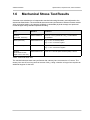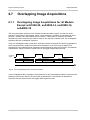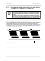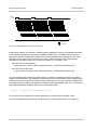
1
AW00123404000
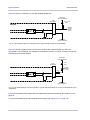
Physical Interface
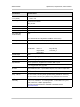
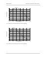
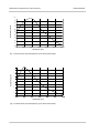
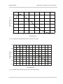
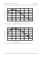
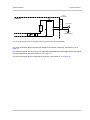
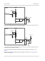
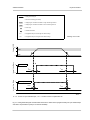
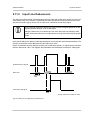
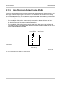
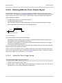
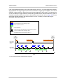
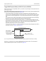
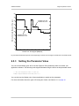
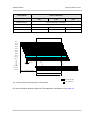
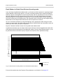
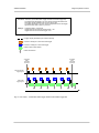
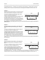
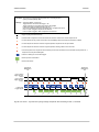
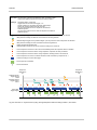
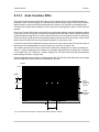
= Analog external signal
= Internal line status (logical levels)
HIGH
= Voltage region considered to indicate a "high" internal logical level
LOW
= Voltage region considered to indicate a "low" internal logical level
= "Fast" edge
Voltage [VDC]
= Transition threshold
Internal Line Status
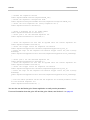
= Propagation delay for the low-high line status change
tPHL
= Propagation delay for the high-low line status change
Drawing not to scale
#
HIGH
0
Internal Line Status
tPLH
1
LOW
*
Opto-isolated IN
tPLH
tPHL
0
1
*
Direct-coupled GPIO IN
tPLH
tPHL
0
Time
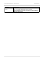
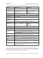
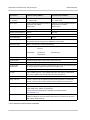
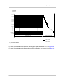
#: 3.3 - 24 VDC for opto-isolated input, >2.0 - 5.0 VDC for direct-coupled GPIO IN
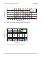
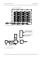
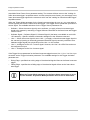
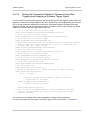
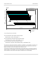
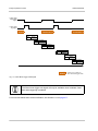
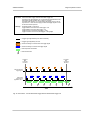
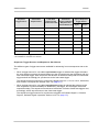
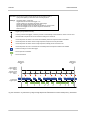
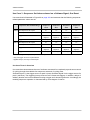
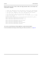
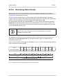
Fig. 41: Analog External Signal and Associated Internal Line Status with Propagation Delays for Opto-isolated Input
and Direct-coupled GPIO Inputs (Line Inverters Disabled)
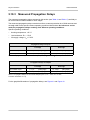
Basler ace USB 3.0
71