1
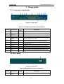
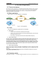
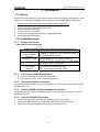
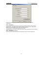
Raisecom Technology Co., Ltd
ISCOM4300
EOS (Ethernet over SDH) User
Manual
Raisecom Technology Co., Ltd
02/2005
Raisecom Technology Co., Ltd
Contents
1.
Overview........................................................................................................................ 3
1.1.
1.2.
1.3.
2.
Parameters .................................................................................................................... 5
2.1.
2.2.
2.3.
2.4.
2.5.
2.6.
2.7.
2.8.
3.
Front panel explanation .......................................................................................... 6
Rear panel .............................................................................................................. 6
Function & Application ................................................................................................... 7
4.1.
4.2.
4.3.
4.4.
5.
Basic configuration ................................................................................................. 5
Optical interface parameters .................................................................................. 5
Ethernet interface ................................................................................................... 5
CONSOLE interface ............................................................................................... 5
SNMP interface ...................................................................................................... 5
Clock ...................................................................................................................... 5
Power supply.......................................................................................................... 5
Ambience ............................................................................................................... 5
Usage guide .................................................................................................................. 6
3.1.
3.2.
4.
Main features.......................................................................................................... 3
Part number explanation ........................................................................................ 3
Dimension .............................................................................................................. 4
Process mechanism ............................................................................................... 7
Basic application .................................................................................................... 7
Clock ...................................................................................................................... 7
Protection switch .................................................................................................... 7
Installation ..................................................................................................................... 9
5.1. Notice ..................................................................................................................... 9
5.2. Installation steps..................................................................................................... 9
5.2.1
Prepare the cables .......................................................................................... 9
5.2.2
Connect the 155M SDH interface.................................................................... 9
5.2.3
Connect the Ethernet interface........................................................................ 9
5.2.4
Connect SNMP network management interface.............................................. 9
5.2.5
Connect CONSOLE interface.......................................................................... 9
5.2.6
Power on ....................................................................................................... 10
6.
Q & A ........................................................................................................................... 11
7.
Appendix: Making CONSOLE cable ............................................................................ 12
Raisecom Technology Co., Ltd
1. Overview
ISCOM4300 is a compact high-density Ethernet-over-SDH network edge access platform. It
is designed for fully utilizing the existing SDH network resources to provide subscribers with
SLA MAN or even WAN Ethernet access service. It introduces standard encapsulation
technology and advanced VCG/LCAS. This is a more Ethernet-service-specialized MSTP
technology, which cannot only communicate with existing MSTP, but also provide dynamic
adjustable dedicated network/line access on N*VC12/N*VC3 bandwidth. It decreases the
cost of access for subscribers, and increases the network resource utilization for operators.
In the initial period of MSTP deployment, it provides operators with secure, effective, easy,
and simple solutions for MAN/WAN Ethernet dedicated line service.
1.1. Main features
z
z
z
z
z
z
z
z
z
Provide two STM-1 interfaces and can be configured as 1+1 protection mode and
two-way independent mode;
Support the virtual concatenation of VC12 and VC3, the service bandwidth is adjustable,
maximum granularity is 2M and the maximum jitter between VCG members can be
24ms.
Support LCAS function;
Provide 16 Ethernet interfaces and support 3 types of encapsulation: GFP, LAPS and
PPP.
Master/slave clock mode supports clock holding, locking, and free running compliant
with G.813 standard.
Provide SNMP and CONSOLE network management interfaces and ECC embedded
channel, available for both local and remote field upgrade and is very convenient for
maintenance.
Provide fault alarm and performance monitor, optical interface and E1 interface provide
loop back function for convenient equipment maintenance.
Total power consumption <25W, high reliability
Temperature: -5 – 50 ℃
1.2. Part number explanation
Part number: ISCOM4300-X-Y
Explanation:
ISCOM4300: Raisecom series EOS equipments
155: STM-1 speed
X: optical connector mode, M/S1/S2/S3, please refer to table 1-1:
M: 0-2km
S1:0-25km
S2:10-60km
S3:15-120km
Y: power supply type, AC/DC:
AC: 220V
DC:-48V
Table 1-1 ISCOM4300 optical connector
Rate
Mbps
Type
Connector
Wave
length
nm
STM-1
M
SC
1310
S1
SC
1310
TX
power
dBm
-18-14
-15- -8
Over
load
point
dBm
-14
-8
Optical RX
sensitivity
dBm
(BER=E-1
0)
Typical
transmission
distance
Km
Optical
loss
dB/Km
< -29
0- 2
3
< -34
0- 25
0.5
Raisecom Technology Co., Ltd
S2
SC
1310
S3
SC
1550
-5- 0
-50(DFB)
-8
-10
< -34
10- 60
0.5
< -36
15- 120
0.25
1.3. Dimension
OPCOM4300 adopts international 19-inch chassis and is convenient for installation.
Dimension: 440(W)*43.6(H)*235(D)
4
Raisecom Technology Co., Ltd
2. Parameters
2.1. Basic configuration
● Main circuit board: 16 FE interfaces and two STM-1 optical interfaces
● Power supply module: 220VAC or –48VDC;
●Management interface: CONSOLE, SNMP network management interface
2.2. Optical interface parameters
●Rate: 155.52Mb/s
●Line coding: NRZ
●Connector type: SC
●Virtual concatenation: VC12 and VC3
●LCAS
2.3. Ethernet interface
●Rate:10/100M auto negotiation
●Connector: RJ-45
●IEEE802.3
●IEEE802.3x PAUSE flow control
●Support AUTO-MIDX auto sensing
●Encapsulation: LAPS, GFP and PPP
2.4. CONSOLE interface
●Connector: RJ-45
●Compliant with RS232
●Rate: 9600bps
2.5. SNMP interface
●Connector: RJ-45
●IEEE802.3
●10/100M auto negotiation
●Support AUTO-MIDX auto sensing
2.6. Clock
●Locking, holding and free running
●Frequency accuracy:
Free running: ≤±4.6×10⁻⁶ (According to G.811 basic clock)
Holding: ≤±0.37×10⁻⁶ (24 hours)
●Clock capture and unlock range: ≥±4.6×10⁻⁶
2.7. Power supply
● Power supply voltage: DC -48V, range: –36V- -72V
AC 220V, range: 180V- 260V
●Power consumption: <25W
2.8. Ambience
●Temperature: -5℃-50℃
●Humidity: ≤90% (35℃)
5
Raisecom Technology Co., Ltd
3. Usage guide
3.1. Front panel explanation
Figure 3.1 front panel
Table 3-1 front panel explanations of ISCOM4300
Number
1
Explanation
3, 5
6
7
8
nd
and 2
1
optical port
LOS indicator
Ethernet
interface and
indicator
LNK/ACT
indicator
100M indicator
STM-1 optical ports
Red
Green
Green
Green
10
11
SNMP
interface
CONSOLE
ALM
12
SYS
Red
Green
13
PWR
Green
9
Description
Grounding
st
2, 4
Indicator
color
ON, loss of signal; OFF, normal
1-16 Ethernet interfaces. There are two indicators for each
interface: LNK/ACT and 100M.
LNK/ACT indicator for SNMP. ON indicates connection is
good and flashing indicates data is being transmitting.
100M indicator for SNMP, ON indicates the interface is
working at 100M.
SNMP network management interface, RJ-45 connector
Local management interface connects to PC serial interface
General alarm indicator, ON when there is any alarm
System indicator, flashing indicates system works normal
Power supply indicator, ON indicates working well
3.2. Rear panel
Figure 3-2 rear panel
Table 3-2 ISCOM4300 rear panel explanation
Number
1
Explanation
Power supply
interface
Indicator
color
Description
220V AC, or -48V DC
6
Raisecom Technology Co., Ltd
4. Function & Application
4.1. Process mechanism
The service process mechanism is: encapsulate ingress Ethernet frames by GFP, LAPS or
PPP, map the encapsulated frames to VCG, and then transmit them through SDH/MSTP
network to the other end. In the other end of network, unencapsulate GFP/LAPS/PPP
frames and forward to Ethernet ports.
4.2. Basic application
Refer to figure 4-1 for basic application of ISCOM4300:
Figure 4-1 basic application
4.3. Clock
The clock of ISCOM4300 is compliant with G.813 standard.
1.
2.
Clock mode
9
Locking: clock is locked with outside input clock signal.
9
Holding: clock module will work at the last input signal frequency when the input
clock signal reference is lost.
9
Free running: clock module will work at the inside oscillator frequency.
Clock source select
The clock mode of OPCOM4300 is related to master/slave station. Master station uses free
running mode and slave station uses recovered clock. For slave station, there are two
recovered clock references: the first optical line (primary reference clock) and the second
optical line (standby reference clock). OPCOM4300 will switch the reference clock from the
first optical line to the second if the primary reference clock is not available (including there
is LOS and the frequency offset is more than 4.6ppm), and if the primary reference clock
has recovered it will switch back.
3.
Clock source switching
There won’t be error bit and too much jitter if OPCOM4300 is forced to switch from master
station to slave station or from slave station to master station, and it is compliant with ITUT
standard.
Every index is compliant with ITUT standard when OPCOM4300 changes the recovered
clock reference (e.g. if there is LOS)
4.4. Protection switch
OPCOM4300 provides 1+1 multiplex segment protection and can be configured as not
7
Raisecom Technology Co., Ltd
switching, automatic protection switch and force protection switch by network management
system. The conditions of automatic protection switch are as follows: SPI-LOS, RS-LOF,
MS-AIS, MS-EXC, and MS-SD, RS-TIM optional.
For 1+1 multiplex segment protection, the protection switching only happens at RX end.
Optical port 1 is working channel and optical port 2 is protection channel.
Switching restore is configured by network management, and the protection restore
happens after the optical line works well for 5-12 minutes, the waiting time is configured by
network management (range is 5-12 minutes)
8
Raisecom Technology Co., Ltd
5. Installation
5.1. Notice
Please check the equipment, part number and the number according to package list, check
whether the equipment is damaged. If the equipment is affected by damp, please dry it.
●
●
●
●
●
●
Please follow the following steps for installation and configuration:
Read this manual carefully
Prepare the optical fiber and Ethernet cable
Fix and install the equipment
Connect the fiber or the cable
Configure the equipment according to configuration guide
User the equipment normally
5.2. Installation steps
5.2.1
Prepare the cables
Cables need to be prepared are:
Table 5-1 Specifications of the cables that need to be prepared
Interface
Cable specification
10/100Mbps Ethernet
100Base-T category-5 UTP, maximum length is
ports and SNMP
100 m.(Provided by users)
interface
CONSOLE
cable
Optical patch cord
Power supply
interface
5.2.2
●
●
5.2.3
Refer to appendix.(Provided by Raisecom)
SC/SC or SC/FC, single mode or multi mode
according to user’s requirement.
AC, 220V/10A power supply cable.
DC, - -48V/10A power supply cable.
Connect the 155M SDH interface
Connect 155M SDH interface with optical fiber
LOS indicator is OFF if the connection is correct.
Connect the Ethernet interface
Connect the Ethernet cable with Ethernet interface, if the connection is good the LNK/ACT
indicator will be ON.
5.2.4
Connect SNMP network management interface
Connect the Ethernet cable with SNMP interface, if the connection is good the LNK/ACT
indicator will be ON.
5.2.5
●
●
●
Connect CONSOLE interface
Connect the CONSOLE interface with RJ45 connector of the cable.
Connect the DB9 connector of CONSOLE cable with PC’s serial interface.
Start Hyper Terminal program on PC and the configurations are:
9
Raisecom Technology Co., Ltd
Please refer to the network management user manual for network management
configuration
5.2.6
Power on
If you use -48V DC as power supply, connect the “grounding connector” with protection
grounding first, “-48V” with low level voltage cable and “0V”with high level voltage cable.
Make sure of firm installation and no short-circuit, then power on.
If you use 220V AC, use the affixing power supply cable.
After powered on, PWR indicator light will be normal, and the system has finished initialized
if SYS starts to flick
5.2.7
Configure the services
Please refer to the command guide and configuration guide for service configuration
10
Raisecom Technology Co., Ltd
6. Q & A
If you have problems during the installation or application, please try to solve them through
the following suggestions. And if it does not work, please contact sales to get technical
supports.
● PWR indicator turns OFF.
Check the power supply cable first, and then the power supply card.
● LOS alarms of SDH optical interface
That is to say, there is receiving signal loss. First, check whether the cable is connected
correctly; second, if there are still alarms when self-loop the cable (perhaps optical
attenuation is needed), change the cables; if there are still alarms then there is something
wrong with device.
● Indicator light of Ethernet interface or SNMP network management interface is OFF.
First, check whether the cable works normally or not; then, check whether the devices
connect to Ethernet interface or SNMP network management interface works normally or
not. And make sure the cable is correct.
11
Raisecom Technology Co., Ltd
7. Appendix: Making CONSOLE cable
CONSOLE interface cable
CONSOLE interface uses RJ45 connector and the pin definition is as follows:
RJ-45 Pin number
Signal
Relative PC Pin number
1
NC
2
DSR#
6
3
RxD
3
4
GND
5
5
GND
5
6
TxD
2
7
DTR#
4
8
NC
-
“-” indicates not connect
12
Raisecom Technology Co., Ltd
@2005 Raisecom Technology Co., Ltd.
All trademarks are the property of their respective owners.
Technical information may be subject to change without prior notification.
13