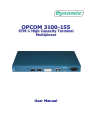
1
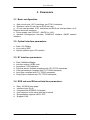
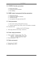
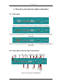
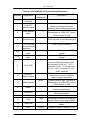
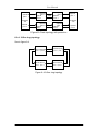
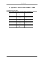
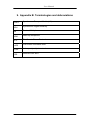
OPCOM 3100-155 STM-1 High Capacity Terminal Multiplexer User Manual User Manual 1. Cautions Please read the following notices carefully before installing and using OPCOM3100-155 multiplexer . There must be grounding protection for the sake of safety; the installing, maintaining and plugging/pulling must be operated by technical staff following in steps of anti static. OPCOM3100 must be installed in the equipment center where temperature and humidity are proper, and please be attention to the electric features of surrounding devices. There are high sensitivity optical fittings inside the device, so the power of network device’s optical output interface must be checked before connecting. To avoid damaging, it is not allowed that the optical power of network device’s output interface is higher than that of OPCOM3100. OPCOM3100 is integrated device that has precise elements, please avoid violent shakes and impacts, and do not disassemble or maintain the device yourself, we regard it as you waiver your rights of repair guarantee. 1 User Manual Contents 1. 2. 3. 4. 5. 6. Cautions.............................................................................................................. 1 Overview............................................................................................................. 4 2.1. Main feathers ........................................................................................... 4 2.2. Explanation of device number: ................................................................. 5 2.3. Part number explanation: ......................................................................... 5 2.4. Power number explanation: ..................................................................... 5 2.5. Dimension: ............................................................................................... 5 Parameters ......................................................................................................... 6 3.1. Basic configuration................................................................................... 6 3.2. Optical interface parameters: ................................................................... 6 3.3. E1 interface parameters: .......................................................................... 6 3.4. EOS sub card Ethernet interface parameters:.......................................... 6 3.5. CONSOLE interface parameters .............................................................. 7 3.6. SNMP network management interface parameters:................................. 7 3.7. Clock parameters: .................................................................................... 7 3.8. Power supply parameters: ....................................................................... 7 3.9. Work environment: ................................................................................... 7 Structure and indicator lights explanation ........................................................... 8 4.1. Front panel ............................................................................................... 8 4.2. Front panel indicator lights explanation: ................................................... 8 4.3. Rear panel view: .................................................................................... 10 Function and application ....................................................................................11 5.1. Network element type .............................................................................11 5.2. Network topology ................................................................................... 12 5.3. Clock ...................................................................................................... 13 5.4. Protection switch .................................................................................... 14 Installation & Preparation .................................................................................. 17 6.1. Cautions ................................................................................................. 17 6.2. Installation .............................................................................................. 17 6.2.1. Cable preparation.......................................................................... 17 6.2.2. Install the extension slot ................................................................ 17 6.2.3. Connect 155M SDH interfaces...................................................... 18 6.2.4. Connect E1 electrical port ............................................................. 18 6.2.5. Connect Ethernet port(If there is Ethernet service) ....................... 18 6.2.6. Connect SNMP network management port ................................... 18 6.2.7. Connect CONSOLE port ............................................................... 18 6.2.8. Power on ....................................................................................... 19 6.2.9. Service configuration..................................................................... 19 6.3. Connections ........................................................................................... 19 6.3.1. Point-to-point topology .................................................................. 20 6.3.2. Chain topology without protection ................................................. 20 6.3.3. Chain topology with protection ...................................................... 20 2 User Manual 7. 8. 9. 6.3.4. 2-fiber ring topology ...................................................................... 21 Q & A ................................................................................................................ 22 Appendix A: How to make CONSOLE cable..................................................... 23 Appendix B: Terminologies and abbreviations .................................................. 24 3 User Manual 2. Overview OPCOM3100-155 is compact SDH Multi-Service access equipment developed by Dynamix , technical feature and indexes meet every norm of ITU-T and national SDH. It deploys 1U structure, and it can provide STM-1, E1 and Ethernet service. It is suitable for the access of end business of Telecom. OPCOM3100-155 is mainly applied to service access and transmission of access layer in communication networks; it also can make up communication networks through E1 interface together with access devices, GSM mobile cellular base station, ETS wireless access base station, switches and routers. OPCOM3100-155 is available for flexible topology: point-to-point, chain and ring and supports 1+1 low path protection to guarantee high reliable transportation. 2.1. Main feathers Provide two STM-1 interfaces, with options of either two individual STM-1 or 1+1 path protection; The device consists of main card and sub card, and the main card provides 16 E1 interfaces and sub card provides 4/8 Ethernet interfaces or 16 E1 interfaces. Ethernet interface supports encapsulation of GFP and LAPS, the minimum service bandwidth is 2M, it also supports VCG/LCAS and the bandwidth can be adjusted without any damage for customer need. Support 126*126 VC12 non-blocking cross capability. Network Element type: TM, ADM or REG. Network topology type: point-to-point, chain and ring; provide 1+1 low path protection, and the switch time is less than 50ms. Master/slave clock mode supports clock holding, locking, and free running compliant with G.813 standard. Provide SNMP and CONSOLE network management interfaces and ECC embedded channel, available for both local and remote field upgrade and is very convenient for maintenance. Provide fault alarm and performance monitor, optical interface and E1 interface provide loop back function for convenient equipment maintenance. Support three types of power supply: 220V, -48V and +24V 4 User Manual Power consumption: <15W. Temperature: -5 ~50°C 2.2. Explanation of device number: OPCOM3100-155 consists of main card, extension card and power card, and the extension card includes E1 sub card and EOS sub card. Whole device type number: OPCOM3100-155 Explanation: OPCOM3100 stands for RC 1U series SDH transmission platform and 155 stands for the rate of STM-1. 2.3. Part number explanation: Type OPCOM3100-155-SC-E1 OPCOM3100-155-SC-FE-4TX OPCOM3100-155-SC-FE-8TX Explanation E1 sub card, provide 16 E1 interfaces EOS sub card, provide 4 Ethernet electrical interfaces EOS sub card, provide 8 Ethernet electrical interfaces 2.4. Power number explanation: Type OPCOM3100-155-PWR-AC OPCOM3100-155-PWR-DC48 OPCOM3100-155-PWR-DC24 Explanation 220V AC -48V DC +24V DC 2.5. Dimension: OPCOM3100-155 adopts international 19-inch chassis and is convenient for installation. Dimension: 440(W)*43.6(H)*266(D) 5 User Manual 3. Parameters 3.1. Basic configuration ● Main circuit card: 16 E1 interfaces, two STM-1 interfaces; ● Extension card: E1 sub card or EOS sub card; ● E1 sub card provides 16 E1 interfaces and EOS sub card provides 4 or 8 Ethernet electrical interfaces; ● Power supply card: 220VAC, –48VDC or +24V; ● Network management interface: CONSOLE interface, SNMP network interface; 3.2. Optical interface parameters: ● Rate: 155.52Mb/s ● Line coding: NRZ ● Optical interface type: SC interface 3.3. E1 interface parameters: ● ● ● ● ● ● ● Rate: 2048Kb/s±50ppm Interface coding: HDB3 code Impedance: 75Ω/unbalance Physical electric feathers compliant with ITU-TG.703 standards; Jitter performance compliant with ITU-TG.823 standards; Input jitter compliant with ITU-TG.823 standards; Output jitter compliant with ITU-TG.783 standards; 3.4. EOS sub card Ethernet interface parameters: ● ● ● ● ● ● Rate: 10/100 M auto-adapt Interface type: RJ-45 Compliant with IEEE802.3 standard Line sequence is the same with that of switch Encapsulation supports LAPS, GFP Support LCAS 6 User Manual 3.5. CONSOLE interface parameters ● Interface type: RJ-45 ● Compliant with RS232 standard ● Rate: 9600bps 3.6. SNMP network management interface parameters: ● ● ● ● Interface type: RJ-45 Compliant with IEEE802.3 standard 10/100M auto-adapt Line sequence is the same with that of PC 3.7. Clock parameters: ● Clock mode: Locking, holding and free running ● Frequency precision: free running: ≤±4.6×10⁻⁶(relative to traceable G.811 standard clock) Holding: ≤±0.37×10⁻⁶(24 hours) ● Trace range and loss of lock range: ≥±4.6×10⁻⁶ 3.8. Power supply parameters: ● Voltage: -48V DC, tolerance range: -36V~-72V +24V DC, tolerance range: +18V~+36V 220V AC, tolerance range: 180V~260V ● Power consumption: <15W 3.9. Work environment: ● Temperature:-5°C~50°C ● Humidity: ≤90 %( 35°C) 7 User Manual 4. Structure and indicator lights explanation 4.1. Front panel Figure 4-1 front panel with DC power supply and 32 E1 interfaces Figure 4-2 front panel with DC power supply, 16 E1 interfaces and 4 Ethernet interfaces Figure 4-3 front panels with DC power supply, 16 E1 interfaces and 8 Ethernet interfaces 4.2. Front panel indicator lights explanation: 4 2 1 3 5 8 6 11 15 12 9 19 14 7 17 18 10 13 16 20 Figure 4-4 front panel explanations 8 21 User Manual Table 4-1 OPCOM3100-155 front panel explanations Number Explanation 1 Grounding interface 2 LNK/ACT indicator lights 3 100M indicator lights 4 Extension slot 5,8 6,9 7,10 The first and second optical interfaces LOS indicator lights LOF indicator lights 11 1-8,9-16 E1 12 LNK/ACT indicator lights Indicator lights color Description Green Ethernet indicator light. ON: Ethernet connection normal; Flashing: data is being transmitted. Ethernet indicator light. ON: rate of Ethernet port is 100M, OFF: rate of Ethernet port is 10M For E1 sub card of 16 E1 port s or EOS sub card of 4/8 Ethernet port s STM-1 optical interface Orange Red ON: loss of optical signal; OFF: normal ON: loss of SDH frame; OFF: normal For the Rx and Tx of 1-16 E1 channel 2mmHM connector. And the sequence is: Rx of 1 8 E1 channels, Tx of 1 8 E1 channels, Rx of 9 16 E1 channels, Tx of 9 16 E1 channels SNMP interface indicator light. ON: connection is normal; Flashing: data is being transmitted SNMP indicator light. ON: rate of Ethernet port is 100M, OFF: rate of Ethernet port is 10M Ethernet port which provides network management Local control platform connected to PC serial interface Reset Whole alarm indicator, the light will be ON if there is any kind of alarm ON: master station; OFF: slave station System indicator, Flashing: CPU Red Green Green 13 100M indicator 14 SNMP 15 CONSOLE 16 RST 17 ALM 18 MASTER 19 SYS Red Green Green 9 User Manual 20 PWR 21 -48V power supply inlet works normally Power supply indicator, ON: power supply works normally Power supply type: 220V AC, -48V DC, +24V DC Green 4.3. Rear panel view: Figure 4-5 rear panel view 10 User Manual 5. Function and application 5.1. Network element type OPCOM3100-155 is suitable for network end access. It can provide STM-1, E1 and Ethernet access and can be configured as TM, ADM and REG. 1. Terminal multiplexer (TM) The main function of terminal multiplexer (TM) is multiplexing low speed E1 or Ethernet signal to high speed STM-1 SDH signal and demultiplexing high speed STM-1 SDH signal to low speed E1 or Ethernet signal. STM-1 optical signal E1 electrical signal/Ethernet signal Figure 5-1 TM network element type 2. Add/Drop multiplexer (ADM) Add/Drop multiplexer (ADM) is the most common network element type in SDH network, it has both synchronous multiplexing function and digital cross connection function, and can add/drop the tributary signal flexibly. For example the access E1 signal can be multiplexed to both east STM-1 signal and west STM-1 signal. STM-1 optical signal STM-1 optical signal E1 electrical signal/ Ethernet signal Figure 5-2 ADM network element type 11 User Manual 3. Regenerator REG Regenerator REG can compensate the optical attenuation caused by transmission fiber and regenerate new optical signal for transmission. 5.2. Network topology OPCOM3100-155 has flexible networking capacity and high transmission reliability, and it provides both 1+1 path protection and 2F SNC-P protection. 1. Point-to-point network consists of 2 TM devices and transmits STM-1, E1 and Ethernet services. STM-1 optical signal TM E1 electrical signal/ Ethernet signal TM E1 electrical signal/ Ethernet signal Figure 5-3 point-to-point topology 2.Chain topology Chain topology is made up of two TM devices and several ADM devices. Data is often transmitted in bi-direction and less optical fiber is needed. TM STM-1 optical signal E1 electrical signal/ Ethernet signal ADM STM-1 optical signal E1 electrical signal/ Ethernet signal Figure 5-4 chain topology 3. Ring topology 12 TM E1 electrical signal/ Ethernet signal User Manual OPCOM3100-155 can organize ring topology network at STM-1speed with flexible service configuration and high reliability, it also can realize 2F SNC-P function. E1 electrical signal/Ethernet signal ADM E1 electrical signal/Ethernet signal ADM STM-1 ring ADM E1 electrical signal/Ethernet signal ADM E1 electrical signal/Ethernet signal Figure 5-5 ring topology 5.3. Clock Clock of OPCOM3100-155 is compliant with G.813 standard. 1 Clock mode ● Locking: clock is locked with outside input clock signal. ● Holding: clock module will work at the last input signal frequency when the input clock signal reference is lost. ● Free running: clock module will work at the inside oscillator frequency. 2 Clock source select The clock mode of OPCOM3100 is related to master/slave station. Master station uses free running mode and slave station uses recovered clock. For slave station, there are two recovered clock references: the first optical line (primary reference clock) and the second optical line (standby reference clock). OPCOM3100 will switch the reference clock from the first optical line to the second if the primary reference clock is not available (including there is LOS and the frequency offset is more than 4.6ppm), and if the primary reference clock has recovered it will switch back. 3 Clock source switching There won’t be error code and too much jitter if OPCOM3100 is forced to switch from master station to slave station or from slave station to master 13 User Manual station, and it is compliant with ITUT standard. Every index is compliant with ITUT standard when OPCOM3100 change the recovered clock reference (e.g. if there is LOS) 5.4. Protection switch OPCOM3100 provides 1+1 low path protection in the case that the optical fiber is broken off, PCB is damaged or middle notes are invalid, and the protection switch time will be less than 50ms. There are two kinds of protection switch: automatic protection switch and force protection switch, the force protection switch can be configured through network management. The conditions of automatic protection switch are as follows: Switch type Path protection Switch conditions TU_AIS, TU_LOP TU_AIS, TU-LOP are caused by: Segment: SPI-LOS, RS LOF, MS-AIS, MS-EXC, MS-SD (optional); AU:AU-AIS,AU-LOP; HP:HP-LOM, HP-EXC, HP-SD (optional); 1. Protection switch in chain topology: Optical port 1 Optical port 2 OPCOM3100 -155 work OPCOM3100 -155 OPCOM3100 -155 protect OPCOM3100 -155 Optical port 1 Optical port 2 As the above figure, in chain 1+1 path protection between two ends, there are two transmission lines transmitting the data, and every note receives the data twice. One of the transmitting lines is working line and the other one is protection line. Receiving end will select a better quality signal from the two lines. Generally the Rx data is from working line and if there is protection switch the Rx data is from protection line. When the working line has recovered the Rx data is from working line again. 14 User Manual 2. 2F SNC-P: The principle of 2F SNC-P protection is that: “transmit data bi-directionally, receive data bi-directionally, select one better quality signal and use the other signal as standby”. 2F SNC-P uses one fiber to transmit service, called S fiber (working fiber); uses another fiber for protection, called P fiber (protection fiber). If every note of the ring works normally, the direction Tx signal and Rx signal is the same (that is to say, if a note transmits data clockwise so does it receives data), but the routing is not the same (e.g. if station A transmits data to station C, the routing is A→B→C; and if station A receives data from C, the routing is C→D→A, so the middle stations passed by are not same). See in the following figure: CA AC S P A B D C P S (a) CA AC CA AC S P A B D C P S (b) CA AC switch The Tx and Rx routing is in figure (a) when it works normally: data from A to C is transmitted both in S fiber and P fiber, S fiber will transmit the data from A to C clockwise though middle station B, and P fiber will transmit the data from A to 15 User Manual C anticlockwise though middle station D. C receives two signals bi-directionally and it will select a better quality signal (the signal in working line S fiber generally). Data from C to A is the same process. The Tx and Rx routing is in figure (b) when the fiber is cut off: for the signal in S fiber is lost the switch will shift from S fiber to P fiber to receive the data transmitted by P fiber, so the service between station A and C will go on. After 5~12 minutes the switch will recover if the fault is resolved and the service from C to A will not be effected. 16 User Manual 6. Installation & Preparation 6.1. Cautions Check whether the type of device, spare parts and number are same with that of packing list. Make sure the device appearance is in excellent condition. There must be drying process if the device has been damp. To make sure normal working of the device, please follow the following steps: ● Read this manual carefully ● Fix and install the device ● Prepare the fiber and E1 cable ● Connect the fiber or other cables ● If this is your first use of the device, please refer to configuration manual and command manual. ● Use the device properly 6.2. Installation 6.2.1. Cable preparation The cables you need to prepare are: Table 6-1 OPCOM3100-155 cable specifications Interface Specifications 10/100Mbps Ethernet 100Base-T category-5 UTP, the maximum distance is electrical 100m.(users provide) interface/SNMP interface CONSOLE cable Optical fiber E1cable Power supply interface Refer to appendix. Multi mode fiber or single mode fiber with SC/SC or SC/FC connector (customized) Special 2mmE1 cable. AC, 220V/10A power supply cable. -48V DC, -48V/10A power supply cable. +24VDC, +24V/10A power supply cable. 6.2.2. Install the extension slot E1 and EOS sub card can insert into extension slot and cannot hot-swap. 17 User Manual 6.2.3. Connect 155M SDH interfaces ● Connect the fiber to the SDH interfaces on front panel. ● If proper connected the LOS indicator light will turn off. Please refer to 6.3 6.2.4. Connect E1 electrical port Connect E1 electrical port (2MM) through E1 cable with other device. Each E1 cable has 8 E1 IN or OUT pins in one end and the other end has 8 BNC connectors, each connector has a number stands for the first channel to the eighth channel. 6.2.5. Connect Ethernet port(If there is Ethernet service) Connect the Ethernet port through Ethernet cable with router or Ethernet switch and the LNK/ACT will ON if the connection is correct. 6.2.6. Connect SNMP network management port Connect the SNMP network management port through Ethernet cable with related device and the LNK/ACT will ON if the connection is correct. 6.2.7. Connect CONSOLE port ● ● ● Connect the RJ45 connector of CONSOLE cable with CONSOLE interface on the front panel. Connect the DB9 connector PC serial interface. Start Hyper Terminal on PC: 18 User Manual ● Configure the network management of OPCOM3100-155; please refer to command manual and configuration manual of OPCOM3100-155. 6.2.8. Power on If you use -48V DC as power supply, connect the ground with protection grounding first, “-48V” with low level voltage cable and “0V”with high level voltage cable. Make sure of firm installation and no short-circuit, then power on. If you use 220V AC, use the affixing power supply cable. After powered on, PWR indicator light will be normal, and the system has finished initialized if SYS starts to flick 6.2.9. Service configuration OPCOM3100 support time slot configuration of VC12 level, please refer to command manual and configuration manual. 6.3. Connections Different topology has different connection methods, and different protection mode also has different connection methods. 19 User Manual 6.3.1. Point-to-point topology Point-to-point topology is very simple and the connection method will not change. See in the following figure: Optical port 1 Optical port 1 OPCOM3100 -155 OPCOM3100 -155 Optical port 2 Optical port 2 Figure 6-1 Point-to-point topology 6.3.2. Chain topology without protection See in figure 6-2. Optical port 1 Optical port 1 Optical port 1 Optical port 1 OPCOM3100 -155 OPCOM3100 -155 OPCOM3100 -155 OPCOM3100 -155 Optical port 2 Optical port 2 Figure 6-2 Chain topology without protection 6.3.3. Chain topology with protection See in figure 6-3. 20 User Manual Optical port 1 Optical port 1 Optical port 2 work Optical port 1 Optical port 2 OPCOM3100 -155 OPCOM3100 -155 Optical port 2 Optical port 1 Optical Optical port 1 port 1 protect Optical Optical port 2 port 2 Figure6-3 Chain topology with protection 6.3.4. 2-fiber ring topology See in figure 6-4. Optical Optical port 1 port 2 Optical Optical port 1 port 2 Optical Optical port 2 port 1 Optical Optical port 2 port 1 Figure 6-4 2-fiber ring topology 21 Optical port 2 User Manual 7. Q & A If you have problems during the installation or application, please try to solve them through the following suggestions. And if it does not work, please contact the sellers to get technical supports. ● PWR light of power supply card turns OFF. Check the power supply cable first, and then the power supply card. ● LOS alarms of SDH optical interface That is to say, there is receiving signal loss. First, check whether the cable is connected correctly; second, if there are still alarms when self-loop the cable (perhaps optical attenuation is needed), change the cables; if there are still alarms then there is something wrong with device. ● Indicator light of Ethernet interface or SNMP network management interface is OFF. First, check whether the cable works normally or not; then, check whether the devices connect to Ethernet interface or SNMP network management interface works normally or not. And make sure the cable is correct. ● E1 channel failed Check the E1 cable, optical interface and time slot configuration, check the alarms in the EMS and use loop back function to find where the problem is. 22 User Manual 8. Appendix A: How to make CONSOLE cable ● CONSOLE interface cable CONSOLE interface uses RJ45 connector and the pin definition is as follows: RJ-45 Pin Signal Relative PC Pin number number 1 NC 2 DSR# 6 3 RxD 3 4 GND 5 5 GND 5 6 TxD 2 7 DTR# 4 8 NC - 23 User Manual 9. Appendix B: Terminologies and abbreviations STM-1 SDH TM ADM GFP LAPS LCAS EOS Synchronous Transport Module (-N) Synchronous Digital Hierarchy Terminal Multiplexer Add/Drop Multiplexer The Generic Frame Protocol Link Access Procedure SDH Link capacity adjustment scheme Ethernet Over SDH 24