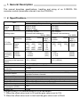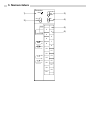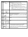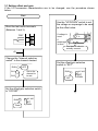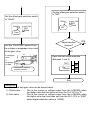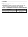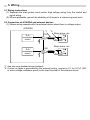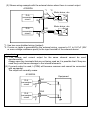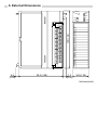
1
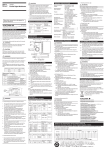
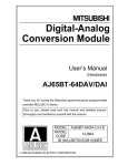
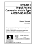
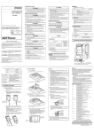
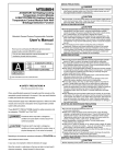
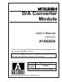
D/A Converter
Module
User’s Manual
(Hardware)
A1S62DA
Thank you for buying the Mitsubishi general-purpose programmable
logic controller MELSEC-A Series
Prior to use, please read both this manual and detailed manual
thoroughly and familiarize yourself with the product.
MODEL A1S62DA(H/W)-U-E
MODEL
13JE43
CODE
IB (NA)-66482-D(0609) MEE
©1994 MITSUBISHI ELECTRIC CORPORATION
z SAFETY PRECAUTIONS z
(Always read before starting use)
When using Mitsubishi equipment, thoroughly read this manual and the
associated manuals introduced in the manual. Also pay careful attention to
safety and handle the module properly.
These precautions apply only to the installation of Mitsubishi equipment and the
wiring with the external device. Refer to the user’s manual of the CPU module
to be used for a description of the PLC system safety precautions.
These
SAFETY PRECAUTIONS
classify the safety precautions into two
categories: "DANGER" and "CAUTION".
DANGER
Procedures which may lead to a dangerous condition and
cause death or serious injury if not carried out properly.
CAUTION
Procedures which may lead to a dangerous condition and
cause superficial to medium injury, or physical damage
only, if not carried out properly.
Depending on circumstances, procedures indicated by
CAUTION may also
be linked to serious results.
In any case, it is important to follow the directions for usage.
Store this manual in a safe place so that you can take it out and read it
whenever necessary. Always forward it to the end user.
[DESIGN PRECAUTIONS]
DANGER
z Install a safety circuit external to the PLC that keeps the entire system safe
even when there are problems with the external power supply or the PLC
module. Otherwise, trouble could result from erroneous output or
erroneous operation.
(1) The analog output state will differ according to the setting state of the
various functions for controlling the analog output.
For details, refer to manual Section 3.4.4 on the analog output state.
(2) If there is a fault in the output element or the internal circuit, correct
outputs may not be possible or erroneous outputs may be made.
Provide a circuit to externally monitor output signals that could lead to
major faults.
CAUTION
z Do not bunch the control wires or communication cables with the main
circuit or power wires, or install them close to each other.
They should be installed 100mm (3.94inch) or more from each other.
Not doing so could result in noise that would cause erroneous operation.
z At power ON/OFF, voltage or current may instantaneously be output from
the output terminal of this module. In such case, wait until the analog
output becomes stable to start controlling the external device.
[INSTALLATION PRECAUTIONS]
CAUTION
z Use the PLC in an environment that meets the general specifications given in the
User’s Manual of the CPU module in use.
Using this PLC in an environment outside the range of the general specifications
could result in electric shock, fire, erroneous operation, and damage to or
deterioration on the product.
z Securely insert the module fixing latch on the module bottom into the fixing holes
on the base unit before mounting. Incorrect mounting of the module could lead to
erroneous operation, faults or drop.
[WIRING PRECAUTIONS]
CAUTION
z When wiring in the PLC, be sure that it is done correctly by checking the product’s
rated voltage and the terminal layout.
Connecting a power supply that is different from the rating or incorrectly wiring the
product could result in fire or damage.
z Tighten the terminal screws with the specified torque.
If the terminal screws are loose, it could result in short circuits, fire, or erroneous
operation.
z Be sure there no foreign substances such as sawdust or wiring debris inside the
module.
Such debris could cause fires, damage, or erroneous operation.
[STARTUP AND MAINTNANCE PRECAUTIONS]
DANGER
z Externally shut off all power phases before touching the terminals.
Failure to observe this could lead to erroneous operation.
z Be sure to shut off all phases of the external power supply used by the system
before cleaning or retightening the terminal screws.
Not doing so can cause the module to fail or malfunction.
CAUTION
z Do not dissemble or modify the module.
Doing so could cause trouble, erroneous operation, injury, or fire.
z Be sure to shut off all phases of the external power supply used by the system
before mounting or removing the module.
Not doing so may cause damage to the module.
z Do not install/remove the terminal block more than 50 times after the first use of the
product. (IEC 61131-2 compliant)
z Before handling the module, always touch grounded metal, etc. to discharge static
electricity from the human body.
Failure to do so may cause the module to fail or malfunction.
[DISPOSAL PRECAUTIONS]
CAUTION
z When disposing of the product, handle it as industrial waste.
About the Manuals
The following product are available for this equipment.
Refer to the table given below to choose suitable manuals.
Detailed Manual
Manual name
D/A converter module type A1S62DA User's Manual
Manual No.
(Model code)
IB-66335
Conformance to the EMC Directive/Low Voltage Directive
When incorporating the Mitsubishi PLC into other machinery or equipment and
keeping compliance with the EMC and low voltage directives, refer to Chapter 3,
"EMC Directives and Low Voltage Directives" of the User's Manual (Hardware)
included with the CPU module or base unit used.
The CE logo is printed on the rating plate on the main body of the PLC that conforms
to the EMC directive and low voltage instruction.
By making this product conform to the EMC directive and low voltage instruction, it is
not necessary to make those steps individually.
1. General Description
This manual describes specifications, handling and wiring of an A1S62DA D/A
converter module (hereinafter referred to as the A1S62DA).
2. Specifications
Item
Digital
input
1/4000
1/8000
1/12000
Analog output
Resolution
I/O characteristics
Digital
input
value
Maximum
1/4000
resolution
1/8000
of analog
1/12000
value
Overall accuracy
(accuracy to the maximum
value)
Maximum conversion time
Absolute maximum output
Output short circuit
protection
Analog output points
Isolation method
Number of I/O points
Connection terminal
Offset/gain adjustment
Applicable wire size
Applicable crimp terminal
Internal current
consumption (5VDC)
Weight (kg)
Specifications
Voltage Output
-4000 to 4000
-8000 to 8000
-12000 to 12000
-10 to 0 to 10 VDC
(External load resistance:
2KΩ to 1MΩ)
Analog
1/4000
1/8000
output
1/12000
value *1
4000 8000 12000
10V
2000 4000
6000
5V
0
0
0
0V
-2000 -4000
-6000
-5V
-4000 -8000 -12000
-10V
2.5mV
1.25mV
0.83mV
±1% (±100mV)
(10V)
(10V)
(10V)
Current Output
0 to 4000
0 to 8000
0 to 12000
0 to 20mADC
(External load resistance:
0 to 600Ω)
Analog
1/4000
1/8000
output
1/12000
value *2
4000 8000 12000
20mA
2000 4000
6000
12mA
0
0
0
4mA
5μA
2.5μA
1.7μA
(20mA)
(20mA)
(20mA)
±1% (±200μA)
Maximum 25ms/2 channels (same for 1 channel)
Voltage:±12V Current:+28mA
Provide
2 channels/module
Photocoupler insulation between output terminals and PLC power No
insulation between channels
32 points
20-points terminal block
By the test terminal (without using offset/gain adjusting knobs)
0.75 to 1.5mm2
1.25-3, 1.25-YS3A, V1.25-3, V1.25-YOS3A
0.8A
0.32kg
The gain is set to 10V and the offset to 0V as the default.
*1 When the offset value is set to 0V and the gain value is set to 10V.
*2 When the offset value is set to 4mA and the gain value is set to 20mA.
3. Nomenclature
A1S62DA
1)
2)
OFFSET
RUN
SET
GAIN
CH1
UP
CH2
DOWN
TEST
3)
4)
1
5)
3
6)
2
HLD/CLR
4
5
6
7
V+
V-
8
9
I+
I-
10
11
12
13
V+
V-
14
15
I+
I-
16
17
18
19
20
No
1)
Description
“RUN” LED
RUN
2)
Channel select switch
Application
Indicates the operating status of the A1S62DA.
(Normal mode)
On
:Indicates that the A1S62DA is functional.
Off
:The 5 VDC power is not supplied or A1S62DA is faulty.
Flash :When a digital value is written which is outside the high or
low limit, this LED flashes every second.
(Test mode)
Off
:OFFSET/GAIN select switch is in the “SET” position.
Flash :When the offset/gain select switch is set to either the
OFFSET or GAIN position, this LED flashes every half (0.5)
second.
When the offset or gain has reached the upper or lower
limit, this LED flashes every tenth (0.10) of a secind.
Used to specify a channel for the offset/gain adjustment.
CH1
CH2
3)
OFFSET/GAIN select
switch
OFF SET
SET
GAIN
4)
UP/DOWN switch
OFFSET position: Sets the offset value.
GAIN position: Sets the gain value.
SET position: The offset/gain value is stored to the A1S62DA
internal memory when the switch is moved from “OFFSET”/”GAIN”
to “SET”.
Increases or decreases the offset/gain value of the specified
channel.
UP
DOWN
5)
Test mode terminals
TEST
2
6)
1
3
Output HOLD/CLEAR
setting terminals
2
HLD/CLR
4
Connected between terminals No.1 and No.3 to set the offset/gain
values
3
Used to hold or clear the analog output at the time of CPU STOP.
Disconnected between terminal No.2 and No.4: CLEAR
Connected between terminal No.2 and No.4: HOLD
The analog output status of the HOLD/CLEAR setting varies with
the setting of the D-A conversion value output enable flag and the
analog output enable/disable state.
3.1 Setting offset and gain
If the I/O conversion characteristics are to be changed, use the procedure shown
below.
Start
Short the test mode terminals
(Between 1 and 3).
Use the "UP/DOWN" switch to set
the voltage or amperage to be used
as the offset value.
If voltage is
used.
TEST
V+
V
V-
If
A I+
amperage
Iis used.
Resistance value to
actually connect.
A)
Change the "channel selection
switch" to the channel desired.
RUN
CH1
OFF
Set to the
channel to
be set.
CH2
Set the offset/gain selection switch
to "OFFSET".
RUN
Flash
OFF SET
SET
GAIN
Set the offset/gain selection
switch to "SET".
RUN
OFF SET
SET
GAIN
OFF
1)
1)
Set the offset/gain selection switch
to "GAIN".
Set the offset/gain selection switch
to "SET".
RUN
OFF SET
RUN
SET
GAIN
Flash
Use the "UP/DOWN" switch to set
the voltage or amperage to be used
as the gain value.
V+
If voltage is
used.
If
amperage
is used.
V
V-
A I+
I-
OFF SET
SET
GAIN
OFF
Adjust another
channel?
YES
A)
NO
Open the test mode terminals
(Between 1 and 3).
TEST
Resistance value to
actually connect.
End
Reference
The offset value and gain value are as shown below.
1) Offset value ......... This is the current or voltage output from the A1S62DA when
the digital value that has been set from the PLC CPU is "0".
2) Gain value ........... This is the current or voltage output from the A1S62DA when
the digital value that has been set from the PLC CPU is "4000"
(when digital resolution value is 1/4000).
4. Handling
4.1 Precautions for handling
(1) The main body case and terminal block are made of resin, so do not drop them or
apply strong impacts.
(2) Do not remove the module PCB from the case. Doing so could lead to faults.
(3) Make sure that foreign matter, such as wire scraps, does not enter from the top of
the module during wiring. Remove any foreign matter that does enter.
(4) Tighten the module installation screws and terminal screws within the following
ranges.
Screw position
Module installation screw (M4 screw)
Terminal block terminal screw (M3.5 screw)
Terminal block installation screw (M4 screw)
Tightening torque range
78 to 118N y cm
59 to 88N y cm
78 to 118N y cm
5. Wiring
5.1 Wiring instructions
(1) Separate the main power circuit and/or high voltage wiring from the control and
signal wiring.
(2) Where applicable, ground the shielding of all wires to a common ground point.
5.2 Connection of A1S62DA and external devices
(1) Shows wiring example with the external device when there is voltage output.
A1S62DA
*1
D-A
conversion
circuit
D-A
conversion
circuit
CH1
7
8
CH2
13
14
*2
Motor driver, etc.
2k
to
1M
GND
Motor driver, etc.
2k
to
1M
GND
*1: Use two-core shielded wiring (twisted).
*2: If noise or ripple is generated by the external wiring, connect a 0.1 to 0.47μF (25V
or more voltage resistance parts) to the input terminal of the external device.
(2) Shows wiring example with the external device when there is current output.
A1S62DA
*1
D-A
conversion
circuit
D-A
conversion
circuit
CH1
*2
Motor driver, etc.
9
10
R
GND
CH2
Motor driver, etc.
15
16
R
0k
to
600
GND
0k
to
600
*1: Use two-core shielded wiring (twisted).
*2: If noise or ripple is generated by the external wiring, connect a 0.1 to 0.47μF (25V
or more voltage resistance parts) to the input terminal of the external device.
Important
(1) The voltage and current output for the same channel cannot be used
simultaneously.
Always open any terminals that are not being used as it is possible that if they are
used they could cause damage to the internal elements.
(2) If current output is used, I-(COM) will become common and cannot be connected
with equipment.
The output will normally cease.
A1S62DA
Equipment
CH1
D-A
conversion
R
circuit
9
10
D-A
conversion
R
circuit
15
16
CH2
6. External Dimensions
A1S62DA
130(1.36)
RUN
6.5
(0.26)
93.6 (3.69)
7.3
(0.29)
OFFSET
SET
GAIN
CH1
UP
CH2
DOWN
0
1
2
3
4
5
6
7
8
9
A
B
C
D
E
F
34.5(1.36)
Unit:mm(inch)
Warranty
Mitsubishi will not be held liable for damage caused by factors found not to be the cause of
Mitsubishi; machine damage or lost profits caused by faults in the Mitsubishi products;
damage, secondary damage, accident compensation caused by special factors
unpredictable by Mitsubishi; damages to products other than Mitsubishi products; and to
other duties.
For safe use
y This product has been manufactured as a general-purpose part for general industries, and
has not been designed or manufactured to be incorporated in a device or system used in
purposes related to human life.
y Before using the product for special purposes such as nuclear power, electric power,
aerospace, medicine or passenger movement vehicles, consult with Mitsubishi.
y This product has been manufactured under strict quality control. However, when installing
the product where major accidents or losses could occur if the product fails, install
appropriate backup or failsafe functions in the system.
Country/Region Sales office/Tel
Country/Region Sales office/Tel
U.S.A
Mitsubishi Electric Automation Inc.
Hong Kong
Mitsubishi Electric Automation
(Hong Kong) Ltd.
500 Corporate Woods Parkway Vernon
10th Floor, Manulife Tower, 169 Electric
Hills, IL 60061, U.S.A.
Road, North Point, Hong Kong
Tel : +1-847-478-2100
Tel : +852-2887-8870
Brazil
MELCO-TEC Rep. Com.e Assessoria
China
Mitsubishi Electric Automation
Tecnica Ltda.
(Shanghai) Ltd.
Rua Correia Dias, 184,
4/F Zhi Fu Plazz, No.80 Xin Chang Road,
Edificio Paraiso Trade Center-8 andar
Shanghai 200003, China
Paraiso, Sao Paulo, SP Brazil
Tel : +86-21-6120-0808
Tel : +55-11-5908-8331
Taiwan
Setsuyo Enterprise Co., Ltd.
Germany
Mitsubishi Electric Europe B.V. German
6F No.105 Wu-Kung 3rd.Rd, Wu-Ku
Branch
Hsiang, Taipei Hsine, Taiwan
Gothaer Strasse 8 D-40880 Ratingen,
Tel : +886-2-2299-2499
GERMANY
Korea
Mitsubishi Electric Automation Korea
Co., Ltd.
Tel : +49-2102-486-0
1480-6, Gayang-dong, Gangseo-ku
U.K
Mitsubishi Electric Europe B.V. UK
Seoul 157-200, Korea
Branch
Tel : +82-2-3660-9552
Travellers Lane, Hatfield, Hertfordshire.,
Singapore
Mitsubishi Electric Asia Pte, Ltd.
AL10 8XB, U.K.
307 Alexandra Road #05-01/02,
Tel : +44-1707-276100
Mitsubishi Electric Building,
Italy
Mitsubishi Electric Europe B.V. Italian
Singapore 159943
Branch
Tel : +65-6470-2460
Centro Dir. Colleoni, Pal. Perseo-Ingr.2
Thailand
Mitsubishi Electric Automation (Thailand)
Via Paracelso 12, I-20041 Agrate Brianza.,
Co., Ltd.
Milano, Italy
Bang-Chan Industrial Estate No.111
Tel : +39-039-60531
Moo 4, Serithai Rd, T.Kannayao,
Spain
Mitsubishi Electric Europe B.V. Spanish
A.Kannayao, Bangkok 10230 Thailand
Branch
Tel : +66-2-517-1326
Indonesia
P.T. Autoteknindo Sumber Makmur
Carretera de Rubi 76-80,
Muara Karang Selatan, Block A/Utara
E-08190 Sant Cugat del Valles,
No.1 Kav. No.11 Kawasan Industri
Barcelona, Spain
Pergudangan Jakarta - Utara 14440,
Tel : +34-93-565-3131
P.O.Box 5045 Jakarta, 11050 Indonesia
France
Mitsubishi Electric Europe B.V. French
Tel : +62-21-6630833
Branch
India
Messung Systems Pvt, Ltd.
25, Boulevard des Bouvets, F-92741
Electronic Sadan NO:III Unit No15,
Nanterre Cedex, France
M.I.D.C Bhosari, Pune-411026, India
TEL: +33-1-5568-5568
Tel : +91-20-2712-3130
South Africa
Circuit Breaker Industries Ltd.
Australia
Mitsubishi Electric Australia Pty. Ltd.
Private Bag 2016, ZA-1600 Isando,
348 Victoria Road, Rydalmere,
South Africa
N.S.W 2116, Australia
Tel : +27-11-928-2000
Tel : +61-2-9684-7777
HEAD OFFICE : TOKYO BUILDING, 2-7-3 MARUNOUCHI, CHIYODA-KU, TOKYO 100-8310, JAPAN
NAGOYA WORKS : 1-14, YADA-MINAMI 5-CHOME, HIGASHI-KU, NAGOYA, JAPAN
When exported from Japan, this manual does not require application to the Ministry
of Economy, Trade and Industry for service transaction permission.
Specifications subject to change without notice.
Printed in Japan on recycled paper.