1
System Description
2.0
SYSTEM DESCRIPTION
Output
Input
Dynamic Bypass
L1
N
Rectifier
/PFC
DC-to-DC
Converter
TVSS &
EMI/RFI
Filters
L1
Inverter
N
Battery
Charger
Battery
G
2.1
G
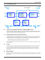
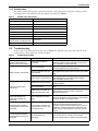
Transient Voltage Surge Suppression (TVSS) and EMI/RFI Filters
These UPS components provide surge protection and filter both electromagnetic interference (EMI)
and radio frequency interference (RFI). They minimize any surges or interference present in the
mains line and keep the sensitive equipment protected.
2.2
Rectifier/Power Factor Correction (PFC) Circuit
In normal operation, the rectifier/power factor correction (PFC) circuit converts mains AC power to
regulated DC power for use by the inverter while ensuring that the waveshape of the input current
used by the UPS is near ideal. Extracting this sinewave input current achieves two objectives:
• The mains power is used as efficiently as possible by the UPS.
• The amount of distortion reflected on the mains is reduced.
This results in cleaner power being available to other devices in the building not being protected by
the Liebert GXT3.
2.3
Inverter
In normal operation, the inverter utilizes the DC output of the power factor correction circuit and
inverts it into precise, regulated sinewave AC power. Upon a mains power failure, the inverter
receives its required energy from the battery through the DC-to-DC converter. In both modes of
operation, the UPS inverter is on-line and continuously generating clean, precise, regulated AC
output power.
2.4
Battery Charger
The battery charger utilizes energy from the mains power and precisely regulates it to continuously
float charge the batteries. The batteries are being charged whenever the Liebert GXT3 is connected to
mains power.
5