1
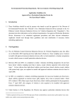
Installation and configuration manual 67R-01 6376 110R-00 6377 (the manual is also accessible via diagnostic software or www.ac.com.pl) ver. 1.2B 2014-10-21 Contents 1. 2. About AC SA .......................................................................................................................................... 3 Description of STAG DIESEL LPG fueling system .............................................................................. 4 2.1. Wyposażenie warsztatu montującego instalację STAG DIESEL ........................................................................ 4 2.2. List of applicable standards and regulations ........................................................................................................ 7 2.3. Wiring diagram for STAG DIESEL controller ....................................................................................................... 8 2.4. Installation of components ................................................................................................................................... 9 2.4.1. Filling valves ................................................................................................................................................ 9 2.4.2. LPG tanks .................................................................................................................................................... 9 2.4.3. Installation of the reducer ........................................................................................................................... 10 2.4.4. Installation of the pressure and temperature sensor PS-02 ...................................................................... 11 2.4.5. Installation of the knock sensor (engine vibration sensor) ......................................................................... 11 2.4.6. Installation of the exhaust temperature sensor .......................................................................................... 12 2.4.7. Wide-band oxygen sensor ......................................................................................................................... 12 2.4.8. Installation of the fuel rail pressure sensor ................................................................................................ 13 2.4.9. Installation of injection nozzles and manifold absolute pressure nozzles.................................................. 14 2.4.10. Installation of the LED switch ..................................................................................................................... 15 2.5. Identification of vehicles ..................................................................................................................................... 16 2.5.1. Guidelines for the identification marking .................................................................................................... 16 3. 2.6. Qualification of a vehicle for installation of an LPG system ............................................................................... 17 2.7. First start of the gas injection system................................................................................................................. 17 2.8. Installation quality inspection ............................................................................................................................. 17 AC STAG diagnostic software ............................................................................................................ 18 3.1. Description of the diagnostic software ............................................................................................................... 18 3.1.1. Connecting the controller to a PC computer .............................................................................................. 18 3.1.2. Software version ........................................................................................................................................ 18 3.1.3. Main menu ................................................................................................................................................. 19 3.1.4. Controller's parameters .............................................................................................................................. 23 3.1.5. Maps .......................................................................................................................................................... 27 3.1.6. Auto-calibration .......................................................................................................................................... 29 3.1.7. Errors ......................................................................................................................................................... 30 3.1.8. Recorder ................................................................................................................................................... 30 3.1.9. “Monitor” window ........................................................................................................................................ 32 3.1.10. “Oscilloscope” window ............................................................................................................................... 33 3.1.11. Gas level indicator...................................................................................................................................... 34 3.1.12. Controller’s update ..................................................................................................................................... 35 3.1.13. Programming the controller ........................................................................................................................ 36 4. 5. Sound signals ...................................................................................................................................... 39 Technical specification........................................................................................................................ 39 2 1. About AC SA AC SA is a Polish leader and also an important world’s manufacturer of automotive LPG/CNG systems under STAG brand. AC SA has been operating on the Polish automotive market for more than 25 years and currently it is the largest company in the segment of gas installations in Poland with over 400 employees. According to its own estimates, AC SA has more than 50% share in the Polish market. The products offered by AC SA are delivered to more than 30 countries all over the world and include more than 200 autogas products, of which controllers for LPG/CNG systems make the largest part. In 2011, the sales to foreign customers represented 63% of the total income of AC SA. The key foreign clients of AC SA include: Germany, Russia, Ukraine, Turkey and Thailand. 3 2. Description of STAG DIESEL LPG fueling system STAG DIESEL is a system designed for controlling autogas supply in Diesel engines. The system is based on typical components, e.g. tanks with auxiliaries, autogas piping, LPG injectors and reducers. The system pre-treats the fuel upstream the intake collector through evaporation and pressure stabilization depending on reducer adjustment. Pressurized LPG in a vapor phase is supplied to LPG injectors mounted on the engine and injected into the manifold through piping. The injectors are commanded with electric signals generated by the LPG controller. 2.1. Workshop equipment required for installation STAG DIESEL In accordance with the Regulation of the Minister of Infrastructure, any workshop undertaking to install autogas systems must have the following equipment: - multi-component exhaust analyzer; - electronic system tightness tester; - smokemeter with a valid certificate – for DIESEL systems; The mentioned devices should be available in the workshop (purchase confirmed with a receipt – invoice). The devices should meet the technical requirements set for diagnostic stations, i.e.: valid certification for the exhaust analyzer and declaration of compliance for the leak tester. Fitters installing autogas systems for DIESEL engines should have an available smokemeter with a valid certificate. Due to the obligatory analysis of exhaust fumes, AC SA requires testing performed with a smokemeter. Purchasing is an obligation, so renting a device or using services of an external company is allowed. 4 An exemplary list of necessary tools for installing DIESEL autogas systems is presented below: power-drill drill driver crimping pliers soldering tool Philips bit for drill-driver combination pliers nippers for cable cutting skinning pliers 2x plastic pliers for clamping coolant lines coolant line cutting nippers cutter hole saws: Ø51, Ø21 drilling bits: Ø2,2 mm, Ø2,5 mm, Ø5 mm, Ø6,5 mm, Ø8 mm, Ø14 mm metal cutting saw Philips screwdriver combination open-end wrenches: 8 mm,10 mm,13 mm,14 mm,17 mm, 19 mm socket wrenches: 4 mm,10 mm,12 mm,13 mm,19 mm Other materials: insulating tape tin self drilling screws fixing plates for autogas tubing plastic band clips thread sealant anticorrosion agent 5 Photo 1. Tools required for installation of autogas system in DIESEL engines 6 2.2. List of applicable standards and regulations Regulations related to the installation: 1. Regulation No. 115 by UN Economic Commission for Europe. 2. Regulation No. 67 by UN Economic Commission for Europe. 3. Other national regulations. 7 2.3. Wiring diagram for STAG DIESEL controller 8 2.4. Installation of components Prior to autogas conversion, the vehicle must be qualified for installation. Vehicles with defects related to the engines must be first repaired. Special attention should be adopted while inspecting the fuel system. Failure to observe these requirements may result in poor performance of LPG fueled engines due to reasons that are not related to the quality and methodology of installation. 2.4.1. Filling valves Photo 2. Installation of the filling valve in trucks Photo 3 . Installation of the filling valve in passenger cars Prior to autogas conversion, the vehicle must be qualified for installation. Vehicles with defects related to the engines must be first repaired. Special attention should be adopted while inspecting the fuel system. Failure to observe these requirements may result in poor performance of LPG fueled engines due to reasons that are not related to the quality and methodology of installation. 2.4.2. LPG tanks Photo 4. Installation of the gas tank in truck Photo 5. Installation of the gas tank in a minibus 9 Before mounting the tank, check strenght car chassis to which tank will be mounted. This is very important in case when in car is plastic floor-board of trunk. Tank should be protected by a shield when tank is installed under car chassis. Before checking electro-valves unplug gas ecu. Connecting outside voltage on electrovalves output can damage gas ecu. 2.4.2.1. Types of tanks - cylinder tanks: Cylinder tanks are fitted in a mounting rack secured with bolts. Stability is ensured by the use of racks and braces tested by the tank manufacturers. The tank should be positioned perpendicularly to the vehicle roll axis. Keep 10 cm spacing from the seats. If the tank is mounted in the boot separated from the back seat with a division panel and there is no risk of contact between the tank and the back seat, there is no need to keep the 10 cm distance. – toroidal tanks: Toroidal tanks should be attached to metal elements of the vehicle using parts supplied with the tank. Orifices must be cut out in the bodywork in order to enable routing of the gas tubes, ventilation of the gastight housing (inside of the torus) and fitting bolts. A plastic support should be placed underneath the tank. After tank installation, fit the gas tubes and wiring harness. All bolts and screws should be protected with anticorrosion coating. 2.4.3. Installation of the reducer The reducer is mounted on a support or directly on the element connected to the vehicle’s bodywork. Mount the reducer close to the engine in order to reduce the length of gas tubes between the reducer and injectors, in a location where it is not exposed to high temperatures. The reducer should be connected to the cooling system with metal tees integrated with the heater system. Selection of reducer output for Diesel fueled engines is not as strict as for petrol engines. For Diesel engines, reducer output can be twice as high as specified. 10 2.4.4. Installation of the pressure and temperature sensor PS-02 The PS-02 pressure sensor should be fitted on the gas tube between the vapor phase filter and gas injectors. 2.4.5. Installation of the knock sensor (engine vibration sensor) The knock sensor should be installed next to the engine in its factory-provided position (usually a threaded hole with 10 mm diameter in the engine block), if exists. If there is no factory provided fitting, position the sensor as close to engine width and height centerline crossing as possible. Examples of sensor positions have been presented on Figure 1. The sensor is provided with a mounting hole (dia. 8 mm). Ensure that the sensor is tightened with torque 20Nm (+-5 Nm), as this is a critical parameter for sensor performance. Sensor plug should be connected with a respective connector in the supplied harness and protected against contact with moving elements of the engine. Figure 1. Recommended positions of the knock sensor 11 2.4.6. Installation of the exhaust temperature sensor The exhaust temperature sensor is supplied with a sleeve to be welded to the exhaust manifold in a location providing representation for exhaust from all cylinders, possibly close to the engine head. Ensure that welding is tight. The sensor should be inserted to ¾ of the manifold diameter range and locked in the sleeve with thread. Correct positioning of the exhaust temperature in the exhaust system has been presented on Figure 2. (sensor thread – M10x1). Sensor outputs should be soldered to respective wires of the supplied harness and then insulated. Ensure that the sensor wire is not contacting hot elements of the exhaust manifold. Make sure that the sensor cable does not contact any hot surfaces of the exhaust manifold and the controller harness connection with the exhaust sensor wiring is positioned as close to the controller as possible. Cutting of the exhaust temperature sensor cable is not allowed. 2.4.7. Wide-band oxygen sensor In case when in car is mounted factory Wide-band oxygen sensor, wires from gas ecu should be solder like on wiring diagram. Wide-band oxygen sensor should be mounted in common place for all cylinders in exhaust manifold. Proper place of montage of wide-band oxygen in exhaust manifold is show on figure 2. If in exhaust manifold there isn’t any factory nut, extra nut with internal thread M18x1,5 should be welded. The horizontal position can cause condensation to drip onto the sensor, so we recommend at least 10 degrees from the horizontal. Proper montage of wide-band oxygen nut is show on figure 3. The lambda probe is not covered by the scope of supply of the Diesel autogas system. If there is no factory-installed probe, buy a separate lambda kit and fit it in the vehicle. Correct system calibration requires installation of the oxygen sensor. 12 Figure 2. Recommended positioning of the oxygen sensor (Lambda probe) and exhaust temperature sensor Figure 3. Minimum angle for oxygen sensor installation 2.4.8. Installation of the fuel rail pressure sensor Autogas systems for Diesel engines require connection of the fuel rail pressure sensor. Soldered connections should be made according to the diagram. Applies to engines fueled via Common Rail only. If two high pressure sensors are used, connect them according to the diagram, keeping the required order of sensor connections. Incorrect connection order will result in system functional errors Photo 6. Injection rail pressure sensor 13 2.4.9. Installation of injection nozzles and manifold absolute pressure nozzles Photo 8 Positioning of the common nozzles after the turbine Photo 7. Position of nozzles in the manifold (outside view) Installation of gas nozzles requires removal of the inlet manifold. Manifold removal provides access to inlet ducts that deliver air to individual cylinders. Drill nozzle holes in the manifold to allow insertion of nozzles to individual cylinders. If any of the cylinders is connected to more than one inlet duct, the nozzles should be placed in the same duct for all cylinders. Make sure that the nozzles are as close to respective valves as possible, at equal distance from and equal angle to the valves. The length of gas lines between the injectors and the nozzles should be equal for all cylinders. The nozzles should be secured against unscrewing. Connect injection tubes to the nozzles and protect them with metal clamps. Injectors should be attached to brackets and connected to injection lines. Next, install the supply line and pressure control line. Connect the harness to the injectors with order presented on the diagram. The size (diameter) of injection nozzles is 1,5 mm. Larger diameters should be used only if gas injectors are set on the map over 20 ms. The manifold absolute pressure nozzle should be installed in the common part of the inlet manifold (downstream the turbine). Photo 9. MAP nozzle installed in the inlet manifold 14 2.4.10. Installation of the LED switch The switchboard should be installed in a location visible to the driver. Additionally, the switchboard must be easily accessible and its operation must not interfere with driving. A connection with a pair of 3-pin connectors has been used to make it easier to connect the switch and STAG DIESEL harness. After installation, place the wires in a dedicated connector (supplied with the kit), while observing the correct connection order. The switchboard must be connected to the harness in the passenger’s compartment. 2.4.10.1. Operation of the LED switchboard and sound signals (user's manual) LED-401 switchboard features the following elements: LED circle – four LEDs in the form of a circle, which indicate the current LPG level in the tank. Four green LEDs indicate a full tank. Button with AC logo – enables fuel switchover and indicates the current mode of operation: • OFF – the vehicle is running on Diesel oil. • Flashes slowly (once per second) – the engine is running on Diesel oil, once the set parameters have been achieved, the system will automatically switchover to LPG • Flashes normally (twice per second) with no sound signals – the system is switching over to LPG; this can last up to 10 seconds depending on the current parameters of the engine. • Flashes rapidly (4 times per second) and emits sound signals – controller’s error (e.g. shutdown due to an empty LPG tank) • backlit in white – the vehicle is running on LPG • backlit in red – the vehicle is running on LPG, but the LPG tank is almost empty The following additional functionalities are accessible, when LED-401 switchboard is connected to STAG DIESEL controller: • LED brightness level adjustment (4 LED brightness levels to choose from) – for deactivated option of automatic control of LED illumination • LED switchboard buzzer volume control • LED switchboard orientation adjustment in order to ensure correct visualization of the LPG level indication, the buzzer installation location being the reference point • Automatic identification of the type of connected LED switchboard; a connected LED-401 switchboard is recognized by the application as LED-401 15 Figure 4. LED-401 set-up window The controller remembers the most recent fuel settings applicable prior to cutting off the supply voltage with the key (only after successful auto-adaptation „with firmware v1.4”). 2.5. Identification of vehicles M2 cat. vehicles (used for the carriage of passengers, comprising more than eight seats in addition to the driver's seat, and having a maximum mass not exceeding five tones) and M3 cat. vehicles (used for the carriage of passengers, comprising more than eight seats in addition to the driver's seat, and having a maximum mass exceeding five tones) should be marked by placing a label with the wording “LPG” on the bodywork. The markings should be made as stickers placed in front, on the back and on the internal side of the left door for right-side steering and right door for left-side steering. 2.5.1. Guidelines for the identification marking The identification marking is a weather-resistant stick label. Requirements for label colors and dimensions: Colors: Background: Border: Letters: green white or reflective white white or reflective white 16 Dimensions: Border width: Character height: Character thickness: Label width: Label height: 4 ÷ 6 mm ≥ 25 mm ≥ 4 mm 110 ÷ 150 mm 80 ÷ 110 mm The “LPG” wording should be positioned in the label center. Figure 5. LPG identification marking 2.6. Qualification of a vehicle for installation of an LPG system Perform technical inspection of the engine. If engine component wearing or defects are reported, make necessary repairs to make it fully operational with Diesel oil fueling 2.7. First start of the gas injection system Fill the tank with autogas and verify system tightness. Inspect connections of the LPG controller. Perform auto-calibration and adjustment while driving. 2.8. Installation quality inspection Verification of system completeness. Verification of tightness Functional test 17 3. AC STAG diagnostic software 3.1. Description of the diagnostic software 3.1.1. Connecting the controller to a PC computer After installation, connect a computer with AC STAG to STAG DIESEL controller using our RS, USB or Bluetooth interface. Before the software is launched, turn the key to supply voltage to the “switched ignition” circuit and activate the controller to enable communication. Once the software has been launched, AC STAG application will make an automatic communication attempt through the serial COM port connected to the interface. A status window in the left-and bottom corner confirms successful communication. Figure 6. Autosearch window Select another port from the Port menu in the top section of the screen if “No LPG controller found” message pops up. Figure 7. “No LPG controller found” warning 3.1.2. Software version AC STAG version information is displayed on the top bar. Figure 8 Indicates version 0.12.33 Figure 8. Main menu tabs 18 3.1.3. Main menu Options of the main menu: Port – changing communication port, connection to and disconnection from the controller, activation of automatic device detection. Figure 9. Menu “Port” Window – selection of the main windows. Figure 10. “Window” tab in the Menu The Window menu is used to restore the main windows if they have been closed. Application windows can be arranged as needed. For relocating windows use the “drag & drop” method. Press and hold the left mouse button over the bar of a selected window to move it. Release the button to embed or extract the window in the current mouse pointer position. Language – selection of the language version; language change will cause AC STAG restart. Tools – updating the controller and LED switchboard, automatic distribution of setting windows, restoring defaults Update of the controller and LED switchboard is discussed in section 3.1.12 In order to save the controller settings and maps select Tools → Save settings in the main menu (see Figure 11). 19 Figure 11. “Tools” tab in the Menu Indicate the location on the computer’s hard drive where the file with the setting is to be saved, enter the name of the file and click Save. The procedure is used for user’s settings and maps. In order to load the controller settings and maps select Tools → Load settings in the main menu (see Figure 11). The application will ask for indication of the file with settings (*.set extension). Browse for the file to display the Open saved parameters window. The user can open settings only, map only or settings with maps. Check the desired configuration in the below window and confirm with Ok (see Figure 12). Figure 12. “Open saved parameters” window 20 o Help – information about the application and controller. Figure 13. “Gas controller info” window Parameters of the “Gas controller info” window: o Diesel oil – total controller operation time on Diesel oil displayed in the following format: H – hours, M – minutes, % - percentage share in the total operation time. o Since last connection – time of operation on Diesel oil from the last connection to a PC. o o o Gas extra-injection – total controller’s operation time with autogas post-injection. Since last connection – time of operation with LPG fumigation from the last connection to a PC Service – the set time of inspection. When the counter of working hours of the controller in an active gas extra-injection mode reaches the scheduled service setting, the controller will generate a sound upon each shutdown of the switch to remind the user about the required system check. 21 The method for setting the time to system’s inspection has been described in the following section. A negative value denotes the time, which has passed from the first indication of the need to carry out the inspection. To set the time to inspection, click on the button in the window Gas controller info; the following window will be displayed. Figure 14. “Service set” window The desired time to inspection is calculated based on the selected mileage, after which the inspection is to be carried out. A default conversion rate of 1h – 50 km is used with calculating the time to inspection value; yet, the value of the conversion rate can be modified. In the above-mentioned window, an inspection after 10,000 km [1 km = 0.62 mile] has been selected, which in this particular case translates into 200 hours of operation. Select “Inactive” in the selection field, in order to delete the inspection. Once the above-mentioned option has been selected, the controller will not check the time to inspection any more. The section below the time of operation values in the window Gas controller info includes the following events recorded by the controller: o o o o o o First PC connection – the date, on which the controller was connected to a PC with the diagnostic software for the first time. First change of settings – the first modification of the controller’s settings. Last PC connection – the date, on which the controller was connected to PC with the diagnostic software for the last time. Mod. date 1 ÷ Mod. date 5 – the list of modifications in terms of controller’s settings. From the most recent ones to the earliest ones. Clear errors – a recorded event from the most recent deletion of errors of the gas controller. Unknown change of settings – the event is displayed, if controller’s settings are modified with a date preceding the date of the most recent modification. A code is assigned to each event, which identifies the PC, which was used to modify the settings. With the modification date as well as the code, which identifies the PC, which was used to introduce the change, the user can determine whether or not the controller’s settings were modified by third parties. The following additional information can be found in the bottom section of the window: o o ECU S/N. Your PC code – the code assigned to the PC, on which AC STAG diagnostic software is currently running. 22 3.1.4. Controller's parameters At the bottom of the screen, the software displays the controller’s firmware version, its model as well as the date and time of compilation of the firmware: STAG Diesel-4 –controller’s model ver. 1.3 –controller’s firmware version number 20.0.0 – controller’s version number 2011-08-07 12:21:00 – date and time of compilation of the controller’s firmware Parameters group has been divided into subgroups, which allow the user to set parameters individually for each vehicle. Additionally, the user can freely arrange the parameters' windows by dragging with the left mouse button and dropping in the desired location. The user can also collapse the windows Figure 15. “Parameters” → “Car parameters”. Vehicle parameters: Number of cylinders – the number of cylinders or the number of gas injectors installed in the vehicle. RPM signal source – type of sensor sending the RPM signal to the gas controller. RPM signal – default 2,5V should be changed only if rpm reading is incorrect (after correct setting of pulses per rotation). Number of pulses per rotation – the value should be adjusted to make the reading of rpm in the application correspond to the dashboard indications. RPM signal filter – enabling RPM signal filtering if reading problems occur. Injector type – type of injector in the Diesel engine fueling system. If the signal from Diesel oil injector is used, the gas controller automatically verifies injector type and sets the parameter after autocalibration. 23 Figure 16. “Parameters” → “Gas controller settings” Gas controller settings ◦ Calibration parameters: Working pressure – gas pressure saved during auto-calibration. Min. pressure – gas pressure value, below which the controller switches to Diesel oil. ▪ Min. CR pressure – common rail pressure saved during auto-calibration. ▪ Gas temperature – gas temperature saved during auto-calibration. ▪ Injection time measurement threshold. – This value is set and saved during auto-calibration. Value set by auto-calibration should be changed only in case wrong reading of “Diesel oil dose ON”. Value of “Diesel oil dose ON” is lower than 0,3ms or unstable. In first place before changing value of "Injection time measurement threshold" check correctness of reading rpm signal. 24 ◦ Enabling gas extra-injection: Fuel type – type of fuel for the engine during operation of the gas controller Switch-over threshold – engine rpm threshold value required for the controller to switch to LPG. Switch-over time – time after starting the engine, when the controller can switch to LPG. Reducer filling delay – the time between activation of the LPG/CNG solenoid valve and activation of the gas injectors. Switch-over temp. – reducer temperature required for the controller to switch to LPG. ◦ Switch-over to Diesel oil: Min. gas RPM – engine rpm threshold value, below which the controller switches to Diesel oil. Max. gas RPM – engine rpm threshold value, above which the controller switches to Diesel oil. Pressure error delay – time, after which the controller switches to Diesel oil, if the gas pressure value is lower than the minimum value set in the calibration parameters. Min. gas temp. – minimum gas temperature, below which the controller switches to Diesel oil. Max. exhaust temp. - maximum temperature of exhaust over which switching to Diesel oil occurs. Max. engine knocking - maximum level of knock sensor reading over which switching to Diesel oil occurs. ◦ Sensors and actuators: Gas injector type – settings of the installed gas injector Gas level indicator – allows access to the parameters of LED – 401 switch Oxygen sensor type – setting of the applied Lambda sensor type. - Factory-fitted – wide-band current probe fitted by the factory. - External – wide-band current probe installed with the autogas system, dedicated for Diesel engines. Selection of the External option for the installed original probe may result in probe damage. Figure 17. Tab “Parameters” → “Advanced settings” 25 Advanced settings: Type of map – input parameter for setting the gas extra-injection map. Set the gas map to MAP pressure read from PS-02 sensor, Diesel oil dose read from the Diesel injector signal or from the accelerator position sensor. Diesel oil reduction – enabling or disabling the algorithm for Diesel oil fueling reduction. Min. Diesel oil ratio – minimum proportion of Diesel oil in the fuel, below which the gas controller will not continue to decrease its dose. Adaptation mode – (additional information on adaptation modes can be found in a further part of the manual) - Automatic – after collection of data about engine parameters while running on Diesel oil (as described below) and (manual) switchover to autogas, the gas controller will automatically adjust the amount of LPG fuel and gradually decrease the amount of Diesel oil. The results will be saved on the maps displayed in the “Maps” tab in real time. The fine-tuning process will be completed when all ranges of engine operation are adjusted. - Semi-automatic - after collection of data about engine parameters while running on Diesel oil (as described below) and (manual) switchover to autogas, the user can manually change gas injection volume in different engine operation ranges, while the gas controller will automatically reduce the amount of Diesel oil to keep the same conditions of engine operation as in Diesel oil fuelling mode. - Manual – the user can manually change both gas injection and Diesel oil reduction for each engine operating range. Gas injector type – settings of the installed gas injector: - Sequence – the gas controller manages the injectors in accordance with engine cycle; supply of autogas to injectors, near the suction valves, is required. - Standard – the gas controller can correctly manage fewer injectors than cylinders; it is required to supply gas through injectors to the common section of engine inlet manifold, away from the suction valves to allow proper mixing of gas with the sucked air. Press button next to the “Injection type” field to display the “Injection sequence” window: Figure 18. “Injection sequence” window 26 The window is used for switching the order of gas injections to individual cylinders. Default value corresponds to the standard order of injectors for an in-line engine with a given number of cylinders. Set the order of cylinders starting from the one adjacent to the timing gear. Vehicle data: The tab allows the fitter to save the most important data about the vehicle and system parameters. Figure 19. Tab “Parameters” → “Vehicle information” 3.1.5. Maps This window includes 3D maps of the gas controller. Engine rpm value is displayed on the vertical axis. The displayed rpm values can be modified by clicking on the desired value with the left mouse button and entering a new value. Diesel oil doses are displayed along the horizontal axis. Injection times can be modified by clicking on them with the left mouse button and entering new values. Additionally, rpm and dose values displayed along the axes can be modified by the following key combinations: „CTRL” + „ALT” or „SHIFT” with „←”, „→”, „↑”, „↓”. The values shown on the map are color-coded according to value range. Additionally, the map contains information about engine performance (lighter areas around correct mapping points). Similarly, areas without mapping completed are darker (see Figure 35 in section 3.1.13). New columns and lines are added by clicking the right mouse button on the map while holding “CTRL”. The multiplier can be modified by highlighting with the left mouse button and pressing the ENTER key. Modification is introduced via the following key combinations: “CTRL” and “↑” or “↓” and “+”, ”-“. In the event the “Shift” key is pressed and held and the above-mentioned combination is used, the multiplier will be 27 changed incrementally (step change). Pressing the space-bar results in highlighting the point closest to the engine operation point. By pressing and holding the space-bar while driving, one can easily correct the multiplier value at the intersection of the closest Diesel oil dose and the engine rpm value. What is more, columns and lines can be deleted. It is also possible to highlight a larger area for edition. Press simultaneously “Shift” + “Delete” to delete lines and "Alt" + "Delete", also simultaneously, to delete columns. Highlight the desired points prior to any deletion operation. Gas injection time map (marked as “gas”) Figure 20. Gas injection time map This map allows adjustment of the basic gas injection pulse depending on load (x axis) and engine rpm (y axis). Engine load is represented by the current dose of Diesel oil. The map allows adjustment of basic gas injection pulse with accuracy of 0.1 ms. The actual gas injection pulse displayed in the “Monitor” window will be corrected by gas injector opening and closing times, as well as gas temperature and pressure. Diesel oil reduction map Figure 21. Diesel oil reduction time This map allows adjustment of Diesel oil reduction rate depending on load (x axis) and engine rpm (y axis). Engine load is represented by the current dose of Diesel oil. The map allows selection of voltage, by which the CR pressure signal will be reduced with accuracy of 0.01V. If Diesel oil reduction is deactivated in Parameters → Advanced settings, the map will be ignored by the gas controller. 28 Temperature correction view Figure 22. Gas temperature correction The temperature correction tab enables one to set the dose correction depending on the gas temperature. The correction is applied by highlighting a given spot with the left mouse button and setting the desired correction value by pressing “↑” or “↓”. Use the right mouse button to increase the number of spots by clicking in the desired location. 3.1.6. Auto-calibration After correct installation of mechanical components and adjustment of controller settings in the “Parameters”, start and warm up the engine, reducer temperature must be 50°C. When the operating temperature is reached, launch the auto-calibration procedure. Auto-calibration is an automatic procedure to map engine parameters at idle speed. The automatic process does not require operator action. The system confirms successful or unsuccessful completion. If the procedure is unsuccessful, follow the displayed messages and restart the process. After successful auto-calibration, gas fumigation will be activated automatically upon each engine start. Figure 23. Auto-calibration window 29 3.1.7. Errors “Errors” tab informs the user about errors of the STAG DIESEL controller. It is possible to read and delete errors. Figure 24. “Errors” tab 3.1.8. Recorder “Recorder” window enables the user to browse through the files of the STAG parameters logger, which was fitted in the vehicle and connected to the diagnostic connection of the STAG controller. Connecting AC STAG software with the LPG controller is not required in order to browse the logger files. Once the logger has been connected to a PC using an USB interface, it is automatically detected and the recorded files are displayed in the window. The logger window will display the following message “Status: Recorder available”. The logger’s firmware version as well as the current date will be displayed too. From this moment on, the user can view the logger’s files. Figure 25. Recorded files 30 Double click with the left mouse button on a given file to load it or use the "Open" button. In the event a file with a set marker is loaded (Figure 25), an oscilloscope file will be displayed with the cursor set on the event. This means that the user pressed the logger button while the vehicle's engine was working. The monitor window will display the recorded parameters. Figure 26. “Recorder” tab Click on "Clear" button in order to delete the logger's files. The time needed to perform the above-mentioned operation may be substantial as it depends on the number of recorded files. 31 3.1.9. “Monitor” window Monitor window displays current system's parameters: LED switchboard with the switch – click on the switchboard to switch between LPG and Diesel oil. Pressure [bar] – LPG pressure and pressure in the MAP inlet manifold and Diesel oil pressure in the injection rail. Diesel oil dose ON [ms] – calculated Diesel oil dose per engine cycle. Gas Inj. dose [ms] – injection time for the LPG injectors. Temperature [ºC] – temperature of the injected gas, reducer temperature, temperature inside the controller, exhaust temperature. Voltage [V] – voltage values for accelerator position, knock sensor, common rail sensor, % of oxygen in exhaust gas and battery voltage. Speed [rpm] – engine rpm value Figure 27. Monitor window All the parameters displayed in the monitor window, are also visible on the oscilloscope. A particular signal can be switched off in order for the oscilloscope not to record it. To do so, uncheck a given signal in the window by the name. Click on the name field of a given parameter displayed in the monitor window to enable its color change. The user can adjust the number of displayed parameters by clicking category bar, which collapses the parameters. button or clicking on the parameter Use Gas dose window to deactivate individual gas injectors by clicking on a respective icon. The operation is helpful for diagnosing mechanical damage of the injector. Please note that for sequential systems this may result in irregular operation or event engine damage! Deactivation of individual gas injectors does not impact Diesel oil reduction. The exception from this rule is deactivation of all gas injectors, which causes deactivation of Diesel oil reduction until any of the gas injectors is reactivated. Particularly for sequential systems, ensure that all injectors are reactivated after troubleshooting and repairs are completed. 32 Figure 28. “Gas Inj. Dose” window What is more, Monitor window offers the auto-hide option, which can be activated by clicking on the symbol . A hidden window will be displayed as a bar only. A hidden window automatically drops down, if the mouse cursor is pointed on its bar. 3.1.10. “Oscilloscope” window To make “Oscilloscope” window visible, select Window → Oscilloscope from the main menu. Figure 29. Oscilloscope “Oscilloscope” window displays all the signals visible in the "Monitor" window. All the control buttons have the following functions, starting from the left-hand side: Start the oscilloscope Stop the oscilloscope Record the current oscilloscope Load the oscilloscope from a file saved on the hard drive Reduce chart scale Increase chart scale File information By pointing the cursor to a given event, while viewing the oscilloscope files, the user can view the values underneath the cursor in the Monitor window. The user can move the oscilloscope with the slide control at the bottom of the screen or by pointing the cursor to the edge of the diagram and holding the left mouse button. 33 Press button to display a window with information on the loaded file related to the number of registered samples and recording time, as well as versions of the application and controller used for sampling Figure 30. “File info” window 3.1.11. Gas level indicator Click the right mouse button on the switchboard in order to edit settings of the Gas level indicator. A setting window will be displayed, which enables selection of threshold voltage values for the indicator. Figure 31. “Gas level indicator” window 34 The window enables access to the following settings: Gas level sensor type – the user can select from among the following LPG level sensors: WPGH Hall sensor (3-wire), 50 [kOhm], 90 [Ohm] resistance sensors (2-wire). Characteristics WPG – sensor signal increment method: decreasing or increasing. Sound level – buzzer volume, 4 levels. LED brightness level – LED brightness setting for the level indication (setting unavailable for activated option of “Automatic illumination control”). Buzzer position – once LED400 has been installed, the user must select the location of the speaker, to ensure correct visualization of the LPG level indication. Automatic illumination control – parameter to control switching of automatic diode illumination in the LED switchboard depending on illumination intensity (for “Inactive” selection, it is possible to set the intensity of LED illumination by specific values of “LED brightness”). The voltage boxes can be edited in order to ensure correct level indication. Once the sensor type has been selected, set the extreme values for en empty and a full tank, by setting the voltage values, including a margin, to ensure correct indication for the “Empty” and “Full” reading. Enter intermediate values, in appropriate proportions, in both of the middle boxes. 3.1.12. Controller’s update Turn the key in the ignition in order to supply the controller and enable update of the controller’s firmware. Select Tools → Devices update in the main menu. Figure 32. “Tools” tab in the main menu A window (Figure 33) indicating the current version of the controller's firmware as well as the available updates will be displayed. Parameters window includes a list of devices, for which an update is available. Firmware updates for STAG Diesel, LED switchboard and recorder are available. Select the controller (e.g. STAG Diesel-4) or LED switchboard (LED-400) in Devices parameters window, to proceed with the firmware update. Connect the logger and use Find Recorder button in order to update the firmware of the Stag Parameter Logger. Subsequently, select the desired firmware version from Available updates window. In the event the list of available updates is not displayed, click on Load Update button and select the desired file from the computer's hard drive. Having selected the desired firmware version, click on Update button. Wait until the update process has been completed. The update process progress is reflected by the progress bar. The engine must be turned off during the update. 35 Figure 33. “Devices update” window 3.1.13. Programming the controller When system components have been properly installed, proceed with controller calibration. The first stage is to set the parameters described in part 3 of this manual. After all parameters are set and the auto-calibration is completed, map engine operating parameters on Diesel oil. Start and warm up the engine. When the operating temperature is reached, make sure the Lambda value in the “Monitor” window is not zero, which confirms sensor warm-up and correct operation. When all the conditions are met, perform a drive test for calibration on Diesel oil (switchboard LED’s should not be lit or flashing). The test drive should include step changes of engine load and rpm, while checking the map of collected data points shown in the “Maps” tab (Figure 35). After mapping of all engine operating ranges, adjust autogas dosing and Diesel oil reduction rate. It is helpful to use dedicated indicators in Window → Indicators menu 36 Figure 34. “Indicators” menu Oxygen sensor deviation – mixture ratio difference between the current value for LPG and Diesel oil value for the same point. Positive value indicates that the mixture is too rich compared to Diesel oil; negative value – too lean. Diesel oil ratio – current Diesel ratio in the mixture. Diesel oil reduction limit – red color means no further Diesel oil reduction option for a given performance point (as a result of reaching the “Diesel oil ratio” value set in the “Minimum Diesel oil ratio” field or CR pressure drop below the value set in the “Min. CR pressure” field. Knocking – red color indicates abnormal combustion (probably as a result of gas dose that is too high or Diesel oil reduction that is too high). It is necessary to reduce gas injection rate for this performance point due to the risk of damaging the engine!!! After gas injection pulse reduction check the mixture for that point (see “Oxygen sensor deviation” indication) and correct the Diesel oil reduction map as needed. Calibration during test drive can be performed in three ways: Automatic mode (recommended) – after switch-over to gas, perform a test drive under conditions that are as close to the calibration conditions as possible. The controller will automatically adjust the gas dose and gradually reduce Diesel oil ratio with results presented in real time on maps in the “Map” tab. The fine-tuning process will be completed when all required ranges of engine performance are adjusted. (Probably, the drive should last longer than the calibrating test drive.) Adjustment of individual points is confirmed by bold values of injection pulse and Diesel oil reduction for a given point (see Figure 35). The point is fine-tuned when: current “Diesel oil ratio” reaches the value entered in the “Min. Diesel oil ratio” field, or, abnormal combustion is detected (in such case, gas injection pulse will be automatically reduced to a safe level). Semi-automatic mode – after switch-over to gas, perform a test drive under conditions that are as close to the calibration conditions as possible. The user must enter individual gas injection pulse values manually for points of current engine performance (this is why it is not recommended to 37 perform the procedure in this mode only by one person) and the controller will automatically reduce Diesel oil ratio with results presented in real time on the “Diesel oil reduction” map in the “Maps” tab. For selection of injection pulse values, it is helpful to use indicators in “Window” → „Indicators” menu, particularly “Diesel oil reduction limit” and “Knocking”. Activation of any of these indicators alerts if it is necessary to reduce injection pulse in a given point. If none of the indicator is active, the user can increase the value of gas injection pulse up to the required level of “Diesel oil ratio” in a given point. Adjustment of Diesel oil reduction in a given point is confirmed with bold value of Diesel oil reduction (Figure 36). The user should start adjusting another point only if the current point adjustment is completed (see above). Adjustment is completed when all ranges of engine performance are finetuned. (Probably, the drive should last longer than the calibrating test drive.) Manual mode – after switch-over to gas, perform a test drive under conditions that are as close to the calibration conditions as possible. The user must enter the values for gas injection pulse and Diesel oil reduction manually. For selection of values, it is helpful to use indicators in “Window” → „Indicators” menu. The following rules must be followed while adjusting gas injection pulse and Diesel oil reduction: keep the oxygen sensor deviation value close to zero, active “Knocking” indicator informs that it is necessary to reduce the gas injection pulse in a given point (and check the oxygen sensor deviation to correct map point’s Diesel oil reduction as needed), active “Diesel oil reduction limit” indicator informs that it is necessary to reduce the Diesel oil reduction value in a given point (and check the oxygen sensor deviation to correct map point’s injection time as needed), if the “Diesel oil reduction limit” and “Knocking” indicators are inactive, the user can increase gas injection pulse and Diesel oil reduction values (while keeping the “Oxygen sensor deviation” close to zero) until the required ratio of Diesel oil in the mixture is reached. Figure 35. Range 2x2 points have been mapped Figure 36. Range 2x2 points have been correctly tuned 38 4. Sound signals The controller emits the following sound signals: three sound signals – a switchover to Diesel oil due to insufficient LPG volume in the tank three short sound signals and one long signal – a controller’s error after turning off the ignition two short signals and one long signal after switching the ignition off – required system inspection missing. Go to a service station in order to inspect the system. 5. Technical specification 12[V] (-20% ÷ +30%) Supply voltage Maximum current draw of the controller (1 ohm LPG injectors) 25 [A] Current consumed when in sleep mode < 10 [mA] -40 - 125 [°C] Operating temperature Protection class IP54 39