1
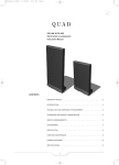
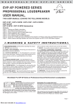
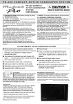
WPM-1
OPERATING MANUAL AND USER GUIDE
www.wharfedalepro.com
WPM-1 User Manual.indd
1
2011-1-24
10:29:25
OPERATING MANUAL AND USER GUIDE
IMPORTANT WARNINGS & SAFETY INSTRUCTIONS
1.
Read these instructions
2.
Follow all instructions
3.
Keep these instructions
4.
Do not block any ventilation openings. Install in accordance with the manufacturer’s
instructions.
5.
Do not install near any heat sources such as radiators, heat registers, stoves, or other
apparatus (including amplifiers) that produce heat.
6.
Do not defeat the safety purpose of the polarised or grounding plug. A polarised plug has two
blades with one wider than the other. A grounding plug has two blades and a third grounding
prong. The wide blade or the third prong is provided for your safety. If the provided plug does
not fit into your outlet, consult an electrician for replacement of the obsolete outlet.
7.
Protect the power cord from being walked on or pinched particularly at the plugs, convenience
receptacles, and at the point where they exit from the apparatus.
8.
Only use attachments/accessories specified by the manufacturer.
9.
Use only with a cart, stand, tripod, bracket, or table specified by the manufacturer, or sold with
the apparatus. When a cart or rack is used, use caution when moving the cart and apparatus
combination to avoid injury from tip-over.
10. Unplug the apparatus during lightning storms or when unused for long periods of time.
11. USE WITH AMPLIFIERS – In order to avoid damage to drivers and other equipment, it is
advisable to establish and follow a routine for powering up and powering down a sound system.
With all system components connected, turn on source equipment (mixers, signal processors,
record and playback units, etc.) BEFORE powering up amplifiers. Transient voltages from
powering up source equipment can damage speakers if amplifiers are already turned on.
Make sure that amplifier volumes are set to their minimum settings and power up any system
amplifiers LAST. It is recommended that all system components be allowed to stabilize for
several seconds before any source signals are introduced or level setting adjustments are
made. Similarly, when shutting systems down, turn all amplifiers off first, before powering down
any other system components.
12. CABLES – Do not use shielded or microphone cables for connection between amplifiers and
speakers. Use only approved speaker cables with proper connectors.
13. CAUTION – These professional loudspeaker systems are capable of generating very high
sound pressure levels. Use care with placement and operation to avoid exposure to excessive
volume levels. Permanent hearing damage can result when operated to extreme levels.
14. Refer all servicing to qualified personnel. Servicing is required when the apparatus has been
damaged in any way including but not limited to power supply cord or plug damage, liquid
ingress, foreign objects in the chassis, exposure to rain/moisture or impact damage. In addition
the unit must be serviced when you experience any abnormal operation.
WPM-1 User Manual.indd
1
2011-1-24
10:29:25
WPM-1
15. CAUTION: These servicing instructions are for use by qualified service personnel only. To
reduce the risk of electric shock, do not attempt to perform any servicing other than that
contained in the operating instructions unless you are qualified to do so. In addition opening the
casing will result in your warranty becoming null and void.
16. Do not install this apparatus in a confined space such as a book case or similar unit. Good
ventilation should be maintained around the apparatus and any vents, air-inlets or fans should
not be obstructed by objects such as paper, table-cloths, curtains etc.
17. WARNING: To reduce the risk of fire or electric shock, do not expose the apparatus to rain or
moisture. The apparatus should not be exposed to dripping or splashing and objects filled with
liquids, such as vases, should not be placed on the apparatus.
18. WARNING: To prevent injury, this apparatus must be securely attached to the boom arm in
accordance with the installation instruction.
19. WARNING: The mains plug/appliance coupler is used as a disconnect device, the disconnect
device shall remain readily operable.
ATTENTION: RISQUE DE CHOC ELECTRIQUE-NE PAS OUVRIR
20. This lightning flash with arrowhead symbol within an equilateral triangle is intended to alert the
user to the presence of non-insulated “dangerous voltage” within the product’s enclosure that
may be of sufficient magnitude to constitute a risk of electric shock.
WARNING! To reduce the risk of electric shock, do not remove the cover (or back) as there
are no user-serviceable parts inside. Refer servicing to qualified personnel.
The exclamation point within an equilateral triangle is intended to alert the user to the presence
of important operating and maintenance instructions in the literature accompanying the
appliance.
21.
(Protective earthing terminal) The apparatus should be connected to a mains socket outlet
with a protective earthing connection.
22.
Correct Disposal of this product. This marking indicates that this product should not be
disposed with other household wastes throughout the EU. To prevent possible harm to the
environment or human health from uncontrolled waste disposal, recycle it responsibly to
promote the sustainable reuse of material resources. To return your used device, please use
local return and collection systems or contact the retailer where the product was purchased.
They can take this product for safe environmentally friendly recycling.
WPM-1 User Manual.indd
2
2011-1-24
10:29:25
OPERATING MANUAL AND USER GUIDE
TABLE OF CONTENTS
Important Warnings & Safety Instructions.............................................. 1
Introduction / About the WPM-1............................................................... 4
Key Features / Contents........................................................................... 5
Setup........................................................................................................... 6
Microphone Stand Mounting Procedure................................................. 7
Wiring Diagrams........................................................................................ 9
Assembly Diagram.................................................................................. 11
Mounting Accessories............................................................................ 12
Specifications.......................................................................................... 13
Warranty................................................................................................... 14
WPM-1 User Manual.indd
3
2011-1-24
10:29:25
WPM-1
INTRODUCTION
Congratulations on the purchase of your WPM-1 personal monitoring system
The Wharfedale Pro WPM-1 is the result of many years experience in the use,
design and manufacture of professional audio products. We take great pride in
engineering and building every Wharfedale Pro product and wish to thank you
for entrusting us with your sound.
From the time that Gilbert Briggs built his first loudspeaker in 1932, to the
present day, Wharfedale have maintained the same standard of quality in
components, workmanship and performance.
Please take the time to read this manual completely in order to ensure that you
get the most from your WPM-1 personal monitoring system.
ABOUT THE WPM-1
The WPM-1 from Wharfedale Pro is a personal monitoring solution with a
number of great features that suit performers and artists that demand perfect
monitor mixes and total control. A 5” full range driver is matched to the onboard processing, EQ and amplification to provide clear, natural and intelligible
vocal foldback.
The WPM-1 can be stand mounted with straight or boom mic stands,
alternatively the WPM-1 can be placed on the stage itself for maximum
versatility. Front panel controls allow you to fine tune your onstage vocal sound
and the integration of your monitor mix. With a WPM-1 you no longer get the
monitor mix that your engineer supplies, you hear exactly what you want to
hear.
The WPM-1 also includes an instrument/line level input and mix output,
facilitating use as a small format personal mixer with 3 inputs. This versatile
interfacing allows the WPM-1 to fit into the widest range of on stage situations.
The WPM-1 uses the same high tech gas-assist injection moulding techniques
as used in our famous Titan Series loudspeakers, ensuring road tough
reliability and ultra light portability.
WPM-1 User Manual.indd
4
2011-1-24
10:29:25
OPERATING MANUAL AND USER GUIDE
KEY FEATURES
•
75W continuous power output
•
5” full range driver
•
Microphone, line/instrument and auxiliary inputs
•
Microphone thru, line and mix outputs
•
Vocal volume and EQ controls
•
Independent master and auxiliary level controls
•
Switchable output sensitivity
•
Ultra lightweight gas-assist injection moulded enclosure
•
Dual angle mic stand receptacles and microphone
mounting system
•
IEC receptacle for AC supply
•
1x WPM-1 active personal monitoring solution
•
1x Stand mount adapter
•
1x ⅜” Mic clip / boom arm mounting
•
1x ⅝” Mic clip / boom arm mounting
•
IEC AC power cable
CONTENTS
WPM-1 User Manual.indd
5
2011-1-24
10:29:25
WPM-1
SETUP
The WPM-1 can be used in many different ways to suit the widest range
of applications. It’s versatile shape and flexible input/output configurations
ensure that the WPM-1 can fit into any situation on stage.
The WPM-1 is effective when fed from a mixing console at larger venues
or when used as the overall front of house mixer at small shows. It can
be used as a floor based wedge monitor while it is equally at home when
mounted at the centre of a microphone stand.
Use the following points and diagrams to ensure you get the most out of
your WPM-1 in every possible configuration.
1.
Observe correct gain structure and calibrate all inputs and outputs.
Ensure all mic/line/instrument switching is correctly set, when
changing the settings or rewiring always check all inputs and
outputs.
Do not overload any inputs or outputs.
Be careful with EQ, less is more! Excessive EQ boost can dramatically reduce headroom and increase the risk of feedback.
2.
Ensure the WPM-1 is secure.
Only use heavy duty microphone stands that can withstand the
weight of the WPM-1 plus any other accessories including
microphones, clips, shockmounts and cables.
Check that the WPM-1 is well balanced and will not tip over.
Ensure that the correct mounting hardware is used for mounting
microphone stands.
WPM-1 User Manual.indd
6
2011-1-24
10:29:25
OPERATING MANUAL AND USER GUIDE
MICROPHONE STAND MOUNTING PROCEDURE
1.
Place an appropriate microphone stand on a stable and even surface.
Ensure that the stand will not cause an obstruction to the stage or
front of house area.
Ensure that the polar pickup pattern of the microphone is not within
the vertical or horizontal coverage of the front of house system.
Poorly positioned microphones will greatly increase the risk
of feedback.
2.
Attach the microphone stand adaptor to the threaded shaft on the stand. If you are using a boom stand remove the boom arm
and attach the adaptor to the top of the vertical section.The stand adaptor has a thread adaptor to cater for ⅜” and
⅝” sizes.
Observe the slot at the top of the adaptor, there is a ‘key’ within the
WPM-1 microphone stand receptacle that will fit into the slot. This system will lock the WPM-1 into place and will prevent it
from rotating during the performance. The performer will be
perpendicular to the slot.
Ensure that the adaptor is securely screwed to the microphone
stand.
3.
There are 2 adaptor receptacles, one on the angled section for use with a boom stand and one on the bottom that is for use with straight microphone stands.
Place the WPM-1 onto the stand adaptor. Take care to allow the
weight of the WPM-1 to gently rest on the stand adaptor. Before
you release the weight of the WPM-1 make sure that it feels secure
and well balanced on the stand.
4.
If you do not wish to mount a boom arm and microphone on the top of the WPM-1 the mounting process is complete and you are ready to make your wiring connections, jump to step 9.
5.
Screw the boom arm mounting into the base of your boom arm. ⅜” and ⅝” boom arm mountings are provided with your
WPM-1.
WPM-1 User Manual.indd
7
2011-1-24
10:29:25
WPM-1
6.
Remove the boom arm mount receptacle cover, keep this in a safe place should you need it again for a different application.
7.
Place the boom arm mounting into the receptacle on the top of
the WPM-1.
8.
Screw the mounting into place by spinning the middle section of the mounting hardware. You can loosen or tighten the top section to adjust the microphone angle or tightness.
9.
Attach all wiring starting with the audio connections.
The connectivity will depend on the application.
Once all audio connections are complete you are ready to connect
the AC supply, always ensure that the power switch is in the
off position and that all connected output devices are muted or have
gain/volume controls set to minimum.
Ensure that all wiring is neat and safe, take care to avoid creating
tripping hazards. Adequate length wires should be used to
avoid potential damage to connected equipment.
When mounting a WPM-1 take steps to ensure that all elements are
stable and safe at every step of the setup procedure. If any element feels
unbalanced or unsafe revert back to the previous step and ensure that all
connections are secure. Ensure that all mounting hardware is appropriate
and capable. Incorrect mounting of this product can cause serious injury
and damage to property.
WPM-1 User Manual.indd
8
2011-1-24
10:29:25
OPERATING MANUAL AND USER GUIDE
WIRING DIAGRAM FOR USE WITH A MIXER
To Line Input
M i c Th r u to
Mic input on
FOH Mixer
To Mic Input
Foldback Mix
To PA
WPM-1 User Manual.indd
9
2011-1-24
10:29:46
WPM-1
WIRING DIAGRAM FOR USE AS A MIXER
To Mic Input
To Inst Input
To PA
10
WPM-1 User Manual.indd
10
2011-1-24
10:30:09
OPERATING MANUAL AND USER GUIDE
ASSEMBLY DIAGRAM
11
WPM-1 User Manual.indd
11
2011-1-24
10:30:10
WPM-1
STAND ADAPTOR
Main Section
Thread Adaptor
⅝" BOOM ARM MOUNT ADAPTOR
⅜" BOOM ARM MOUNT ADAPTOR
12
WPM-1 User Manual.indd
12
2011-1-24
10:30:11
OPERATING MANUAL AND USER GUIDE
SPECIFICATIONS
System Type
Frequency Response @ +/- 3dB
Peak SPL
Power Handling
Continuous
Music
Driver
Driver Size
Frame Material
Input Sensitivity
Mic input
Line and Aux input
Mic EQ
Enclosure
Dimensions
(L)
(W)
(H)
Enclosure Type
Colour
Enclosure material
Thickness
Grille Material
Grille Colour
Microphone Stand Mounting
Bottom Receptacle
Boom Arm Mount Receptacle
Rubber Base
Input/Output Panel
Microphone Input
Microphone Output
Mic / Line Level
Line / Instrument Input
Line / Instrument Output
Line / Instrument Level
Aux Input
Mix Output
Mix Output Pre / Post
Weight
Net
Gross Weight
WPM-1
Fullrange
120-18kHz
114dB
75W
150W
5"/125mm
Steel
-45dBu (-0dBu / -20 dBu)
0dBu (0dBu / -20 dBu)
Peak +/-15dB @2.1KHz
330mm
315mm
285mm
Vented
Black
ABS
8mm
Steel
Black
x2
Yes
Yes
Female XLR
Male XLR
Switchable
TRS Jack
TRS Jack
Switchable
TRS Jack
TRS Jack
Switchable
3.5KG
4.9KG
13
WPM-1 User Manual.indd
13
2011-1-24
10:30:11
WHARFEDALE PRO LIMITED WARRANTY
Wharfedale Pro products are warranted of manufacturing or material defects for a period of one year from
the original date of purchase. In the event of malfunction, contact your authorized Wharfedale Pro dealer or
distributor for information.
* Be aware that warranty details may differ from country to country. Contact your dealers or distributor for
information. These terms do not infringe your statutory rights.
WPM-1 User Manual.indd
14
2011-1-24
10:30:11
Wharfedale Professional
IAG HOUSE, Sovereign Court, Ermine Business Park Huntingdon, Cambs, PE29 6XU, England
www.wharfedalepro.com
Wharfedale Professional reserves the right to alter or improve specifications without notice.
All rights reserved © 2010 Wharfedale Pro. Wharfedale Pro is a member of the IAG Group.
WPM-1 User Manual.indd
15
2011-1-24
10:30:30