1
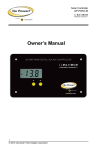
 Transfer Switch
GP-TS 50
________________________________________________
Owner’s Manual
GP‐TS‐50 ___________________________________________________________ Table of Contents
Introduction
2
Installation
2
Operational Testing
7
Troubleshooting
7
Hi-Pot Testing
8
Generator Note
9
Medical Appliances
10
Caution
10
Disclaimer of Liability and Warranty
10
1. Introduction
The Go Power!™ Transfer Switch 50 (TS-50) provide automatic power switching
between two or three separate 120/240 volt AC input sources, including power
cords, onboard generators, onboard inverters, or all three. The ATS will sense the
presence of available power supplies and automatically select the proper one.
The TS-50 can be installed at the electrical entry of the RV on the line side of the
main distribution panel, or it can be installed on the load side of the panel between
the main panel and a sub panel, allowing switching for either the entire electrical
load or only designated circuits switch ground bar. A direct access hole to the
ground bar is provided through the enclosure for convenience.
Determine proper connections of wire conductors to electrical terminals. On 120
VAC wiring the ground wire is bare or green, the neutral wire is white, and the hot
wire is black. On 240 VAC
2. Installation
2 GP‐TS‐50 ___________________________________________________________ READ AND FOLLOW ALL SAFETY INSTRUCTIONS!
2.1 Disconnect Power
Make sure the generator is off, the external power cord is unplugged, and the
inverter, if any, is shut off.
2.2 Mounting Location
The TS-50 mounting location may be on any interior surface where the unit will be
out of direct weather. The chosen location must be accessible after installation is
complete to facilitate future servicing. If possible, mount the TS-50 near the power
cord entry or the location of the generator output. Typical locations include under
counter cabinets, below closet compartments, inside the bed pedestal or cabinets,
overhead cabinets, under-floor storage compartments accessed from the vehicle
exterior, etc.
2.3 Electrical Preparation
Use knockouts 12, 5, and 6 when installing the TS-50. Do not use knockouts 3, 4,
7, and 8 when preparing the TS-50 for installation.
2.4 Mounting
Mount the TS-50 with screws through holes provided in bottom corners of the can.
The unit should be screwed to a solid surface firmly enough to hold its weight
during vehicle operation.
2.5 Electrical Connections
A. Attach an 8 gauge chassis ground wire to the transfer switch ground bar.
A direct access hole to the ground bar is provided through the enclosure for
convenience.
B. Determine proper connections of wire conductors to electrical terminals.
On 120 VAC wiring the ground wire is bare or green, the neutral wire is
white, and the hot wire is black. On 240 VAC wiring there are two hot wires;
one is black, and the other is red.
C. Strip the outer jacket from all of the incoming cables. Strip insulation from
all ends of the copper conductors. Insert cables through clamps in openings.
Do not tighten cable clamps at this time.
3 GP‐TS‐50 ___________________________________________________________ D. Route internal ground wires around lower area of enclosure and secure
to ground wires away from electrical contacts on components to avoid the
possibility of electrical short-circuit.
E. Connect the ground wires to the ground bar. Tighten terminals to a
minimum of 20 inch-pounds.
F. Connect the neutral (white) wire connections.
G. Connect the hot wire(s). If there is a black wire and a red wire (for 240
VAC), it does not matter which is hot 1 and which is hot 2.
H. In some applications it may be desirable to feed a 120 volt supply, such
as an inverter, into both hot legs of a transfer switch, so that the 120 volt
supply can operate the entire RV load. Although discretion is advised in
designing this into the system, it is acceptable, as long as the connection to
both hot legs is accomplished on the input side of the transfer switch. To do
this, connect the hot from the 120-volt supply, such as an inverter, to hot 1,
and then attach a jumper wire of the same gauge from hot 1 to hot 2.
Consideration should be given to the following:
• The entire load must be 120 volt; you cannot operate a 240 volt load from
a 120 volt supply.
• There may be a load which would be undesirable to run from this
particular 120 volt supply; that load should be isolated when the 120 volt
supply is operating. The TS-50 is sometimes used as a ‘lock-out’ switch to
prevent specific loads from being operated from designated supplies.
Example: preventing a battery charger or air conditioner from running from
an inverter, yet operating from generator or powercord.
I. Tighten cable clamps on switch enclosure.
J. Attach lid. The lid is designed to snap on and should not open without
deliberate effort.
2.5.1 Installation Between Powercord and Generator
(Configuration A)
The TS-50 is designed with an easy-to wire bridge. Refer to Diagram 1 for wiring
lug designations.
1. Connect the powercord neutral to the powercord lug labeled NEUTRAL
WHT.
4 GP‐TS‐50 ___________________________________________________________ 2. Connect powercord hot 1 and hot 2 to powercord lugs HOT 1 BLK and
HOT 2 RED.
3. Connect the generator neutral(s) to generator lug labeled NEUTRAL
WHT.
4. Connect generator hot 1 and hot 2 to generator lugs HOT 1 BLK and HOT
2 RED.
5. Connect output to panel or other destination to the applicable “panel” lugs.
The bypass switch should be in the “off” position (marked “1”).
2.5.2 Installation Between Inverter and Alternating Source
(Configuration B)
For installation between an inverter (default) and another power supply (dominant),
such as the output from a prior powercord/ generator transfer switch, connect the
inverter neutral to “powercord’ lug labeled NEUTRAL WHT, and connect the
inverter hot to “powercord” lugs labeled HOT 1 BLK and HOT 2 RED. Connect the
alternate power supply neutral to “generator” lug NEUTRAL WHT.
Connect alternate power supply hot 1 and hot 2 to “generator” lugs HOT 1 BLK and
HOT 2 RED. Connect the output to applicable “panel” lugs. These connections will
allow any other supply to dominate the inverter, and the inverter output will pass
through the normally closed contacts of the switch. This allows the inverter to
operate only in the absence of the other power supplies, which is ideal for inverters.
Set the timer delay bypass switch of the inverter/alternate source transfer switch to
the ON position.
2.5.3 Installation In Hybrid System With TS-30 For Designated
Circuits (Configuration C)
Install the TS-50 on the line side of the main distribution panel as illustrated in
Configuration A. The TS-30 can be installed between inverter (default) and a
circuit panel supplied by the larger amp alternating power supply (dominant).
Connect the inverter to terminals 7 and 8, and connect the 30-amp branch circuit to
5 and 6.
Connect the designated circuit panel to the output terminals. The inverter will only
supply the load in the absence of the 50 amp power supply, in which case, only the
load designated to the 30 amp branch circuit is supplied. The timer delay bypass
switch on the TS-30 should be in the ON position.
5 GP‐TS‐50 ___________________________________________________________ Diagram 1
6 GP‐TS‐50 ___________________________________________________________ 3. Operational Testing
READ AND FOLLOW ALL SAFETY INSTRUCTIONS
1. Plug in the powercord. If the main panel circuit breakers are switched on,
RV load should operate normally. Unplug the powercord.
2. Start the generator. There is a pre-programmed 20-30 second delay in the
transfer switch. The delay is designed to allow the generator a brief warm-up
period. When the delay completes its cycle the switch should engage and
the RV load should operate normally. An audible click should sound as the
switch engages.
3. Shut down the generator. As the generator winds down the switch should
disengage without chatter or cycling. An audible click should sound as the
switch disengages.
4. Plug in the powercord. Start the generator. After the preprogrammed
delay, the switch should transfer power automatically from the powercord to
the generator. Listen for the audible click as the switch transfers, as there
will likely be no other indication that the switch has engaged. Shut down the
generator and unplug the powercord.
5. On transfer switch arrangements with three power supplies, plug in the
powercord, start the generator, and turn on the inverter. With all three
supplies energized at the same time, the switch will select the generator for
the primary supply choice. Shut down the generator. The switch will transfer
to the powercord. Unplug the powercord. The switch will transfer to the
inverter. The inverter should always be connected so that it is only selected
in the absence of both the other supplies.
4. Troubleshooting
4.1 Low Voltage
Low voltage is harmful to most appliances. Contactor-based transfer switches are
also affected by low voltage; if the voltage level drops far enough the contactor
points will “chatter”. Sustained contact chattering can cause transfer switch
damage. Switches that have been damaged by chattering need to be returned to
the factory for replacement.
7 GP‐TS‐50 ___________________________________________________________ 4.2 General Low Voltage
Low voltage can be caused by low voltage conditions such as an RV park with
inadequate wiring for crowded camper conditions where everyone’s electricity
suffers (brownout). In this case a voltmeter will be helpful and will show a low
voltage reading from the park receptacle, even before the RV is plugged in. When
you experience general low voltage conditions, remember, that brownouts can be
harmful to most appliances. A better alternative might be to utilize the generator
until park voltage conditions improve.
4.3 Localized Low Voltage
Low voltage conditions can be caused by specific situations such as an additional
cord that is too long and too small for the load. Do not attempt to extend the RV
powercord by using a 16-gauge 100-foot extension cord, or any cord not rated for
an RV-size load. A localized low voltage condition will result when a load is turned
on that is larger for what which the cord is designed. As soon as the RV tries to
draw more current than the amount for which the cord is rated, the voltage will fall
within the length of the cord, and the RV will experience low voltage. This is
especially noticeable during in rush current situations such as an air conditioner
start-up. Contactor-based transfer switches are affected by this. The compressor
will try to start, the voltage will drop, which will cause the contactor to drop out, at
which point the voltage will rise to the pre-in rush level. The contacts will chatter
when the A/C compressor kicks in, however the voltage may read normal.
Most meters are not fast enough to record this voltage drop. You can test for low
voltage readings during this inrush cycle by reading voltage at the contactor
terminals while manually holding the contactor plunger down in its closed position.
This will override the chattering condition and the meter will have time to register
the reduced voltage. If this condition exists, identify and correct the low voltage
situation before proceeding further.
4.4 Physical Interference
Some transfer switch models have wiring connections made by wire nuts on 63
leads. Occasionally on these models, the wiring connections will get folded into the
cbox in such a manner that the wiring will interfere with the physical operation of
the relay. Visually inspect for free operation of the relay(s).
5. Hi-Pot Testing
(MANUFACTURING COMPANIES ONLY)
8 GP‐TS‐50 ___________________________________________________________ NOTE: If the hi-pot test is performed from the plug on the powercord, the test may
only hi-pot the cord itself; it may not test the RV wiring beyond the switch. The hipot test should be performed from either the transfer switch output or from the main
panel. Test as follows:
1. Turn on all circuit breakers in the panel.
2. Make sure the generator is off.
3. Make sure the powercord is unplugged. Verify that the prongs on the
powercord plug are protected so that the hipot voltage won’t cause a fault
reading from a short, or cause bodily injury from electrical shock.
4. Turn off or disconnect all appliances that would be damaged by the hi-pot
test.
5. Connect the hi-pot leads to:
a) Transfer switch ground bar
b) Transfer switch output terminals hot 1, hot 2 (if present), and
neutral.
6. Energize the hi-pot and conduct test. This will hi-pot test for leakage
(short) between the current-carrying conductors and the ground in the entire
120/240 VAC circuitry beyond the transfer switch. In most cases it will also
test the powercord itself. Turn off the hi-pot.
7. Do not test the transfer switch generator input. The hi-pot will damage the
time delay control module in the transfer switch. If the generator wires to the
switch must be checked, disconnect the generator wires from the transfer
switch and connect hi-pot test leads to the loose wires. Reconnect wires
after testing.
8. If hi-pot test fails, there is a short in the system. The next step is to isolate
the location of the short. Turn off the main breaker in panel and hi-pot test
again. If the test still fails, the fault is between the switch and the panel. Test
cord for shorted plug. If the test passes, turn on the main breaker, and turn
on all branch breakers except one. Retest each branch circuit individually
until the shorted circuit is isolated. Repair the fault and retest. The hi-pot test
is successful when there are no more fault indications.
6. Generator Note
9 GP‐TS‐50 ___________________________________________________________ It is never advisable to start or stop a generator under load. To prolong the life of
this transfer switch, and the life of the air conditioner, microwave oven and other
appliances, always turn those appliances off before starting or stopping the
generator.
7. Medical Appliances
Go Power!™ will not knowingly sell a Go Power!™ Automatic Transfer Switch for
any life-support application. It is strongly recommended that you do not operate any
life support equipment from a transfer switch. If the switch should malfunction, or
fail to operate due to other external conditions, it is possible that all connected
appliances, including any life support equipment, will also shut down, resulting in a
risk of medical complications and potential loss of life.
8. Caution!
Do not install this or any electrical accessory in the battery compartment, or a
compartment intended for storing flammable liquids or liquids that produce
flammable or explosive fumes such as gasoline, etc. There are components in the
Transfer Switch that, in their normal operation, may cause arcing. In addition, the
act of turning on a light switch or unplugging the cord on an electrical appliance can
cause a spark, which can ignite any combustible liquids or vapors. Therefore, do
not install a transfer switch in a compartment intended for storing flammable liquids,
and never store flammable liquids inside a compartment containing any electrical
device.
9. Disclaimer of Liability & Warranty
Visit www.gpelectric.com for additional product warranty information.
All Go Power!™ Transfer Switches come with a two-year warranty. Go Power!™
warranties all Go Power!™ Transfer Switches in the continental United States and
Canada from defects in materials or workmanship under normal use for two years
from date of retail purchase and will repair or replace any Go Power!™ Transfer
Switch under warranty found to be defective free of charge. This warranty is not
valid against defects resulting from, but not limited to:
• Misuse and/or abuse, neglect, or accident
• Exceeding the unit’s design limits
• Improper installation, including, but not limited to, improper
environmental protection and improper hook-up
• Acts of God, including lightning, floods, earthquakes, fire and high winds
10 GP‐TS‐50 ___________________________________________________________ • Damage in handling, including damage encountered during shipment or
installation
• Outdoor weather
9.1 Repair and Return Information
Visit www.gpelectric.com to read the “frequently asked questions” section of our
website to troubleshoot the problem. If trouble persists:
1. Call your Go Power!™ Technical Support team (1-866-247-6527).
2. Return defective product to place of purchase
11 GP‐TS‐50 ___________________________________________________________ © 2011 GO POWER!™ By Carmanah Technologies
www.gpelectric.com
MOBI_MAN_GP-TS-50_vA_Dec2011
12