1
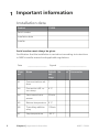
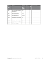
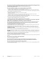
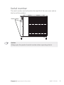
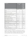
User manual
NIBE™ F2030
LEK
Air/water heat pump
UHB GB 1317-1
231116
Table of Contents
1 Important information
Installation data
Safety information
Safety precautions
Serial number
Contact information
F2030 - An excellent choice
2 The heat pump – the heart of the house
Heat pump function
Contact with F2030
Maintenance of F2030
3 Disturbances in comfort
Troubleshooting
4 Technical data
5 Glossary
Item register
Table of Contents |
2
2
4
5
7
8
10
11
11
13
14
19
19
22
23
28
NIBE™ F2030
1
1 Important information
Installation data
Product
F2030
Serial number
Installation date
Installer
Serial number must always be given
Certification that the installation is carried out according to instructions
in NIBE's installer manual and applicable regulations.
Date
2
__________________
Signed
_________________________
Channel
Name
Default Set
settings
A1
Communications address
1
A3
Connection diff. return temp.
4 °C
A4
Start interval compressor
20 min
A5
Balance temperature
0 °C
A6
Time delay addition
relay
120min
A7
Stop temperature
-20 °C
Chapter 1 | Important information
✔ Accessories
NIBE™ F2030
Channel
Name
A8
Min. interval between 65
defrosting
A9
Start defrosting
-3 °C
A10
Stop defrosting
+20 °C
A14
Activation collar heat- 0
er
A15
Activation de-icing fan 0
A16
Defrosting type
Chapter 1 | Important information
Default Set
settings
✔ Accessories
1
NIBE™ F2030
3
Safety information
This appliance is designed for use in a home environment and not intended to be used by persons (including children) with reduced physical, sensory or mental
capabilities, or lack of experience and knowledge,
unless they have been given supervision or instruction
concerning use of the appliance by a person responsible for their safety. This in accordance to applicable
parts of the low-voltage directive 2006/95/EC, LVD.
The appliance is also intended for use by experts or
trained users in shops, hotels, light industry, on farms
and in similar environments. This in accordance to applicable parts of the machinery directive 2006/42/EC.
Children should be supervised to ensure that they do
not play with the appliance.
This is an original instruction manual. Translation is
not allowed without approval from NIBE.
Rights to make any design or technical modifications
are reserved.
©NIBE 2013.
Symbols
NOTE
This symbol indicates danger to machine or person.
Caution
This symbol indicates important information about what you should observe when maintaining your installation.
TIP
This symbol indicates tips on how to facilitate using the product.
4
Chapter 1 | Important information
NIBE™ F2030
Marking
The CE marking means that NIBE ensures that the product meets all regulations that are placed on it based on relevant EU directives. The CE mark
is obligatory for most products sold in the EU, regardless where they are
made.
Safety precautions
Caution
The installation must be carried out by a qualified installer.
If you install the system yourself, serious problems may occur, for example water leaks,
refrigerant leaks, electric shocks, fire and personal injury, as a result of a system malfunction.
Use original accessories and the stated components for the installation.
If parts other than those stated by us are used, water leaks, electric shocks, fire and
personal injury may occur as the unit may not work properly.
Install the unit in a location with good support.
Unsuitable installation locations can cause the unit to fall and cause material damage
and personal injury. Installation without sufficient support can also cause vibrations and
noise.
Ensure that the unit is stable when installed, so that it can withstand earthquakes
and strong winds.
Unsuitable installation locations can cause the unit to fall and cause material damage
and personal injury.
The electrical installation must be carried out by a qualified electrician and the
system must be connected as a separate circuit.
Power supply with insufficient capacity and incorrect function can cause electric shocks
and fire.
Do not perform any repairs yourself. Consult the dealer if the system requires repair.
Incorrectly performed repairs can cause water leakage, refrigerant leakage, electric
shocks or fire.
Consult the dealer or an expert regarding removal of the heat pump.
Incorrect installation can cause water leakage, refrigerant leaks, electric shocks or fire.
Switch off the power supply in the event of a service or inspection.
If the power supply is not shut off, there is a risk of electric shocks and damage due to
the rotating fan.
Do not run the unit with removed panels or protection.
Touching rotating equipment, hot surfaces or high voltage parts can cause personal
injury due to entrapment, burns or electric shocks.
Cut the power before starting electrical work.
Failure to cut the power can cause electric shocks, damage and incorrect function of
the equipment.
Care
Do not use the unit where water splashes may occur, for example in laundries.
The indoor section is not waterproof and electric shocks and fire can therefore occur.
Chapter 1 | Important information
NIBE™ F2030
5
Do not use the unit for specialist purposes such as for storing food, cooling precision
instruments, freeze-conservation of animals, plants or art.
This can damage the items.
Do not install the outdoor unit in the locations stated below.
- Locations where leakage of combustible gas can occur.
- Locations where carbon fibre, metal powder or other powder that can enter the air.
- Locations where substances that can affect the unit, for example, sulphide gas, chlorine,
acid or alkaline substances can occur.
- Locations with direct exposure to oil mist or steam.
- Vehicles and ships.
- Locations where machines that generate high frequency harmonics are used.
- Locations where cosmetic or special sprays are often used.
- Locations that can be subjected to direct salty atmospheres. In this case, the outdoor
unit must be protected against direct intakes of salty air.
- Locations where large amounts of snow occur.
- Locations where the system is exposed to chimney smoke.
If the bottom frame of the outdoor section is corroded, or in any other way damaged, due to long periods of operation, it must not be used.
Using an old and damaged frame can cause the unit to fall and cause personal injury.
Do not allow the drainage pipe to exit into channels where poisonous gases,
containing sulphides for example, can occur.
If the pipe exits into such a channel, any poisonous gases will flow into the room and
seriously affect the user's health and safety.
Insulate the unit's connection pipes so that the ambient air moisture does not
condense on them.
Insufficient insulation can cause condensation, which can lead to moisture damage on
the roof, floor, furniture and valuable personal property.
Do not install the outdoor unit in a location where insects and small animals can
inhabit.
Insects and small animals can enter the electronic parts and cause damage and fire. Instruct the user to keep the surrounding equipment clean.
Dispose of any packaging material correctly.
Any remaining packaging material can cause personal injury as it may contain nails and
wood.
Do not touch any buttons with wet hands.
This can cause electric shocks.
Do not shut off the power supply immediately after operation has start.
Wait at least 5 minutes, otherwise there is a risk of water leakage or breakdown.
Do not control the system with the main switch.
This can cause fire or water leakage. In addition, the fan can start unexpectedly, which
can cause personal injury.
6
Chapter 1 | Important information
NIBE™ F2030
Serial number
The serial number can be found at the top left of the rear cover and on
the foot of the product.
6HULDO QXPEHU
Caution
Always give the product's serial number when reporting a fault.
Chapter 1 | Important information
NIBE™ F2030
7
Contact information
AT KNV Energietechnik GmbH, Gahberggasse 11, 4861 Schörfling
Tel: +43 (0)7662 8963-0 Fax: +43 (0)7662 8963-44 E-mail: [email protected]
www.knv.at
CH NIBE Wärmetechnik AG, Winterthurerstrasse 710, CH-8247 Flurlingen
Tel: (52) 647 00 30 Fax: (52) 647 00 31 E-mail: [email protected] www.nibe.ch
CZ Druzstevni zavody Drazice s.r.o, Drazice 69, CZ - 294 71 Benatky nad
Jizerou
Tel: +420 326 373 801 Fax: +420 326 373 803 E-mail: [email protected]
www.nibe.cz
DE NIBE Systemtechnik GmbH, Am Reiherpfahl 3, 29223 Celle
Tel: 05141/7546-0 Fax: 05141/7546-99 E-mail: [email protected]
www.nibe.de
DK Vølund Varmeteknik A/S, Member of the Nibe Group, Brogårdsvej 7,
6920 Videbæk
Tel: 97 17 20 33 Fax: 97 17 29 33 E-mail: [email protected] www.volundvt.dk
FI NIBE Energy Systems OY, Juurakkotie 3, 01510 Vantaa
Puh: 09-274 697 0 Fax: 09-274 697 40 E-mail: [email protected] www.nibe.fi
FR AIT France, 10 rue des Moines, 67000 Haguenau
Tel : 03 88 06 24 10 Fax : 03 88 06 90 15 E-mail: [email protected] www.nibe.fr
GB NIBE Energy Systems Ltd, 3C Broom Business Park, Bridge Way,
Chesterfield S41 9QG
Tel: 0845 095 1200 Fax: 0845 095 1201 E-mail: [email protected]
www.nibe.co.uk
NL NIBE Energietechniek B.V., Postbus 2, NL-4797 ZG WILLEMSTAD (NB)
Tel: 0168 477722 Fax: 0168 476998 E-mail: [email protected] www.nibenl.nl
NO ABK AS, Brobekkveien 80, 0582 Oslo, Postadresse: Postboks 64 Vollebekk,
0516 Oslo
Tel. sentralbord: +47 23 17 05 20 E-mail: [email protected] www.nibeenergysystems.no
PL NIBE-BIAWAR Sp. z o. o. Aleja Jana Pawła II 57, 15-703 BIAŁYSTOK
Tel: 085 662 84 90 Fax: 085 662 84 14 E-mail: [email protected]
www.biawar.com.pl
RU © "EVAN" 17, per. Boynovskiy, Nizhny Novgorod
Tel./fax +7 831 419 57 06 E-mail: [email protected] www.nibe-evan.ru
8
Chapter 1 | Important information
NIBE™ F2030
SE NIBE AB Sweden, Box 14, Hannabadsvägen 5, SE-285 21 Markaryd
Tel: +46-(0)433-73 000 Fax: +46-(0)433-73 190 E-mail: [email protected]
www.nibe.se
For countries not mention in this list, please contact Nibe Sweden or check www.nibe.eu
for more information.
Chapter 1 | Important information
NIBE™ F2030
9
F2030 - An excellent choice
F2030 is an air/water heat pump specially developed for the Nordic climate,
which utilises the outside air so there is no need for bore holes or coils in
the ground.
The heat pump is intended for connection to water borne heating systems
and can both heat hot water effectively at high outdoor temperatures
and give a high output to the heating system at low outdoor temperatures.
If the outdoor temperature drops to a level below the stop temperature
all heating must then occur with external additional heat.
Excellent properties for F2030:
႑
Efficient scroll compressor
New efficient scroll compressor that operates at temperatures down
to -25°C.
႑
Intelligent control
Integrated intelligent control for optimum control of the heat pump.
At a start signal from an NIBE indoor module or thermostat F2030 is
started.
႑
Fan
F2030 has an automatic 2-step capacity regulator for the fan.
႑
Long service life
The material has been chosen for a long service life and is designed to
withstand the Nordic outdoor conditions.
႑
Many possibilities
F2030 can also be used together with most electric boilers, oil boilers
or similar.
႑
Quiet
F2030 has a very low noise level.
႑
Draining
F2030 has been prepared to lead off the condensation water.
10
Chapter 1 | Important information
NIBE™ F2030
2 The heat pump – the heart of
the house
Heat pump function
H
+HDWLQJ PHGLXP
5HIULJHUDQW
I
%ULQH
45 °C
55 °C
G
E
80 °C
&RQGHQVHU
Kondensor
Expansionsventil
([SDQVLRQ
YDOYH
F
0 °C
Kompressor
&RPSUHVVRU
Förångare
(YDSRUDWRU
D
5 °C
C
B
-3 °C
+HDW VRXUFH
A
2 °C
The temperatures are only examples and may vary between different installations and
time of year.
Chapter 2 | The heat pump – the heart of the house
NIBE™ F2030
11
An air/water heat pump can use the outdoor air to heat a property. The
conversion of the outdoor air's energy to property heating occurs in three
different circuits. In the brine circuit, (1) , free heat energy is retrieved from
the surroundings and transported to the heat pump. In the refrigerant
circuit, (2) , the heat pump increases the retrieved heat's low temperature
to a high temperature. In the heating medium circuit, (3) , the heat is distributed around the house.
A
B
C
D
E
F
G
H
Outdoor air
The outdoor air is sucked into the heat pump.
The fan then routes the air to the heat pump’s evaporator. Here, the air releases
the heating energy to the refrigerant and the air's temperature drops. The
cold air is then blown out of the heat pump.
Refrigerant circuit
A gas circulates in a closed system in the heat pump, a refrigerant, which also
passes the evaporator. The refrigerant has a very low boiling point. In the
evaporator the refrigerant receives the heat energy from the outdoor air and
starts to boil.
The gas that is produced during boiling is routed into an electrically powered
compressor. When the gas is compressed, the pressure increases and the gas's
temperature increases considerably, from 5 °C to approx. 80°C.
From the compressor, gas is forced into a heat exchanger, condenser, where
it releases heat energy to the heating system in the house, whereupon the
gas is cooled and condenses to a liquid form again.
As the pressure is still high, the refrigerant can pass an expansion valve, where
the pressure drops so that the refrigerant returns to its original temperature.
The refrigerant has now completed a full cycle. It is routed to the evaporator
again and the process is repeated.
Heat medium circuit
The heat energy that the refrigerant produces in the condenser is retrieved
by the climate system's water, heating medium, which is heated to 55 °C
(supply temperature).
The heating medium circulates in a closed system and transports the heated
water's heating energy to the house water heater and radiators/heating coils.
The temperatures are only examples and may vary between different installations and
time of year.
12
Chapter 2 | The heat pump – the heart of the house
NIBE™ F2030
Contact with F2030
F2030 has an integrated control system that checks and monitors the heat
pump operation. At installation the installer makes the necessary settings
of the control system so that the heat pump will work optimally in your
system.
The heat pump is controlled in different ways depending on what your
system looks like. If you have a NIBE indoor module heat pump operation
can be controlled from there. Refer to the relevant manual for further information.
Chapter 2 | The heat pump – the heart of the house
NIBE™ F2030
13
Maintenance of F2030
Regular checks
When your heat pump is located outdoors some external maintenance is
required.
NOTE
Insufficient oversight can cause serious damage to F2030 which is not
covered by the guarantee.
Checking grilles
Check that the inlet grille is not clogged by leaves, snow or anything else
regularly throughout the year.
Pay extra attention in event of high winds or snowfall that may cause the
grille to be blocked.
LEK/APH
Prevent snow building up and covering the grille on F2030.
14
Chapter 2 | The heat pump – the heart of the house
NIBE™ F2030
LEK/APH
Keep free of snow and/or ice.
Cleaning the outer casing
If necessary the outer casing can be cleaned using a damp cloth.
Care must be exercised so that the heat pump is not scratched when
cleaning. Avoid spraying water into the grilles or the sides so that water
penetrates into F2030. Prevent F2030 coming into contact with alkaline
cleaning agents.
Condensation drain pan and condensation water pipe
The trough and drain pipe may require cleaning from leaves or similar
during the year.
Cleaning
1. Use the safety switch to cut the incoming electrical supply.
2. Release the trough using the quick release catches on the left and
right front edges. Keep in position at the rear edge without stretching
the power cable.
3. Clean drain pans and condensation water pipe/drains.
4. Reinstall the trough using the removal method in reverse order (see
point 2).
5. Switch on the safety switch again.
In event of long power cuts
In the event of prolonged power failures it is recommended that the part
of the heating system located outdoors is drained. Your installer has installed a shut off and drain valve to facilitate this. Call and ask your installer
if you are unsure.
Chapter 2 | The heat pump – the heart of the house
NIBE™ F2030
15
Saving tips
Your heat pump installation produces heat and/or hot water. This occurs
via the control settings you made.
Factors that affect the energy consumption are, for example, indoor temperature, hot water consumption, the insulation level of the house and
whether the house has many large window surfaces. The position of the
house, e.g. wind exposure is also an affecting factor.
Also remember:
႑
Open the thermostat valves completely (except those thermostats in
the rooms that are to be kept cooler for various reasons, e.g. bedrooms).
The thermostats slow the flow in the heating system, which the heat
pump wants to compensate with increased temperatures. It then works
harder and consumes more electrical energy.
႑
Reduce or adjust the settings for heating in any external control systems.
Power consumption
RI DQQXDO
FRQVXPSWLRQ
7KH DLUZDWHU KHDW SXPS
V HQHUJ\ GLVWULEXWLRQ VSUHDG DFURVV WKH \HDU
25%
20%
15%
10%
5%
0%
-DQ
jan
)HE
feb
0DU
mars
$SULO
april
0D\
maj
-XQH
juni
-XO\
juli
$XJ
aug
6HS
sep
2FW
okt
1RY
nov
'HF
dec
0RQWK
Increasing the indoor temperature one degree increases power consumption by approx. 5%.
Domestic electricity
In the past it has been calculated that an average Swedish household has
an approximate annual consumption of 5000 kWh domestic electricity/year. In today's society it is usually between 6000-12.000 kWh/year.
16
Chapter 2 | The heat pump – the heart of the house
NIBE™ F2030
Equipment
Flat-screen (Operation: 5 h/day, Standby: 19
h/day)
Digital box (Operation: 5 h/day, Standby: 19
h/day)
DVD (Operation: 2 h/week)
TV games console (Operation: 6 h/week)
Radio/stereo (Operation: 3 h/day)
Computer incl. screen (Operation: 3 h/day,
standby 21 h/day)
Bulb (Operation 8 h/day)
Spot light, Halogen (Operation 8 h/day)
Cooler (Operation: 24 h/day)
Freezer (Operation: 24 h/day)
Oven, hob (Operation: 40 min/day)
Oven (Operation: 2 h/week)
Dishwasher, cold water connection (Operation 1 time/day)
Washing machine (Operation: 1 time/day)
Tumble drier (Operation: 1 time/day)
Vacuum cleaner (Operation: 2 h/week)
Engine block heater (Operation: 1 h/day, 4
months a year)
Passenger compartment heater (Operation:
1 h/day, 4 months a year)
Normal Output
(W)
Approximate
annual
consumption
(kWh)
Operation Standby
200
2
380
11
10
90
15
160
40
100
5
2
1
2
45
67
50
120
60
20
100
120
1500
3000
2000
-
175
55
165
380
365
310
730
2000
2000
1000
400
-
730
730
100
50
800
-
100
These values are approximate example values.
Example: A family with 2 children live in a house with 1 flat-screen TV, 1
digital box, 1 DVD player, 1 TV games console, 2 computers, 3 stereos, 2
bulbs in the WC, 2 bulbs in the bathroom, 4 bulbs in the kitchen, 3 bulbs
outside, a washing machine, tumble drier, fridge, freezer, oven, vacuum
cleaner, engine block heater = 6240 kWh domestic electricity/year.
Chapter 2 | The heat pump – the heart of the house
NIBE™ F2030
17
Energy meter
Check the accommodation's energy meter regularly, preferably once a
month. This will indicate any changes in power consumption.
Newly built houses usually have twin energy meters, use the difference to
calculate your domestic electricity.
New builds
Newly built houses undergo a drying out process for a year. The house
can then consume significantly more energy than it would thereafter.
After 1-2 years the heating curve should be adjusted again, as well as the
heating curve offset and the building's thermostat valves, because the
heating system, as a rule, requires a lower temperature once the drying
process is complete.
18
Chapter 2 | The heat pump – the heart of the house
NIBE™ F2030
3 Disturbances in comfort
Troubleshooting
NOTE
Work behind covers secured by screws may only be carried out by, or under
the supervision of, a qualified installation engineer.
NOTE
As F2030 can be connected to a large number of external units, these
should also be checked.
NOTE
If the operating disturbance cannot be rectified by means of this chapter,
an installation engineer should be called.
NOTE
In the event of action to rectify malfunctions that require work within
screwed hatches the incoming electricity must isolated at the safety switch.
The following tips can be used to rectify comfort disruption:
Basic actions
Start by checking the following possible fault sources:
႑
That the heat pump is running or that the supply cable to F2030 is
connected.
႑
Group and main fuses of the accommodation.
႑
The property's earth circuit breaker.
Low hot water temperature or a lack of hot water
This part of the fault-tracing chapter only applies if the heat pump is docked
to the hot water heater.
႑
Large hot water consumption.
႑ Wait until the hot water has heated up.
Chapter 3 | Disturbances in comfort
NIBE™ F2030
19
႑
Incorrect settings in the NIBE indoor module.
႑ See the manual for the indoor module.
Low room temperature
႑
Closed thermostats in several rooms.
႑ Set the thermostats to max in as many rooms as possible.
႑
External switch for changing the room heating activated.
႑ Check any external switches.
႑
Incorrect settings in NIBE SMO or NIBE indoor module
႑ See the manual for the indoor module.
High room temperature
႑
External switch for changing the room heating activated.
႑ Check any external switches.
႑
Incorrect settings in NIBE SMO or NIBE indoor module
႑ See the manual for the indoor module.
F2030 is not operational
႑
External control equipment has not given the start signal.
႑ Check the settings on the control equipment.
႑
Fuses have tripped.
႑ Replace the fuse or reset the MCB. If the fuse trips again the installation engineer should be contacted.
႑
Cold outdoor air.
႑ Wait until the ambient temperature is 2 °C higher than the heat
pump’s set stop value.
႑
Ambient temperature is hotter than 40 °C.
႑ Wait until the ambient temperature is colder than 38 °C.
႑
Low evaporation temperature.
႑ Ensure that the air flow is not blocked. If the fault remains contact
the installation engineer.
႑
Time conditions do not permit start.
႑ Wait until the set conditions have run out.
Ice build up in the fan collar
Contact your installer!
20
Chapter 3 | Disturbances in comfort
NIBE™ F2030
Ice build up on the fan blades and front grille
Contact your installer!
Chapter 3 | Disturbances in comfort
NIBE™ F2030
21
4 Technical data
Detailed technical specifications for this product can be found in the installation manual (www.nibe.eu).
22
Chapter 4 | Technical data
NIBE™ F2030
5 Glossary
Additional heat:
The additional heat is the heat produced in addition to the heat supplied
by the compressor in your heat pump. Additional heaters can be for example, immersion heater, electric heater, solar power system,
gas/oil/pellet/wood burner or district heating.
Ambient temperature sensor
A sensor that is located outdoors on or close to the heat pump. This sensor
tells the heat pump how hot it is where the sensor is located.
Balance temperature
The balance temperature is the outdoor temperature when the heat
pump’s stated output is equal to the building’s output requirement. This
means that the heat pump covers the whole building’s output requirement
down to this temperature.
Charge coil
A charge coil heats the domestic hot water (tap water) in the heater with
heating water from F2030.
Charge pump
See "Circulation pump".
Circulation pump
Pump that circulates liquid in a pipe system.
Climate system
Climate systems can also be called heating systems. The building is heated
using radiators, under floor coils or convector fans.
Coil tank
A heater with a coil in it. The water in the coil heats the water in the
heater.
Chapter 5 | Glossary
NIBE™ F2030
23
Compressor
Compresses the gas state refrigerant. When the refrigerant is compressed,
the pressure and the temperature increase.
Condenser
Heat exchanger where the hot gas state refrigerant condenses (cooled
and becomes a liquid) and releases heat energy to the house heating and
hot water systems.
COP
If it is stated that a heat pump has COP 4, this means, in principle that if
you insert 10 pence, you will get 40 pence worth of heat. It is the efficiency
of the heat pump. This is measured at different measurement values, e.g.:
7/45 where 7 stands for the outdoor temperature and 45 for how many
degrees the supply temperature is.
Disturbances in comfort
Disturbances in comfort are undesirable changes to the hot water/indoor
comfort, for example when the temperature of the hot water is too low
or if the indoor temperature is not at the desired level.
A malfunction in the heat pump can sometimes be noticed in the form of
a disturbance in comfort.
In most cases, the heat pump notes malfunctions and indicates this with
alarms in the display.
Domestic hot water
The water one showers in for example.
Double-jacketed tank
A heater with domestic hot water (tap water) is surrounded by an outer
vessel with boiler water (to the house radiators/elements). The heat pump
heats the boiler water, which in addition to going out to the all the house
radiators/elements, heats the domestic hot water in the inner vessel.
Efficiency
A measurement of how effective the heat pump is. The higher the value
is the better it is.
24
Chapter 5 | Glossary
NIBE™ F2030
Electrical addition
This is electricity that, for example, an immersion heater uses as addition
during the coldest days of the year to cover the heating demand that the
heat pump cannot manage.
Evaporator
Heat exchanger where the refrigerant evaporates by retrieving heat energy
from the air which then cools.
Expansion valve
Valve that reduces the pressure of the refrigerant, whereupon the temperature of the refrigerant drops.
Expansion vessel
Vessel with heating medium fluid with the task of equalising the pressure
in the heating medium system.
Flow pipe
The line in which the heated water is transported from the heat pump out
to the house heating system (radiators/heating coils).
Heat exchanger
Device that transfers heat energy from one medium to another without
mixing mediums. Examples of different heat exchangers are evaporators
and condensers.
Heat factor
Measurement of how much heat energy the heat pump gives off in relation
to the electric energy it needs to operate. Another term for this is COP.
Heating medium
Hot liquid, usually normal water, which is sent from the heat pump to the
house climate system and makes the accommodation warm. The heating
medium also heats the hot water.
Heating medium side
Pipes to the house’s climate system make up the heating medium side.
Chapter 5 | Glossary
NIBE™ F2030
25
Hot water heater
Container where domestic water is heated. Is located somewhere outside
the heat pump.
Pressostat
Pressure switch that triggers an alarm and/or stops the compressor if nonpermitted pressures occur in the system. A high pressure pressostat trips
if the condensing pressure is too great. A low pressure pressostat trips if
the evaporation pressure is too low.
Radiator
Another word for heating element. They must be filled with water in order
to be used with F2030.
Refrigerant
Substance that circulates around a closed circuit in the heat pump and
that, through pressure changes, evaporates and condenses. During evaporation, the refrigerant absorbs heating energy and during condensing,
gives off heating energy.
Return pipe
The line in which the water is transported back to the heat pump from
the house heating system (radiators/heating coils).
Return temp
The temperature of the water that returns to the heat pump after releasing
the heat energy to the radiators/heating coils.
Safety valve
A valve that opens and releases a small amount of liquid if the pressure is
too high.
Shuttle valve
A valve that can send liquid in two directions. A shuttle valve that enables
liquid to be sent to the climate system, when the heat pump produces
heating for the house, and to the hot water heater, when the heat pump
produces hot water.
26
Chapter 5 | Glossary
NIBE™ F2030
Supply temperature
The temperature of the heated water sent by the heat pump to the heating
system.
Chapter 5 | Glossary
NIBE™ F2030
27
6 Item register
C
Contact information, 8
Contact with F2030, 13
Control module's function, 11
D
Disturbances in comfort
Troubleshooting, 19
F
F2030 – An excellent choice, 10
G
Glossary, 23
H
Heat pump function, 12
I
Important information, 2
Contact information, 8
F2030 – An excellent choice, 10
Installation data, 2
Serial number, 7
In event of long power cuts, 15
28
Chapter 6 | Item register
Installation data, 2
M
Maintenance of F2030, 14
In event of long power cuts, 15
Regular checks, 14
Saving tips, 16
P
Power consumption , 16
R
Regular checks, 14
S
Safety precautions, 5
Saving tips, 16
Power consumption , 16
Serial number, 7
T
Technical data, 22
The heat pump – the heart of the
house, 11
Troubleshooting, 19
NIBE™ F2030
NIBE AB Sweden
Hannabadsvägen 5
Box 14
SE-285 21 Markaryd
[email protected]
www.nibe.eu
231116