1
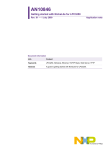
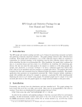
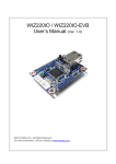
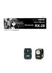
.
GRESB User's Manual
1
GRESB User's Manual
GRESB User's Manual
GRESB-UM
Version 1.5.12
november 2015
Kungsgatan 12
411 19 Gothenburg
Sweden
tel +46 31 7758650
fax +46 31 421407
www.aeroflex.com/gaisler
GRESB User's Manual
GRESB User's Manual
Copyright © 2015 Cobham Gaisler AB
2
GRESB User's Manual
iii
Table of Contents
1. Introduction ...................................................................................................................... 1
1.1. System overview .................................................................................................... 1
2. Installation ....................................................................................................................... 2
2.1. Power ................................................................................................................... 2
2.2. Ethernet ................................................................................................................ 2
2.3. SpaceWire links ..................................................................................................... 2
2.4. GRESB Console ..................................................................................................... 2
3. Operation ......................................................................................................................... 3
3.1. Overview ............................................................................................................... 3
3.2. Host to SpaceWire packet transmission ....................................................................... 6
3.3. SpaceWire to host packet reception ............................................................................ 6
3.4. Packet Sniffing reception ......................................................................................... 6
3.5. GRESB configuration .............................................................................................. 7
3.5.1. Transmission bit rate configuration (option = 1) ................................................. 7
3.5.2. Routing table configuration (option = 2) ........................................................... 7
3.5.3. Enable/disable link (option = 3) ...................................................................... 8
3.6. GRESB status query ................................................................................................ 8
3.6.1. Link status (option = 0) ................................................................................. 8
3.6.2. Link statistics (option = 1) ............................................................................. 9
3.6.3. Node address statistics (option = 2) ................................................................. 9
3.6.4. Get route (option = 3) ................................................................................... 9
3.7. Send time-code ..................................................................................................... 10
3.8. Read/write GPIO protocol ...................................................................................... 10
3.9. GRESB network settings ........................................................................................ 11
3.10. Host software ..................................................................................................... 11
3.10.1. GRMON ................................................................................................. 12
3.10.2. SpaceWire IP tunnel software ...................................................................... 13
3.11. GRESB embedded web server ............................................................................... 14
4. Optional CAN 2.0B interface ............................................................................................. 16
4.1. Overview ............................................................................................................. 16
4.2. CAN message transmission and reception .................................................................. 16
4.3. CAN configuration ................................................................................................ 16
4.3.1. Bus timing configuration (option = 0) ............................................................. 17
4.3.2. Acceptance filter configuration (option = 1 and 2) ............................................. 18
4.4. CAN status .......................................................................................................... 18
4.5. Software .............................................................................................................. 20
5. Interfaces ....................................................................................................................... 21
5.1. Front panel .......................................................................................................... 21
5.2. Back panel ........................................................................................................... 21
5.3. Connector pin-out tables ......................................................................................... 22
6. Mechanical box drawings .................................................................................................. 23
GRESB User's Manual
1
1. Introduction
1.1. System overview
The GRESB bridge is developed to facilitate rapid development and testing of equipment with SpaceWire
interfaces. It provides three bi-directional SpaceWire links with a maximum bit rate of 100 Mbit/s and six
“virtual” links that are interfaced through TCP sockets. Each SpaceWire link can be individually configured
with respect of transmission bit rate. When a packet arrives to the GRESB bridge on any of the links (real
or virtual) it is forwarded to the link specified in the routing table.
This allows a developer to generate SpaceWire test data on a workstation and send the data with TCP/IP
to the bridge where it is sent out on the appropriate link. In the same manner data received on each of the
three SpaceWire links can be routed to the workstation or to other SpaceWire equipment. The aggregate
throughput of the bridge is 25 Mbit/s when connected to a 100 Mbit/s full duplex ethernet network with
ideal conditions.
Using the GRMON debug monitor target systems equipped with a SpaceWire core with RMAP sup- port
can be debugged through the bridge.
In extension to its three SpaceWire links the bridge can optionally be equipped with a CAN 2.0B compatible
interface, see separate chapter.
Figure 1.1. GRESB system diagram
The bridge can be configured with a static ip address or use the built-in DHCP client to automatically acquire
an IP address when connected to an ethernet network. An embedded web server displays information about
the system and lets the user configure the GRESB. The configured IP address is printed on the serial console
(USB-SERIAL connector) during boot.
GRESB User's Manual
2
2. Installation
2.1. Power
The GRESB is powered from an external +5V adapter, which should be connected to POWER in the back
panel.
2.2. Ethernet
The connection to the ethernet network should be done using a standard network cable, inserted in the RJ45
connector (ETHERNET) in the front panel. In order to switch between 10/100 Mbps or 1000 Mbps Ethernet
interface, the GRESB device has to perform a reset.
2.3. SpaceWire links
GRESB provides three SpaceWire interfaces using nine contact female micro-miniature D-type connectors
(MDM) or standard D-type connectors (D9) in the back panel (SPW0 - SPW2). The pin layout of these
connectors is compatible with the SpaceWire standard.
2.4. GRESB Console
The GRESB console is provided on USB Mini-B port on the front panel (USB-SERIAL). It operates on
38400 baud, and should be connected to the host computer. A terminal emulation software such as Hyperterm
or Minicom should be used to monitor the console.
Figure 2.1. GRESB installation
GRESB User's Manual
3
3. Operation
3.1. Overview
Each virtual SpaceWire link consists of a pair of TCP sockets, one for transmit data and one for received
data. Table 1 lists the ports allocated for each virtual link. The GRESB listens for incoming connections on
these ports. A host computer should connect to a virtual link using the standard connect() socket call.
All communication on these ports follow a simple protocol described in Section 3.2, “Host to SpaceWire
packet transmission” and Section 3.3, “SpaceWire to host packet reception”.
Table 3.1. GRESB TCP port allocation
Port
Function
3000
Virtual link 0 transmit
3001
Virtual link 0 receive
3002
Virtual link 1 transmit
3003
Virtual link 1 receive
3004
Virtual link 2 transmit
3005
Virtual link 2 receive
3006
Virtual link 3 transmit
3007
Virtual link 3 receive
3008
Virtual link 4 transmit
3009
Virtual link 4 receive
3010
Virtual link 5 transmit
3011
Virtual link 5 receive
3064
Traffic Sniffer
80
Web server
When a packet is received on any link (real or virtual) the destination node address is used to index the
routing table in the GRESB. Each entry in the table consists of the following data:
Table 3.2. Routing table entry
Field
Description
Link type
SpaceWire or virtual link.
Link ID
Link number. 0-2 for SpW links and 0-5 for virtual links.
Header deletion
If enabled, delete the first byte in the SpW packet. Makes path addressing possible.
Header deletion
If enabled, delete the first byte in the SpW packet. Makes path addressing possible.
Enabled
Enable the route. If disabled all packets to the node address are dropped.
Sniff
If enabled, the packet will also be sent to the Traffic Sniffer Port if opened.
If the route is not enabled or if the destination link is not active (i.e not in run state or not connected) the
packet is dropped. Otherwise the packet is sent to the link specified in the routing table. Packets that are
forwarded to a SpaceWire link are put in a transmit queue. Each SpaceWire link has a separate queue so a
busy or slow link will not hinder incoming packets destined to another SpaceWire link.
While the GRESB is transmitting a packet to a virtual link (i.e sending data on one of the virtual receive
TCP sockets) it will not process any new packets from the link on which the packet arrived.
Up to 32 incoming SpaceWire packets (with a maximum size of 128 KB) per link are buffered by the bridge
allowing high speed bursts of data. When the buffers are full the SpaceWire flow control capabilities are
used to ensure that no packets are dropped.
GRESB User's Manual
4
The default routing table is set up according to Table 3.3, “Default routing table”.
Table 3.3. Default routing table
Node address
Link type
Link ID
Header deletion
Enabled
0
-
-
-
No
1-3
SpaceWire
0-2
Yes
Yes
4-10
-
-
-
No
11-13
SpaceWire
0-2
No
Yes
14-31
-
-
-
No
32-37
Virtual
0-5
No
Yes
254
SpaceWire
0
No
Yes
Figure 3.1, “GRESB routing” shows how the routing works in the four possible situations, virtual (TCP)
link to SpW link, SpW to TCP, SpW to SpW and TCP to TCP. In separate routing table mode, each port
(TCP and SpaceWire) has it own configurable routing table, the routing still works exactly the same. The
default routing table mode is however to have a single global routing table for all ports.
GRESB User's Manual
5
Figure 3.1. GRESB routing
Example 3.1. TCP to SpW
A packet with Destination Node Address (DNA) 34 is received on virtual link 0. The destination link
is looked up in the routing table. Since it is destined to SpaceWire link 0 it is passed to the appropriate
SpaceWire transmit queue and will be transmitted as soon as possible.
Example 3.2. SpW to TCP
A packet with Destination Node Address (DNA) 35 is received on SpaceWire link 1. The destination link
is looked up in the routing table. It is destined to virtual link 2 and the GRESB will start transmitting the
packet on the appropriate socket.
Example 3.3. SpW to SpW
A packet with Destination Node Address (DNA) 34 is received on SpaceWire link 2. The destination link is
looked up in the routing table. It is destined to SpaceWire link 0 and the packet is passed to the appropriate
SpaceWire transmit queue.
Example 3.4. TCP to TCP
A packet with Destination Node Address (DNA) 33 is received on virtual link 5. The destination link is
looked up in the routing table. It is destined to virtual link 0 and the GRESB will start transmitting the packet
on the appropriate socket.
GRESB User's Manual
6
A packet destined for a virtual link will be dropped if the associated socket is not in a connected state. In a
similar manner a packet will be dropped if the outgoing SpaceWire link is not in run state. When forwarding
to a virtual link, any detected errors (such as error end of packet and truncated packets) are indicated in the
GRESB protocol header. Since this header is not added when forwarding to another SpaceWire link any
possible error information is lost in SpaceWire to SpaceWire routing.
The SpaceWire links have a maximum bit rate of 100 Mbit/s. The transmission bit rate can be divided by
any integer between 1-255 thus giving rates of 100, 50, 33.33, 25, 20, etc. A startup bit rate of 10 Mbit/s as
required by the SpaceWire standard is used. When a link enters run state its bit rate will be changed to the
bit rate configured by the user (which defaults to 10 Mbits/s).
The bridge has a built-in web server on port 80 where the routing table can be modified easily and where
current status and configuration is displayed. Its features are further described in Section 3.11, “GRESB
embedded web server”.
3.2. Host to SpaceWire packet transmission
The transmit ports of the bridge use a simple protocol which can either carry SpaceWire packets or configuration data. Each packet is prepended with a 4 byte header and the first byte in this header always contains a
protocol ID. Packets with protocol ID 0 have a SpaceWire packet as payload. In this case the following three
bytes of the header hold the size of the packet. The header must be sent in network byte order. Figure 3.1,
“GRESB routing” shows the format used when the protocol ID is zero.
Header
1 byte
3 bytes
up to 128Kbytes
prot=0
size
SpaceWire packet
Figure 3.2. Transmit data format
The maximum size of a SpaceWire packet that can be handled by the bridge is 128 Kbytes. It is up to the
host application to correctly create the SpaceWire packets with address, protocol id and data. When sending
RMAP commands the host has to format the SpaceWire packets according to the RMAP protocol including
checksums.
3.3. SpaceWire to host packet reception
SpaceWire data reception is done by connecting to the receive TCP port and reading the desired amount
of SpaceWire packets using a similar protocol as used for transmission. Figure 3.3, “Receive data format”
shows the protocol used for reception. The one byte protocol ID field used for transmission is replaced by
spacewire packet status bits TR (packet received truncated due to maximum length violation) and EP (Packet
ended with an error end of packet character) and 6 reserved bits.
Header
6 bits
1 bit
1 bit
3 bytes
up to 128Kbytes
RES
TR
EP
size
SpaceWire packet
Figure 3.3. Receive data format
The receive TCP port should never be written. If SpaceWire data is received while the TCP port is not bound,
the data will be discarded.
3.4. Packet Sniffing reception
Packet sniffing may be enabled for TCP and for SpaceWire links of a particular destination node address
accoring to the routing table. Packets with a destination address which has sniffing enabled will be delivered
as usual (without sniffing) when no client is connected to the sniff port, and sent to the host on the sniff port
when connected. In order for the user to determine the source port the packet was sniffed upon the Recevie
Data Format has been extended as indicated by the table below.
GRESB User's Manual
7
The SRC Port Type can be either TCP (1) or SpaceWire (0). The SRC Port No indicates atwhich port/link
(0..2 for SpaceWire and 0..5 for TCP) the packet was received.
SIZE is the number of bytes of a complete Sniff packet minus the 4 bytes including RES, TR, EP and SIZE.
NOTE: The first data byte of the sniffed SpaceWire packet is located at offset 7 from the start.
SIZE-9 bytes,
6 bits 1 bit 1 bit 3 bytes
3 bits
1 bit
4 bits
2 bytes
1 byte
5 bytes
max 128KBytes
RES
RES
SRC
PortType
SRC
Port
No.
RES
First
byte in
Packet
Data
RES
Packet Data,
from second byte
and onwards
TR
EP
SIZE
Figure 3.4. Sniff Data Format
The Sniff TCP port should never be written. If SpaceWire data is received while the TCP port is not bound,
the data will be discarded.
3.5. GRESB configuration
It is possible to configure the GRESB through the socket interface. This is done in a similar manner to normal
packet transmission but with the packet structure shown in Figure 3.5, “Configuration protocol format”. The
configuration protocol has ID 1.
Header
1 byte
2 bytes
1 byte
4 bytes
prot=1
Reserved
option
value
Figure 3.5. Configuration protocol format
The two bytes following the protocol ID are reserved for future use and should be set to zero. The last byte
in the header holds the option to be configured. After the header comes a 4 byte value field which also needs
to be in network byte order. The different options and their possible values are listed below.
3.5.1. Transmission bit rate configuration (option = 1)
When configuring the bit rate, option should be set to 1 and value according to Table 3.4, “Value field for
option 1 (bit rate configuration)”.
Table 3.4. Value field for option 1 (bit rate configuration)
byte 3 (MSB)
byte 2
byte 1
byte 0 (LSB)
-
-
SpaceWire link
Clock divisor
3.5.2. Routing table configuration (option = 2)
It is possible to configure all GRESB routing tables through the transmit socket interface. Configuration
packets with option set to 2 and value according to table 6 are used for that purpose.
Byte 3
Byte 2
Byte 1
Byte 0 (LSB)
0
Bit7
Bit0
Bit7-4
1=Save Porttype Port No
table 0=SpW
1=TCP
Bit 3
Bit 2
Bit 1
Bit 0
Bit 7-0
Bit 7-0
1=Sniff 1=Enable 1=Header 1=SpW Link
Link Node address
Traffic 0=Disable deletion 0=Virtual Link number
Enable
enable
Figure 3.6. Value field for Option 2 (routing table configuration)
GRESB User's Manual
8
To save the changed routing table to flash a packet with the most significant bit of the value field set to 1
should be sent. When this bit is set all other bits are ignored. After a save the new settings can be viewed
on the web interface.
Port Type and Port Number is used to identify which routing table is configured. If default routing table
mode is used both these fields should be set to zero to indicate the first routing table (SPW0).
If the specified route is disabled all packets to that destination node address will be dropped.
If header deletion is enabled the first byte will be removed from the SpaceWire packet as it is routed to its
destination link. This needs to be done for path addressing.
The link number should be 0-2 for SpaceWire links and 0-5 for virtual links.
3.5.3. Enable/disable link (option = 3)
When enabling or disabling a link, option should be set to 3 and value according to Table 3.5, “Value field
for option 3 (enable/disable link)”.
Table 3.5. Value field for option 3 (enable/disable link)
byte 3 (MSB)
byte 2
byte 1
byte 0 (LSB)
-
-
SpaceWire link
1=Enable
0=Disable
3.6. GRESB status query
Information about the links, statistics and the routing table can be queried through the socket interface. A
status query is sent in the same manner as a configuration packet but with procotol ID 2. The reply is sent
back on the same socket. The number of words in the reply depends on the option (see below) but each word
is sent in network byte order.
Header
1 byte
2 bytes
1 byte
4 bytes
prot=2
Reserved
option
value
Figure 3.7. Status protocol format
The two bytes following the protocol ID are reserved for future use and should be set to zero. The last byte
in the header holds the option to be configured. After the header comes a 4 byte value field which also needs
to be in network byte order. The different options and their possible values are listed below.
3.6.1. Link status (option = 0)
To query the status of a link the option should be set to 0 and value according to Table 3.6, “Value field
for option 0 (link status)”.
Table 3.6. Value field for option 0 (link status)
Byte 3 (MSB)
Byte 2
Byte 1
Byte 0 (LSB)
-
-
-
Link number (0 - 2)
GRESB User's Manual
9
The link status reply consists of a single word.
Table 3.7. Link status reply
Byte 3 (MSB)
Byte 2
Byte 1
Byte 0 (LSB)
-
-
Clock divisor
1 - In run state
0 - Not in run state
3.6.2. Link statistics (option = 1)
Statistics on each SpaceWire link can be read using status option 1.
Table 3.8. Value field for option 1 (link statistics)
Byte 3 (MSB)
Byte 2
Byte 1
Byte 0 (LSB)
-
-
-
Link number (0 - 2)
The link statistics reply consists of 6 words.
Table 3.9. Link statistics reply
Word
Description
0
Number of packets received
1
Size of data received (MB)
2
Number of packets with EEP received
3
Number of truncated packets received
4
Number of packets transmitted
5
Size of data transmitted (MB)
3.6.3. Node address statistics (option = 2)
Statistics per node address can be read using status option 2.
Table 3.10. Value field for option 2 (node address statistics)
Byte 3 (MSB)
Byte 2
Byte 1
Byte 0 (LSB)
-
-
-
Node address
The reply consists of 2 words
Table 3.11. Node address statistics reply
Word
Description
0
Number of packets routed to node address
1
Number of packets destined to node address that were dropped
3.6.4. Get route (option = 3)
The route for a specified node address can be read using status option 3. In default routing table mode the
Port type and Port number should be set to zero to indicate the global routing table, in separate routing table
mode bit4 indicates Port type (0=SpW, 1=TCP) and bit3-0 indicates for which Port Number (SpW=0-2,
TCP=0-5) the routing table should be changed.
Table 3.12. Value field for option 3 (get route)
Byte 3 (MSB)
Byte 2
Byte 1
Byte 0 (LSB)
-
-
Port Type and Number Node address
indicates which routing
table
GRESB User's Manual
10
The reply consists of a single word.
Table 3.13. Get route reply
Byte 3
Bit 7-0
-
Byte 2
Bit 3
Bit 2
Bit 1
1 = Sniffer 1 = Enabled
enable
0 = Disabled
Bit 0
Byte 1
Byte 0 (LSB)
Bit 7-0
Bit 7-0
1 = Header 1 = SpW link
Link number
deletion
0 = Virtual link
Node address
3.7. Send time-code
Through the socket interface of the GRESB, it is possible to make the spacewire links send out a time-code.
Sending timecode to the TCP links are not supported. A time-code packet is sent in the same manner as a
configuration packet but with procotol ID 3.
Table 3.14. Time-code protocol format
1 byte
1 byte
1 byte
1 byte
prot=3
flags
time
ctrl
3 bytes
1 byte
12 bytes
reserved SPW link mask
reserved
The flags byte is used to control the request. Only bit 0 and bit 1 will have any effect. Bit 0 determines the
time value should be explicitly set or not. Bit 1 determines if the ctrl value should be explicitly set or not.
The time byte will be used as the time value when sending the time-code if bit 0 of the flags byte is set to
1. Otherwise the current time value will be incremented by 1 before being sent.
The ctrl byte will be used as the ctrl value when sending the time-code if bit 1 of the flags byte is set to 1.
Otherwise the current ctrl value will remain unchanged.
The SPW Link mask should be set to specify which spacewire link that will send the time-code, one bit
per spacewire link.
The other 15 bytes are reserved for future use and should be set to zero.
3.8. Read/write GPIO protocol
It is possible to read and write to the GPIO port through the transmit socket interface. A transfer query is
sent in the same manner as a configuration packet but with procotol ID 4. 16 GPIO pins are availabe to user.
A reply is always sent back on the same socket. The reply is described below.
Table 3.15. Read/write GPIO protocol format
1 byte
2 bytes
1 byte
2 bytes 2 bytes 2 bytes
prot=4 reserved option reserved
data
2 bytes
2 bytes 2 bytes 3 bytes
reserved direction reserved
mask
reserved
1 byte
delay
All multi-byte fields must be in network order. The direction, mask and data fields are bit masks where each
bit corresponds to a GPIO pin, i.e. bit 0 corresponds to GPIO0, bit1 to GPIO1 etc.
The two bytes following the protocol ID are reserved ID are reserved for future use and should be set to zero.
If the option byte is set to zero no data will be written to the pins. To write data to the pins, the options
field must be set to 1.
The data field contains the data to be written to the GPIO pins. Data will only be written if option is set to 1.
The direction field sets the direction of the pins. A bit set to 0 will set the corresponding pin to input and
1 to output, The direction configuration be kept after the transaction and it will only be updated if there is
a change in the direction field.
The mask field can be used to select which pins that should be altered. A bit set 1 will use corresponding
pin. If a bit is set to 0, then direction configuration and output data for that pin will remain unchanged. If
all bits are set to zero, no write to the GPIO will occur.
GRESB User's Manual
11
The delay field can be used to insert a small delay before reading the GPIO data, to ensure that the signals
has stabilized. The field specifies minimum number of micro seconds to sleep.
All fields that are reserved should be set to zero.
Table 3.16. GPIO reply format
2 bytes
2 bytes
2 bytes
2 bytes
reserved
data
reserved
direction
The reply is sent back on the same socket in network byte order. It contains the raw values of the input data
and direction. The input data and direction fields are bit masks where each bit corresponds to a GPIO pin,
i.e. bit 0 corresponds to GPIO0, bit1 to GPIO1 etc.
3.9. GRESB network settings
Each bridge is delivered with IP address assigned by the DHCP server in the local network. These settings
can be changed through the web server where also the DHCP client can be activated if you have a DHCP
server on your network and want to acquire the network settings automatically. The chosen IP is printed on
the console uart during boot as shown below:
Command: /sbin/ifconfig
eth0
Link encap:Ethernet HWaddr DE:AD:BE:EF:08:16
inet addr:192.168.0.50 Bcast:192.168.0.255 Mask:255.255.255.0
UP BROADCAST NOTRAILERS RUNNING MTU:1500 Metric:1
RX packets:3 errors:0 dropped:0 overruns:0 frame:0
TX packets:4 errors:0 dropped:0 overruns:0 carrier:0
collisions:0
RX bytes:0 (0.0 iB) TX bytes:0 (0.0 iB)
Base address:0xb00
Command:
Command: /bin/ethspw &
=========================================
GR Ethernet to SpaceWire bridge started
Waiting for connections
=========================================
It is possible to change the network settings through the console using the ‘netcfg’ command:
Set the ip and static configuration: netcfg ip <ip address>
Set the netmask and static configuration: netcfg nm <netmask>
Set the gateway and static configuration: netcfg gw <gateway>
Switch to DHCP: netcfg dhcp
Switch to static configuration: netcfg static
The netcfg command changes the network parameters stored in the FLASH memory. A reboot is necessary
for the changes to take effect.
3.10. Host software
A host software package for communicating with the GRESB is provided with the unit on a CD. The
software includes four programs: send, recv, set_clkdiv, set_route, get_route, get_status, get_linkstats,
get_nodestats and sniff. The syntax of the programs is as follows:
send <ip address> <virtual link> <node address> <file name>
recv <ip address> <virtual link> <file name>
set_clkdiv <ip address> <spw link> <clock divisor>
set_route <ip address> <virtual link> <node address> <link> <“spw”|”tcp”> <hdr del> <enabled>
GRESB User's Manual
12
get_route <ip address> <virtual link> <node address>
get_status <ip address> <virtual link> <link>
get_linkstats <ip address> <virtual link> <link>
get_linkstats <ip address> <virtual link> <node address>
sniff <ip address> <file name>
The send command connects to a virtual link and transmits a file from the host to the GRESB where it is
routed to the desired node. The file is sent in packets of size 32 KBytes. If another packet size is needed
change the SPW_PACKETSIZE in send.c accordingly.
The recv command connects to a virtual link and receives data which is routed to that link. The data is saved
into the file <filename>. The recv program never exits, it must be killed with a ctrl-c.
The set_clkdiv and set_route sends configuration packets configuring the clock divisor and the routing
table.
The sniff command connects to the sniff port of the GRESB logs packet traffic from TCP/SPW ports which
has the destination address sniff field enabled. The packets are stored to file.
Examples:
1. To send a file to SpaceWire node address 10 from virtual link 0
send 192.168.0.103 0 10 file.dat
2. To receive data on virtual link 0 and save it to file data:
recv 192.168.0.103 0 data
3. To set the transmission bit rate of SpaceWire link 0 to 50 Mbits/s, divide the clock by 2:
set_clkdiv 192.168.0.103 0 2
4. To create a route for node address 40 to SpaceWire link 2 with no header deletion.
set_route 192.168.0.103 0 40 2 spw 0 1
4. To save the routing table to flash.
set_route 192.168.0.103 0 save
Source code for the API and example applications is provided on the CD.
The host software can be compiled on either linux or windows/cygwin hosts. The software should be compiled as follows:
gcc
gcc
gcc
gcc
gcc
gcc
gcc
gcc
gcc
-02
-02
-02
-02
-02
-02
-02
-02
-02
send.c ethspw_api.c -o send
recv.c ethspw_api.c -o recv
set_clkdiv.c ethspw_api.c -o set_clkdiv
set_route.c ethspw_api.c -o set_route
get_route.c ethspw_api.c -o get_route
get_status.c ethspw_api.c -o get_status
get_linkstats.c ethspw_api.c -o get_linkstats
get_nodestats.c ethspw_api.c -o get_nodestats
sniff.c ethspw_api.c -o sniff
3.10.1. GRMON
Targets equipped with a SpaceWire core with RMAP support can be debugged through the GRMON debug
monitor using the GRESB. GRMON will connect on a virtual link and send RMAP packets to the specified
destination node address. For the specified source node address a return route to the virtual link on which
GRMON is connected must be set up.
To debug with GRMON through the bridge start with the -gresb switch and use the following switches
to set the needed parameters:
-ip <ipnum> Connect to the bridge using the IP address ipnum. Default is 192.168.0.51.
-link <linknum> Connect to virtual link linknum on the bridge. Defaults to 0.
-dna <dna> The destination node address of the target. Defaults to 0xFE.
GRESB User's Manual
13
-sna <sna> The source node address to set in the RMAP packets. Defaults to 32.
-dkey <key> The destination key used by the targets RMAP interface. Defaults to 0.
-clkdiv <div> Divide the transmitter bit rate by div. If not specified, the current setting is used.
3.10.1.1. Example
The following example shows how to connect to a target which has the SpaceWire default node address
0xFE using virtual link 0:
grmon -gresb -ip 192.168.0.50 -dna 0xfe -sna 32 -link 0
Since the default routing table routes packets with node address 0xFE to SpaceWire link 0 and packets with
node address 32 to virtual link 0 this command can be used without modifying the default routing table.
It is also possible to connect with GRMON using the USB port of the bridge. Use the -grusb switch instead
of -gresb and leave out -ip and -sna. Before connecting through USB the bridge needs to be reset and
the USB cable connected. Wait until the GRESB has booted (10 s) before starting GRMON.
The bridge needs to be reset when switching between using USB and ethernet and the USB cable needs to
be plugged in after the reset.
When using USB the GRMON binary has to be owned by the superuser (root) and have s (set user or group
ID on execution) permission bit set (chmod +s grmon).
3.10.2. SpaceWire IP tunnel software
SpaceWire equipment developed at different sites can easily communicate with each other over any IP
network, for example the Internet, using two GRESB bridges. A tunnel server and client are provided with
the GRESB so that the users can rapidly start their development.
Both the server and the client connects to their respective GRESB on a virtual link and then the client
connects to the server to create a tunnel. Packets received to one of the virtual links are sent across the tunnel
to the other GRESB. The appropriate routes must of course be configured in the respective routing table. If
a secure tunnel is needed then use SSH port forwarding as described later.
Both the server and the client are provided in source code on the CD delivered with the GRESB.
3.10.2.1. Using the SpaceWire IP tunnel server
The server binary on the CD is named spw_tunn_serv and has the possible command line parameters listed
in Table 3.17, “SpaceWire IP tunnel server command line parameters”.
Table 3.17. SpaceWire IP tunnel server command line parameters
Parameter
Description
-ip <ip>
The IP address of the GRESB to which the server shall connect.
-link <nr>
The virtual link of the GRESB to which the server shall connect. Default 0.
-log <log file>
Enable the packet log. Each packet sent through the tunnel will be described in
<log file>.
-data <data file> [P]
Enable the packet data log. The content of each packet will be stored in <data
file>. The format of the packet data log follows the GRESB SpW receive protocol.
If the optional P is added after the filename only the real payload will be logged,
i.e. the headers as well as the first 2 bytes of the SpW packet (node address and
protocol id) will not be stored.
3.10.2.2. Using the SpaceWire IP tunnel client
The client binary on the CD is named spw_tunn_client and has the possible command line parameters listed
in Table 3.18, “SpaceWire IP tunnel client command line parameters”.
GRESB User's Manual
14
Table 3.18. SpaceWire IP tunnel client command line parameters
Parameter
Description
-ip <ip>
The IP address of the GRESB to which the client shall connect.
-link <nr>
The virtual link of the GRESB to which the client shall connect. Default 0.
-rip <rip>
The IP of the host running the server application.
-log <log file>
Enable the packet log. Each packet sent through the tunnel will be described in
<log file>.
-data <data file> [P]
Enable the packet data log. The content of each packet will be stored in <data
file>. The format of the packet data log follows the GRESB SpW receive protocol.
If the optional P is added after the filename only the real payload will be logged,
i.e. the headers as well as the first 2 bytes of the SpW packet (node address and
protocol id) will not be stored.
3.10.2.3. Using SSH port forwarding for a secure connection
It is possible to use SSH port forwarding to make the tunnel secure. On the host running the client application
issue the following commands:
ssh -N -L 3000:<server ip>:3000 <server ip>
ssh -N -L 3001:<server ip>:3001 <server ip>
And leave out the -rip parameter when connecting with the client. This makes the client connect to the
ports on the localhost (127.0.0.1) which are listened on by the SSH application. SSH forwards any data sent
by the client to the server and vice versa.
3.11. GRESB embedded web server
GRESB has an embedded web server (port 80) which allows the user to view status and configure various
parameters. From the main page you can chose between status, network configuration, routing table configuration and firmware upgrade. The status page is shown in Figure 3.8, “Status page”.
Figure 3.8. Status page
On the network configuration page DHCP or static configuration can be selected and the static ip/net-mask
can be specified. These settings are stored in flash when the submit button is pressed. For the changes to
GRESB User's Manual
15
take effect the bridge needs to be rebooted which can be done by pressing the “Reboot” checkbox on the
page before pressing submit. Figure 3.9, “Network configuration page” below shows this page.
Figure 3.9. Network configuration page
From the routing table configuration page the whole routing table can be viewed and any entry can be
modified too suit the user’s needs. It is also possible to reset the table to its default state.
NOTE: Any changes made to the routing table through the socket interface will not show up on the web
interface until they have been saved.
It is possible to update the GRESB’s firmware through the web interface. Updates will be made available on
Gaisler Research’s web site. The firmware images are protected by a checksum and will be stored in RAM
and validated before programmed to flash memory. It is very important not to turn the power off while the
flash is being programmed. Always wait until confirmation has been given that the programming is done.
GRESB User's Manual
16
4. Optional CAN 2.0B interface
4.1. Overview
When the bridge is equipped with a CAN controller it uses the ports listed in Table 4.1, “CAN tcp port
allocation” in addition to the previously listed ports.
Table 4.1. CAN tcp port allocation
Port
Function
4000
CAN transmit
4001
CAN receive
Data received on the CAN transmit port will be interpreted based on the first byte which acts as a protocol
ID. Table 4.2, “CAN bridge protocols” lists the available protocols. The receive port must only be read from
and the data received is always (protocol 0) messages.
The CAN bridge have receive and transmit buffers which buffer up to 200 CAN messages of maximum size.
When the receive buffer is full any incoming messages will be lost.
Table 4.2. CAN bridge protocols
Protocol ID
Function
0
Message transmission protocol
1
Configuration protocol
2
Status protocol
4.2. CAN message transmission and reception
The protocol used for sending and receiving CAN messages through the bridge is shown in Table 4.3, “CAN
bridge message protocol”.
Table 4.3. CAN bridge message protocol
Bits (MSB-LSB)
Byte #
Description
7
6
0
Protocol ID = 0
Prot ID 7-0
1
Control
FF
2-5
ID (32 bit word in network ID 28-0 (bits 31-29 are ignored)
byte order)
6-13
Data byte 1 - DLC
RTR
5
4
3
2
1
-
-
DLC (max 8 bytes)
0
Data byte n 7-0
The control byte specifies Frame Format (FF), standard (FF=0) or extended (FF=1), Remote Transmit Request frame (RTR=1) and the Data Length Code (DLC). The 4 byte ID field holds the CAN identifier and
should use a maximum of 11 bits for standard frames and 29 bits for extended. As many data bytes as specified by the DLC must be sent/read to finish the transfer.
4.3. CAN configuration
The configuration protocol allows for configuring the bus timing and acceptance filter of the CAN controller
in the bridge. The first byte of a configuration packet must be set to 1.
1 byte
1 byte
4 bytes
Prot=1
option
value
Figure 4.1. CAN configuration protocol format
GRESB User's Manual
17
After the protocol ID comes the option field which specifies what option to configure. The value to set for
this option is specified in a 4 byte field which needs to be in network byte order when sent. Available options
are listed in Table 4.4, “CAN options”.
Table 4.4. CAN options
Option
Description
0
Configure bus timing
1
Configure acceptance code
2
Configure acceptance mask
4.3.1. Bus timing configuration (option = 0)
Configuration option 0 is used to set the Bus Timing Registers (BTR) of the CAN controller. The value field
then specifies either one of eight pre configured baud rates or the exact configuration of the registers. The pre
configured baud rates that can be selected and their respective register settings are shown in Table 4.5, “Pre
configured CAN baud rates”. An explanation of the BTR values can be found in Table 4.6, “Bit interpretation
of bus timing 0 register (BTR0)” and Table 4.6, “Bit interpretation of bus timing 0 register (BTR0)”.
Table 4.5. Pre configured CAN baud rates
Baud rate (Kbps)
BTR0
BTR1
20
0xB1
0x7F
40
0x98
0x7F
50
0xB1
0x25
100
0x98
0x25
125
0x93
0x25
250
0x89
0x25
500
0x84
0x25
1000
0x80
0x7F
These configurations all use a synchronization jump width of 3 and has a single sample point located at
68-70% of the bit time.
The baud rate in KBps should be specified in the value field as a 4 byte word in network byte order. Any
other value than those listed above are interpreted as a direct setting of BTR0 and BTR1, e.g. if value is
0x807F then BTR0 will be set to 0x80 and BTR1 to 0x7F.
Table 4.6. Bit interpretation of bus timing 0 register (BTR0)
Bit
Name
Description
BTR0.7-6
SJW
Synchronization jump width
BTR0.5-0
BRP
Baud rate prescaler
The CAN core system clock is calculated as:
tscl = 2*tclk *(BRP+1)
where tclk is the bridge system clock period, 20 ns.
The sync jump width defines how many clock cycles (tscl) a bit period may be adjusted with by one resynchronization.
Table 4.7. Bit interpretation of bus timing 1 register (BTR1)
Bit
Name
Description
BTR1.7
SAM
1 - The bus is sampled three times, 0 - single sample point
GRESB User's Manual
18
Bit
Name
Description
BTR1.6-4
TSEG2
Time segment 2
BTR1.3-0
TSEG1
Time segment 1
The CAN bus bit period is determined by the CAN system clock and time segment 1 and 2 as shown in
the equations below:
tseg1 = tscl * (TSEG1+1)
tseg2 = tscl * (TSEG2+1)
tbit = tseg1 + tseg2 + tscl
The additional tscl term comes from the initial sync segment.
Sampling is done between TSEG1 and TSEG2 in the bit period.
4.3.2. Acceptance filter configuration (option = 1 and 2)
The CAN controller in the bridge can be configured to only accept specific messages using the acceptance
filter. Messages not matching the filter will not be put into the receive fifo. This filter consists of one 32 bit
acceptance code and one 32 bit mask. The code is specified using option 1 and the mask using option 2.
When receiving a standard frame the code is compared against the incoming message in the following way:
•
•
•
•
•
•
Bits 31-21 are compared to ID.28-18.
Bit 20 is compared to the RTR bit.
Bits 19 -16 are unused.
Bits 15-8 are compared to data byte 1.
Bits 7-0 are compared to data byte 2.
The corresponding bits of the mask selects if the results of the comparison doesn’t matter. A set bit in
the mask means don’t care.
When receiving an extended frame the comparison works in the following manner:
•
•
•
•
Bits 31-3 are compared to ID.28-0.
Bit 2 is compared to the RTR bit.
Bits 1-0 are unused.
The corresponding bits in the mask selects if the results of the comparison doesn’t matter. A set bit in
the mask means don’t care.
4.4. CAN status
It is possible to retrieve status about the CAN controller using the status protocol (protocol ID = 2). A two
byte query packet as shown below generates an eight byte status response (which is sent back on the transmit
port).
1 byte
1 byte
Prot=2
option=0
Figure 4.2. CAN status query format
1 byte
1 byte
1 byte
2 byte
1 byte
1 byte
1 byte
Prot=2
option=0
SR
Baud
TXERR
RXERR
Error code
Figure 4.3. CAN status response format
The status web page on a CAN equipped bridge also displays this information.
SR is the contents of the CAN controller status register and it has the bit interpretation shown in Table 4.8,
“Bit interpretation of status register”.
GRESB User's Manual
19
Table 4.8. Bit interpretation of status register
Bit
Name
Description
SR.7
Bus status
1 when the core is in bus-off and not involved in bus activities.
SR.6
Error status
At least one of the error counters have reached or exceeded 96.
SR.5
Transmit status
1 when transmitting a message.
SR.4
Receive status
1 when receiving a message.
SR.3
Transmission complete
1 indicates the last message was successfully transferred.
SR.2
Transmit buffer status
1 means CPU can write into the transmit buffer.
SR.1
Data overrun status
1 if a message was lost because no space in fifo.
SR.0
Receive buffer status
1 if messages available in the receive fifo.
The baud rate is sent as two bytes (MSB first). If it does not match one of the pre configured values it should
be interpreted as BTR0 followed by BTR1.
TXERR and RXERR are the values of the CAN controller’s transmit and receive error counters.
The error code is the value of the CAN controller’s Error Code Capture register which should be interpreted
as below.
Table 4.9. Bit interpretation of error code capture register
Bit
Name
Description
ECC.7-6
Error code
Error code number.
ECC.5
Direction
1 - Reception, 0 - transmission error.
ECC.4-0
Segment
Where in the frame the error occurred.
When a bus error occurs the error code capture register is set according to what kind of error occurred, if it
was while transmitting or receiving and where in the frame it happened. The ECC register will not change
value until it has been read out.
Table 4.10. Error code interpretation
ECC.7-6
Description
0
Bit error
1
Form error
2
Stuff error
3
Other
Table 4.11. Bit interpretation of ECC.4-0
ECC.4-0
Description
0x03
Start of frame
0x02
ID.28 - ID.21
0x06
ID.20 - ID.18
0x04
Bit SRTR
0x05
Bit IDE
0x07
ID.17 - ID.13
0x0F
ID.12 - ID.5
0x0E
ID.4 - ID.0
0x0C
Bit RTR
GRESB User's Manual
ECC.4-0
Description
0x0D
Reserved bit 1
0x09
Reserved bit 0
0x0B
Data length code
0x0A
Data field
0x08
CRC sequence
0x18
CRC delimiter
0x19
Acknowledge slot
0x1B
Acknowledge delimiter
0x1A
End of frame
0x12
Intermission
0x11
Active error flag
0x16
Passive error flag
0x13
Tolerate dominant bits
0x17
Error delimiter
0x1C
Overload flag
20
4.5. Software
An API for communicating with the CAN equipped bridge and example applications are provided on the CD.
GRESB User's Manual
21
5. Interfaces
5.1. Front panel
The front panel of GRESB includes connectors for Ethernet and SpaceWire links.
Figure 5.1. Front-panel
Table 5.1. Front-panel connectors
Name
Function
Type
Description
ETHERNET
Ethernet
RJ45
10/100/1000 Mbit/s Ethernet connector
SPW0
SpaceWire 0
MDM9S or D9 female Spacewire interface 0
SPW1
SpaceWire 1
MDM9S or D9 female Spacewire interface 1
SPW2
SpaceWire 2
MDM9S or D9 female Spacewire interface 2
5.2. Back panel
The back panel contains connectors for power, CAN bus, USB-Serial interface and GPIO interface.
Figure 5.2. Back panel
Table 5.2. Back panel connectors
Name
Function
Type
Description
GPIO
GPIO
2x10pin
header
CAN
CAN bus
D9 male
CAN bus interface
USB-SERIAL
Serial console
USB Mini-B
Serial console, 38400 baud, 8N1
RESET
System reset
Push-button
Performs a system reset of GRESB
ON/OFF
POWER
SPST switch
Power switch to turn on and off GRESB
POWER +5V DC
POWER
2.1 mm JACK
External +5V DC power supply connector
0.1”
pitch General Purpose I/O interface (pin 1-16,
pin 17-18 is +3.3V, pin 19-20 is DGND)
GRESB User's Manual
22
5.3. Connector pin-out tables
Table 5.3. Spacewire connectors (SPW0 - SPW2)
Pin
1
2
3
Name
Description
DIN+
Data In +ve
6 DIN-
Data In -ve
SIN+
Strobe In +ve
7 SIN-
Strobe In -ve
SHIELD
4
5
Inner Shield (connects to DGND)
8 SOUT+
Strobe Out +ve
SOUT-
Strobe Out -ve
9 DOUT+
Data Out +ve
DOUT-
Data Out -ve
The spacewire signal conform to the 2.5V LVDS signalling scheme.
Table 5.4. CAN connector
Pin
1
Name
Description
-
Reserved
6 GND
2
CAN_L
7 CAN_H
3
4
CAN_GND
CAN_L bus line (dominant low)
CAN_H bus line (dominant high)
CAN ground
8 -
Reserved
-
Reserved
9 5
Optional ground (installed)
CAN_SHLD
Unused
Optional CAN shield (not installed)
The CAN connector conform to the recommendations of CiA-DS-102 and CiA DR-303-1. The phys- ical
driver is SN65HVD230, which is compatible with the requirements of the ISO-11898-2 standard two-wire
balanced signaling scheme, supporting speeds up to 1 Mbps. End node termination is provided using 120
Ohm (nominal) resistance.
GRESB User's Manual
6. Mechanical box drawings
Figure 6.1.
23