1
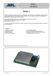
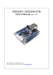
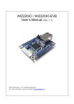
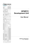
GR-MCC-C ProAsic3E
Development Board
User Manual
AEROFLEX GAISLER AB
Rev. 2.2, 2013-08-28
2
GR-MCC-C ProAsic3E Development Board
User Manual
Information furnished by Aeroflex Gaisler AB is believed to be accurate and reliable.
However, no responsibility is assumed by Aeroflex Gaisler AB for its use, nor for any infringements
of patents or other rights of third parties which may result from its use.
No license is granted by implication or otherwise under any patent or patent rights of Aeroflex
Gaisler AB.
Aeroflex Gaisler AB
tel +46 31 7758650
Kungsgatan 12
fax +46 31 421407
411 19 Göteborg
[email protected]
Sweden
www.aeroflex.com/gaisler
Copyright © 2013 Aeroflex Gaisler
All information is provided as is. There is no warranty that it is correct or suitable for any purpose,
neither implicit nor explicit.
© Aeroflex Gaisler AB
August 2013, Rev. 2.2
3
GR-MCC-C ProAsic3E Development Board
User Manual
TABLE OF CONTENTS
1
INTRODUCTION...........................................................................................................5
1.1
1.2
1.3
1.4
1.5
2
Overview...................................................................................................................... 5
Actel ProASIC3 FPGAs ...............................................................................................7
References...................................................................................................................7
Handling....................................................................................................................... 7
Abbreviations...............................................................................................................7
INTERFACES AND CONFIGURATION.......................................................................9
2.1
2.2
2.3
2.4
2.5
2.6
List of Connectors........................................................................................................9
List of Oscillators........................................................................................................16
List of Switches.......................................................................................................... 16
List of Jumpers........................................................................................................... 16
Note about pin Numbering of expansion connectors..................................................17
List of Test Points......................................................................................................18
LIST OF TABLES
Table 2-1: List of Connectors......................................................................................................... 10
Table 2-2: J1 SPW-0 interface connections .................................................................................11
Table 2-3: J2 SPW-1 interface connections .................................................................................11
Table 2-4: J3 CANBUS interface connections..............................................................................11
Table 2-5: J4a– GPIO Connector ..................................................................................................12
Table 2-6: J4b– GPIO Connector ..................................................................................................12
Table 2-7: J5a– Analog/Power Connector......................................................................................13
Table 2-8: J5b– Analog/Power Connector......................................................................................13
Table 2-9: J6 POWER – External Power Connector......................................................................14
Table 2-10: J7 FPGA– JTAG Connector .......................................................................................14
Table 2-11: Expansion connector J8 Pin-out..................................................................................15
Table 2-12: J9 PIO Header Pin out................................................................................................16
Table 2-13: Expansion connector J10 Pin-out................................................................................16
Table 2-14: List and definition of Oscillators..................................................................................17
Table 2-15: List and definition of Switches.....................................................................................17
Table 2-16: List and definition of PCB Jumpers.............................................................................17
Table 2-17: List of Test Points........................................................................................................18
LIST OF FIGURES
Figure 1-1: GR-MCC-C Development Board...................................................................................6
Figure 1-2: GR-MCC-C Block Diagram...........................................................................................7
Figure 2-1: PCB Top View.............................................................................................................. 19
Figure 2-2: GR-MCC-C Assembly Photo - Top.............................................................................20
© Aeroflex Gaisler AB
August 2013, Rev. 2.2
4
GR-MCC-C ProAsic3E Development Board
User Manual
REVISION HISTORY
Revision
Date
Page
0.0 DRAFT
2009-10-09 All
New document/draft
0.1
2010-06-02 All
Text corrections to draft document.
2.0
2010-05-29 All
Revised for version 2.0 of GR-MCC-C Board.
2.1
2011-09-06 7,13
Clarified: Nominal input voltage to voltage regulators is 9V (range +7V to
+12V DC)
14,15
Description
Changed GPIO13/11 in Table 2-11 and GPIO16/17 in Table 2-13 back to
logic ordering, acc. Correction in rev 2.1 of PCB.
2.1a
2012-01-26 Table 2-1
Corrected 80 pin to 60 pin
2.2
2013-08-28 RD-4 &
§2.5
Added reference document and information on expansion connector pin
numbering
© Aeroflex Gaisler AB
August 2013, Rev. 2.2
5
1
GR-MCC-C ProAsic3E Development Board
User Manual
INTRODUCTION
1.1 Overview
This document describes the GR-MCC-C Development Board.
The GR-MCC-C FPGA board has been created to support early development and fast
prototyping of digital computer designs. The board incorporates a footprint for an Actel
ProASIC3E or RT ProASIC3E field programmable gate array (or a corresponding socket),
and is capable of operating stand-alone or in conjunction with other analogue boards.
To provide more I/O possibilities, additional mezzanine and accessory boards are available.
As the board is based on a programmable FPGA device, the actual functionality depends
mainly on the logic which is designed and implemented in the FPGA device.
Figure 1-1: GR-MCC-C Development Board
Features:
•
Double-Euro style PCB (233.5mm x 160mm) form factor
•
Actel ProASIC3 FPGA in FGG484 package (A3PE3000-FGG484) (optional socket for
FPGA)
© Aeroflex Gaisler AB
August 2013, Rev. 2.2
6
GR-MCC-C ProAsic3E Development Board
User Manual
•
One bank of SRAM memory on-board, 2Mword x 40bits (2nd bank as option, not normally
fitted)
•
One bank of 16 Mbit (8Mbyte x 8 bit) 3.3V Flash PROM memory on board
•
Dual LVDS transceivers (with opto-isolation) for dual SpaceWire interfaces
•
Dual CAN transceivers (ISO11898, with opto-isolation)
•
Quad 12 bit ADC devices providing 32 analogue input channels (of which 5 input channels
are dedicated for on-board supply, current and temperature monitoring)
•
JTAG interface for programming and debug link
•
On-board linear regulators supply for 5V, 3.3V, 1.5V generated from a nom. +9V input
•
Optional mezzanine connector compatible with existing GR Mezzanine boards
•
Optional PIO expansion connector compatible with existing GR Accessory boards
•
Power on reset, with optional reset button
•
On-board 25 MHz oscillator
•
Suitable for Single Event Upset (SEU) testing
•
LEON3 and LEON3FT compatible FPGA template designs available
ANALOG/POWER
CONNECTIONS
GPIO CONNECTIONS
PIO CONNECTIONS
4 x octal
12 bit ADC
POWER
CIRCUITS
AP3E3000
FPGA
SRAM
BANK 1
SRAM
BANK 0
FLASH
PROM
JTAG/ DSU
I/F
OPTOCOUPLER
OPTOCOUPLER
OPTOCOUPLER
CAN
TRANSCEIVERS
LVDS
TRANSCEIVERS
LVDS
TRANSCEIVERS
DUAL CAN
I/F
SPW
I/F
SPW
I/F
Figure 1-2: GR-MCC-C Block Diagram
The interface connectors on the front of the edge of the board provide:
•
•
•
Dual CAN interface (MDM9P connector)
Two Spacewire interfaces (MDM9S connectors)
JTAG – DSU interface (10 pin connector)
© Aeroflex Gaisler AB
August 2013, Rev. 2.2
7
GR-MCC-C ProAsic3E Development Board
User Manual
The interface connectors on the back of the edge of the board provide:
• 60 GPIO pins (on two 2x25 pin 0.1” standard headers)
• Analog connections (on two 2x25 pin 0.1” standard headers)
• 27 ADC input channels (12 bit ADC)
• Assorted power Connections
• 2.1mm connector for external DC power supply (+7V to +12V DC, centre pin +ve)
1.2 Actel ProASIC3 FPGAs
The ProASIC3 low-cost, low-power FPGA family offers a breakthrough in power, price,
performance, density, and features for today's most demanding high-volume applications.
The ProASIC3 low-cost, low-power FPGAs are based on nonvolatile flash technology and
support 15,000 to 3,000,000 gates and up to 620 high-performance I/Os.
RT ProASIC3 FPGAs offer designers of space-flight hardware a radiation-tolerant (RT),
reprogrammable, nonvolatile logic integration vehicle. Unlike all of Actel's other radiationtolerant, space-flight FPGAs, which use antifuse programming technology, devices in the RT
ProASIC3 family use flash cells to store configuration information.
Technical notes and further information can be found from the Actel website:
www.actel.com.
1.3 References
RD-1
GR-MCC-C_schematic.pdf, Schematic
RD-2
GR-MCC-C_assy_drawing.pdf, Assembly Drawing
RD-3
GR-MCC-C_bom.pdf, Bill of Materials
RD-4
GR-MEZZ Technical Note, Technical Note about Mezzanine connectors
1.4 Handling
ATTENTION : OBSERVE PRECAUTIONS FOR
HANDLING ELECTROSTATIC SENSITIVE DEVICES
This unit contains sensitive electronic components which can be damaged by Electrostatic
Discharges (ESD). When handling or installing the unit observe appropriate precautions and
ESD safe practices.
When not in use, store the unit in an electrostatic protective container or bag.
When configuring the jumpers on the board, or connecting/disconnecting cables, ensure that
the unit is in an unpowered state.
1.5 Abbreviations
ADC
FPGA
DIL
Analog to Digital Converter
Field Programmable Gate Array
Dual In-Line
© Aeroflex Gaisler AB
August 2013, Rev. 2.2
8
ESD
FP
FT
GPIO
I/O
IP
LVDS
MII
MUX
PCB
PROM
SRAM
CAN
LVDS
JTAG
RT
FT
SEU
SPW
GR-MCC-C ProAsic3E Development Board
User Manual
Electro-Static Discharge
Front Panel
Fault-Tolerant
General Purpose Input / Output
Input/Output
Intellectual Property
Low Voltage Digital Signalling
Media Independent Interface
Multiplexer
Printed Circuit Board
Programmable Read only Memory
Static Random Access Memory
Controller Area Network
Low Voltage Digital Signalling
Joint Test Action Group
Radiation Tolerant
Fault
Single Event Upset
Spacewire
© Aeroflex Gaisler AB
August 2013, Rev. 2.2
9
2
GR-MCC-C ProAsic3E Development Board
User Manual
INTERFACES AND CONFIGURATION
2.1 List of Connectors
Name
Function
Type
Description
J1
SPW-0
MDM9-S (female)
LVDS connections for Spacewire Interface-0
J2
SPW-1
MDM9-S (female)
LVDS connections for Spacewire Interface-1
J3
CAN0/1
MDM9P (male)
Dual CAN bus interface
J4a
GPIO
2x25pin 0.1” header
GPIO digital signals GPIO[29..0] (30 signals)
J4b
GPIO
2x25pin 0.1” header
GPIO digital signals GPIO[59..30] (30 signals)
J5a
ANALOG
2x25pin 0.1” header
ADC inputs (24 signals)
J5b
ANALOG
2x25pin 0.1” header
Assorted ADC (3 signals) and Power Connections
J6
POWER-IN
2.1mm center +ve
DC power input connector
J7
JTAG
2x5pin 0.1” header
JTAG programming & DSU interface
J8
MEM I/O
AMP 5177984-5
PIO/GPIO I/O connector (52 signals) -120 pin 0.8mm pitch
J9
PIO
2x10pin 0.1” header
PIO connections compatible with GR Accessories
J10
GEN I/O
AMP 5177984-2
GPIO I/O connector (32 signals) – 60 pin 0.8mm pitch
Table 2-1: List of Connectors
© Aeroflex Gaisler AB
August 2013, Rev. 2.2
10
Pin
Name
Comment
1
DIN0+
Data In +ve
DIN0-
Data In -ve
SIN0+
Strobe In +ve
SIN0-
Strobe In -ve
SHIELD
Inner Shield
SOUT0+
Strobe Out +ve
SOUT0-
Strobe Out -ve
DOUT0+
Data Out +ve
DOUT0-
Data Out -ve
6
2
7
3
8
4
9
5
GR-MCC-C ProAsic3E Development Board
User Manual
Table 2-2: J1 SPW-0 interface connections
Pin
Name
Comment
1
DIN1+
Data In +ve
DIN1-
Data In -ve
SIN1+
Strobe In +ve
SIN1-
Strobe In -ve
SHIELD
Inner Shield
SOUT1+
Strobe Out +ve
SOUT1-
Strobe Out -ve
DOUT1+
Data Out +ve
DOUT1-
Data Out -ve
6
2
7
3
8
4
9
5
Table 2-3: J2 SPW-1 interface connections
Pin
Name
Comment
1
CAN0_H
CAN Dominant High (Interface 0)
CAN0_L
CAN Dominant Low (Interface 0)
nc
no connection
GND
Ground
CANSHD
Shield/Ground
GND
Ground
nc
no connection
CAN1_L
CAN Dominant Low (Interface 1)
CAN1_H
CAN Dominant High (Interface 1)
6
2
7
3
8
4
9
5
Table 2-4: J3 CANBUS interface connections
© Aeroflex Gaisler AB
August 2013, Rev. 2.2
11
FUNCTION
FPGA pin
CONNECTOR PIN
+3.3V
1
DGND
3
GPIO28
E10
5
GPIO27
E9
7
GPIO24
D11
11
GPIO23
D10
13
DGND
9
DGND
15
GPIO20
D7
17
GPIO19
D6
19
DGND
21
GPIO16
C10
23
GPIO15
C7
25
DGND
27
GPIO12
B11
29
GPIO11
B10
31
DGND
33
GPIO8
B7
35
GPIO7
B6
37
DGND
39
GPIO4
B3
41
GPIO3
A11
43
DGND
GPIO0
45
A8
+3.3V
GR-MCC-C ProAsic3E Development Board
User Manual
47
49
■
□
□
□
□
□
□
□
□
□
□
□
□
□
□
□
□
□
□
□
□
□
□
□
□
□
□
□
□
□
□
□
□
□
□
□
□
□
□
□
□
□
□
□
□
□
□
□
□
□
FPGA pin
FUNCTION
E11
GPIO29
8
E8
GPIO26
10
E7
GPIO25
14
D9
GPIO22
16
D8
GPIO21
20
D5
GPIO18
22
C11
GPIO17
26
C6
GPIO14
28
C4
GPIO13
32
B9
GPIO10
34
B8
GPIO9
38
B5
GPIO6
40
B4
GPIO5
44
A10
GPIO2
46
A9
GPIO1
2
4
+3.3V
6
DGND
12
DGND
18
DGND
24
DGND
30
DGND
36
DGND
42
DGND
48
DGND
50
+3.3V
Table 2-5: J4a– GPIO Connector
+3.3V
1
DGND
3
GPIO58
E16
5
GPIO57
D18
7
GPIO54
F14
11
GPIO53
C12
13
DGND
9
DGND
15
GPIO50
A14
17
GPIO49
B13
19
DGND
21
GPIO46
F15
23
GPIO45
E13
25
DGND
27
GPIO42
E15
29
GPIO41
A12
31
DGND
33
GPIO38
E12
35
GPIO37
G11
37
DGND
39
GPIO34
G9
41
GPIO33
F11
43
DGND
GPIO30
+3.3V
45
F8
47
49
■
□
□
□
□
□
□
□
□
□
□
□
□
□
□
□
□
□
□
□
□
□
□
□
□
□
□
□
□
□
□
□
□
□
□
□
□
□
□
□
□
□
□
□
□
□
□
□
□
□
2
4
+3.3V
E14
GPIO59
8
A16
GPIO56
10
G14
GPIO55
14
C13
GPIO52
16
D16
GPIO51
20
A13
GPIO48
22
G12
GPIO47
26
B12
GPIO44
28
H12
GPIO43
32
F12
GPIO40
34
G13
GPIO39
38
H11
GPIO36
40
G10
GPIO35
44
F10
GPIO32
46
F9
GPIO31
6
DGND
12
DGND
18
DGND
24
DGND
30
DGND
36
DGND
42
DGND
48
DGND
50
+3.3V
Table 2-6: J4b– GPIO Connector
© Aeroflex Gaisler AB
August 2013, Rev. 2.2
12
FUNCTION
FPGA pin
GR-MCC-C ProAsic3E Development Board
User Manual
CONNECTOR PIN
DGND
1
DGND
3
DGND
5
DGND
7
DGND
9
DGND
11
DGND
13
DGND
15
DGND
17
DGND
19
DGND
21
DGND
23
DGND
25
DGND
27
DGND
29
DGND
31
DGND
33
DGND
35
DGND
37
DGND
39
DGND
41
DGND
43
DGND
45
DGND
47
DGND
49
■
□
□
□
□
□
□
□
□
□
□
□
□
□
□
□
□
□
□
□
□
□
□
□
□
□
□
□
□
□
□
□
□
□
□
□
□
□
□
□
□
□
□
□
□
□
□
□
□
□
FPGA pin
FUNCTION
2
ADC3_7
4
ADC3_6
6
ADC3_5
8
ADC3_4
10
ADC3_3
12
ADC3_2
14
ADC3_1
16
ADC3_0
18
ADC2_7
20
ADC2_6
22
ADC2_5
24
ADC2_4
26
DGND
28
ADC2_3
30
ADC2_2
32
ADC2_1
34
ADC2_0
36
ADC1_7
38
ADC1_6
40
ADC1_5
42
ADC1_4
44
ADC1_3
46
ADC1_2
48
ADC1_1
50
ADC1_0
Table 2-7: J5a– Analog/Power Connector
5V_COM
1
5V_COM
3
GND_EXT
5
7V_EXT2
7
7V_EXT2
9
3V3
11
5V
13
5V
15
5V
17
DGND
19
DGND
21
DGND
23
7V_EXT1
25
7V_EXT1
27
7V_EXT1
29
HEATER-
31
HEATER-
33
HEATER+
35
HEATER+
37
PT1000-_2
39
PT1000-_1
41
PT1000-_0
43
ADC0_7
45
ADC0_6
47
ADC0_5
49
■
□
□
□
□
□
□
□
□
□
□
□
□
□
□
□
□
□
□
□
□
□
□
□
□
□
□
□
□
□
□
□
□
□
□
□
□
□
□
□
□
□
□
□
□
□
□
□
□
□
2
5V_COM
4
GND_EXT
6
GND_EXT
8
7V_EXT2
10
3V3
12
3V3
14
5V
16
5V
18
DGND
20
DGND
22
DGND
24
DGND
26
7V_EXT1
28
7V_EXT1
30
7V_EXT1
32
HEATER-
34
HEATER-
36
HEATER+
38
HEATER+
40
PT1000+_2
42
PT1000+_1
44
PT1000+_0
46
DGND
48
DGND
50
DGND
Table 2-8: J5b– Analog/Power Connector
© Aeroflex Gaisler AB
August 2013, Rev. 2.2
13
Pin
GR-MCC-C ProAsic3E Development Board
User Manual
Name
Comment
+VE
+VE
Inner Pin, nom. +9V, typically TBD A
-VE
GND
Outer Pin Return
Table 2-9: J6 POWER – External Power Connector
Pin
Name
Comment
1
TCK
JTAG: TCK
DGND
Ground
TDO
JTAG: TDO
nc
no connect
TMS
JTAG: TMS
VREF
3.3V
VPUMP
Programming Voltage
TRSTN
JTAG: TRSTN
TDI
JTAG: TDI
DGND
Ground
2
3
4
5
6
7
8
9
10
Table 2-10: J7 FPGA– JTAG Connector
© Aeroflex Gaisler AB
August 2013, Rev. 2.2
14
FUNCTION
FPGA pin
DGND
GR-MCC-C ProAsic3E Development Board
User Manual
CONNECTOR PIN
1
120
FPGA pin
FUNCTION
DGND
PIO14
T18
2
119
R18
PIO15
PIO12
V21
3
118
T20
PIO13
PIO10
U20
4
117
W20
PIO11
PIO8
V22
5
116
U22
6
115
+3V3
DGND
PIO9
+3V3
7
114
PIO6
U21
8
113
T19
PIO7
PIO4
R19
9
112
P19
PIO5
PIO2
P17
10
111
P17
PIO3
PIO0
P21
11
110
T22
12
109
+3V3
DGND
DGND
PIO1
+3V3
13
108
A16
14
107
D18
GPIO57
GPIO54
F14
15
106
G14
GPIO55
GPIO52
C13
16
105
C12
GPIO53
GPIO50
A14
17
104
D16
GPIO51
+3V3
18
103
+3V3
DGND
19
102
DGND
GPIO56
DGND
GPIO48
A13
20
101
B13
GPIO49
GPIO46
F15
21
100
G12
GPIO47
GPIO44
B12
22
99
E13
GPIO45
GPIO42
E15
23
98
H12
GPIO43
+3V3
24
97
+3V3
DGND
25
96
DGND
GPIO40
F12
26
95
A12
GPIO41
GPIO38
E12
27
94
G13
GPIO39
GPIO36
H11
28
93
G11
GPIO37
GPIO34
G9
29
92
G10
GPIO35
+3V3
30
91
+3V3
DGND
31
90
DGND
GPIO32
F10
32
89
F11
GPIO33
GPIO30
F8
33
88
F9
GPIO31
GPIO28
E10
34
87
E11
GPIO29
GPIO26
E8
35
86
E9
GPIO27
+3V3
36
85
+3V3
DGND
37
84
DGND
GPIO24
D11
38
83
E7
GPIO25
GPIO22
D9
39
82
D10
GPIO23
GPIO20
D7
40
81
D8
GPIO21
GPIO18
D5
41
80
D6
GPIO19
+3V3
42
79
+3V3
DGND
43
78
DGND
44
77
45
76
46
75
47
74
+3V3
48
73
+3V3
DGND
49
72
DGND
50
71
51
70
52
69
53
68
+3V3
54
67
+3V3
DGND
55
66
DGND
56
65
57
64
58
63
59
60
62
61
DGND
DGND
Table 2-11: Expansion connector J8 Pin-out
© Aeroflex Gaisler AB
August 2013, Rev. 2.2
15
FUNCTION
FPGA pin
GR-MCC-C ProAsic3E Development Board
User Manual
CONNECTOR PIN
PIO0
P21
1
PIO2
R22
3
PIO4
R19
5
PIO6
U21
7
PIO8
V22
9
PIO10
U20
11
PIO12
V21
13
PIO14
T18
15
+3.3V
17
DGND
19
■
□
□
□
□
□
□
□
□
□
□
□
□
□
□
□
□
□
□
□
FPGA pin
FUNCTION
2
T22
PIO1
4
P17
PIO3
6
P19
PIO5
8
T21
PIO7
10
U22
PIO9
12
T20
PIO11
14
W20
PIO13
16
R18
PIO15
18
+3.3V
20
DGND
Table 2-12: J9 PIO Header Pin out
FUNCTION
FPGA pin
DGND
CONNECTOR PIN
FPGA pin
FUNCTION
1
60
2
59
3
58
4
57
5
56
6
55
7
54
8
53
9
52
DGND
10
51
+3.3V
11
50
E16
12
49
E14
GPIO59
GPIO60
A17
13
48
D14
GPIO61
GPIO62
D15
14
47
B16
GPIO63
GPIO64
B17
15
46
A15
GPIO65
GPIO66
A18
16
45
B18
GPIO67
GPIO68
A19
17
44
B19
GPIO69
GPIO70
B20
18
43
B15
GPIO71
GPIO17
C10
19
42
C11
GPIO16
DGND
20
41
+3.3V
21
40
C7
22
39
C6
GPIO14
GPIO13
C4
23
38
B11
GPIO12
GPIO11
B10
24
37
B9
GPIO10
GPIO9
B8
25
36
B7
GPIO8
GPIO7
B6
26
35
B5
GPIO6
GPIO5
B4
27
34
B3
GPIO4
GPIO3
A11
28
33
A10
GPIO2
GPIO1
A9
29
32
A8
GPIO0
30
31
GPIO58
GPIO15
DGND
DGND
DGND
+3.3V
DGND
+3.3V
DGND
Table 2-13: Expansion connector J10 Pin-out
© Aeroflex Gaisler AB
August 2013, Rev. 2.2
16
GR-MCC-C ProAsic3E Development Board
User Manual
2.2 List of Oscillators
Name
Function
Description
X1
CLK_MAIN
Main oscillator for FPGA (25.0MHz) SMD oscillator soldered to board
X2
CLK_USER
8 pin DIL socket for User installed oscillator (3.3V DIL8 type)
Table 2-14: List and definition of Oscillators
2.3 List of Switches
Name
Function
Description
S1
RESET
Push button RESET switch
S2
DSUBREAK
Push button DSUBREAK switch
S3
PIO[7..0]
8 pole DIP SWITCH for GPIO signals [7..0]
S4
PIO[15..8]
8 pole DIP SWITCH for GPIO signals [15..8]
Table 2-15: List and definition of Switches
2.4 List of Jumpers
Name
Function
Type
Description
JP1
CONFIG
2x3 pin 0.1” Header
Header to configure ground/power connections
JP2
RESET
2 pin 0.1” Header
Header for external RESET switch
JP3
DSU_BREAK
2 pin 0.1” Header
Header for external DSU_BREAK switch
Table 2-16: List and definition of PCB Jumpers
(for details refer to schematic)
© Aeroflex Gaisler AB
August 2013, Rev. 2.2
17
GR-MCC-C ProAsic3E Development Board
User Manual
2.5 Note about pin Numbering of expansion connectors
To make it feasible for users to define peripherals connected to from the FPGA and to
implement mezzanine boards, GPIO and PIO signals from the FPGA are connected to a 120
pin AMP connector (AMP 5-177984-5), J8 and 60 pin connector (AMP 5-177984-2), J10 on
the board.
Table 2-11 and Table 2-13 list these signals and the pin numbers for these connectors.
Figure 2-1 shows the pin numbering scheme as implemented on the expansion connector.
Figure 2-1: Mezzanine Connector Pin Number Ordering
Please note that this pin ordering does not match exactly the pin ordering which you will find
on the Tyco part datasheets for the Mezzanine board mating connectors. The reason for this
is explained in more detail in the Technical Note, RD-4.
Therefore please take care when designing your own mezzanine boards to take account of
this pin ordering.
If there is any confusion, or you have any doubts, please do not hesitate to contact
[email protected]. Additional dimensional data or Gerber layout information can be provided, if
required to aid in the layout of the User's mezzanine board.
© Aeroflex Gaisler AB
August 2013, Rev. 2.2
18
GR-MCC-C ProAsic3E Development Board
User Manual
2.6 List of Test Points
Name
Name
Comment
TP1
5V_COM
5V
TP2
5V_LVDS
5V
TP3
5V_CAN
5V
TP4
5V_Digital
5V
TP5
5V
5V
TP6
VREF
2.5V
TP7
CLK_MAIN
25MHz, 3.3V
TP8
ROMRYBY
Busy/Ready signal of Flash
TP9
3V3
3.3V
TP10
1V5
1.5V
TP11
DGND
0V
TP12
DGND
0V
TP13
DGND
0V
TP14
DGND
0V
TP15
RESETn
High (low during RESET)
TP16
AUXRESETn
High (low when S1 pressed)
TP17
PRSTn
High (low when S1 pressed)
TP18
DSU_BREAK
Low (high when S2 pressed)
TP19
CLK_USER
User Defined Oscillator Frequency
Table 2-17: List of Test Points
© Aeroflex Gaisler AB
August 2013, Rev. 2.2
19
GR-MCC-C ProAsic3E Development Board
User Manual
Figure 2-2: PCB Top View
© Aeroflex Gaisler AB
August 2013, Rev. 2.2
20
© Aeroflex Gaisler AB
GR-MCC-C ProAsic3E Development Board
User Manual
August 2013, Rev. 2.2