Transcript
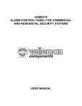
User Manual
1S DC-DC BOOSTER
HW-SM815DUL-20140320
Introduction
1S DC-DC BOOSTER is a DC-DC power booster module which can draw power
from the 1S Lipo battery then boosts it to the voltage level (6V) suits the
receiver & servo and provides the continuous output current up to 3Amp. It is
mainly applied in 1/12th scale RC vehicles.
The 1/12th scale car usually uses 1S Lipo battery, and BEC in ordinary speed
controller is step-down. In that case, the BEC output voltage will be lower than
4.2V that cannot meet the power demand of the receiver & servo.
Therefore, 1/12th scale car has to run with purpose-built 1S ESC with the built-in
DC-DC booster or external receiver battery connected if the speed controller
hasn’t the built-in DC-DC booster. However, things will be different after adopted
this booster. Then the receiver batteries can be abandoned and users can be free
from charging and maintaining the receiver batteries.
Specification
• Input Voltage: 1S Lipo or 3-4 Cell NiMH
• Output Voltage: 6V
• Output Current: Continuous 3A, Burst 6A
• Dimension: 28.0mm x 26.8mm x 11.8mm (L x W x H)
• Weight: 10.2g
Wiring Diagram
To Receiver
Connect to Battery
1. When the ESC (Electronic Speed Controller) has the built-in BEC function
Users need to cut off the internal BEC output first, that is to disconnect the red
wire between the speed controller and receiver (as shown in the picture below),
then connect the positive & negative poles of the input end of the 1S DC-DC
BOOSTER with the positive & negative poles of the battery and plug the output
end of the booster into any unoccupied channel of the receiver at last.
Recommendation:
Please use a little tapering screwdriver to remove
the red wire (in the middle) from the connector,
and insulate it well for future use. If want to restore
the built-in BEC function, you only need to reinsert
it into the slot.
2. When the ESC (Electronic Speed Controller) has no built-in BEC function
Then no need to make any change to the ESC except connecting the positive &
negative poles of the input end of the 1S DC-DC BOOSTER with the positive &
negative poles of the battery and insert the output end of the booster into any
unoccupied channel of the receiver.