1
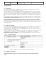
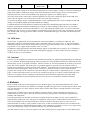
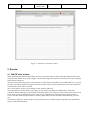
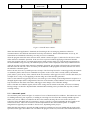
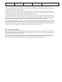
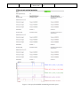
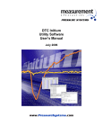
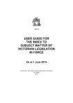
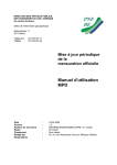
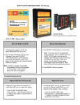
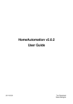
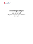
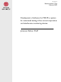
15 001 februari
Examensarbete 15 hp
Februari 2015
Development of software for MALTE, a system
for automated testing of line current supervision
and interference monitoring devices
Johannes Zeltner Wolff
Abstract
Development of software for MALTE, a system for
automated testing of line current supervision and
interference monitoring devices
Johannes Zeltner Wolff
Teknisk- naturvetenskaplig fakultet
UTH-enheten
Besöksadress:
Ångströmlaboratoriet
Lägerhyddsvägen 1
Hus 4, Plan 0
Postadress:
Box 536
751 21 Uppsala
Telefon:
018 – 471 30 03
Telefax:
018 – 471 30 00
The aim of the project is to develop software to automatically test line current
supervision and interference monitoring devices for Bombardier trains. The software,
called MALTE, it to replace the manual testing done by an engineer, thereby freeing
up the tester to do other tasks, and increasing the test rigorousness.
The test software, written in LabView, was developed in tandem with a hardware
rack, with interfaces to the train hardware enabling communication between the two,
to set test conditions and simulate the environment encountered by the hardware
when on the train.
When completed, MALTE was found to be an order of magnitude faster than a test
engineer performing the tests, meaning a large save in time and cost for the
engineering team.
Hemsida:
http://www.teknat.uu.se/student
Handledare: Fredrik Malmgren
Ämnesgranskare: Christoffer Karlsson
Examinator: Martin Sjödin
ISSN: 1401-5757, UPTEC F15 001
Table of contents!
1! Definitions*and*abbreviations*
2!
2! Introduction*
2.1! Background*
2.2! Integration*testing*
2.3! A*case*for*automation*
2.4! Project*description*
2.4.1! Project!goals!
3!
3!
3!
3!
4!
4!
3! Theory*
3.1! MALTE*hardware*
3.2! DCUHterm*
3.3! Labview*
4!
4!
5!
5!
4! Methods*
5!
5! Results*
5.1! MALTE*main*window*
5.1.1! Automatic!panel!
5.1.2! Manual!panel!
5.2! Instrument*interfaces*
5.3! Report*generation*
5.4! Test*case*structure*
5.5! Test*functions*library*
6!
6!
7!
8!
8!
8!
9!
11!
6! Discussion*and*conclusion*
6.1! MALTE*as*a*replacement*for*manual*testing*
6.2! Further*development*and*improvements*
6.3! Time*saving*analysis*
12!
12!
12!
12!
Language
Revision
Page
en
__ 2013-10-22
2
1 Definitions and abbreviations
AI
DCU-term
DI
DO
GPIB
LCB
LIM
MALTE
MVB
RS-232
RTS
R2N
VCU-C
Analogue input
Input ports on the LIM for measuring analogue signals.
Data communication user terminal
Application for communicating with train hardware.
Digital input
Input ports on the LIM for measuring digital signals.
Digital output
Output ports on the LIM for sending signals to other devices on train.
General purpose interface bus
Communications bus commonly used by measurement equipment.
Line circuit breaker
Circuit breaker separating the train from overhead power line or 3rd rail.
Line current protection and interference monitor
A device in the MITRAC product family of train control devices.
Manual and automatic LIM test equipment
A system for automated and manual testing of LIM hardware and software.
Multifunctional vehicle bus
Communications bus used for communication between devices on train.
Radio sector - 232
Serial communications protocol.
Real time simulator
Equipment for simulating a complete train propulsion control system.
Regio-2 Nord
Regional trains under development for SNCF in northern France.
Vehicle computer unit - communication
A device in the MITRAC product family of train control devices.
Language
Revision
Page
en
__ 2013-10-22
3
2 Introduction
2.1 Background
This document outlines the design of equipment to automatically perform integration tests of line circuit
protection and interference monitoring devices, or LIM’s.
The LIM is a hardware product of Bombardier Transportation installed on locomotives and electric multiple
units. Line circuit protection describes the LIMs role of protecting the catenary or third rail and transformer
against excessive voltages or currents. Interference monitoring describes the detection of small superimposed
currents or voltages on top of the line current, which might interfere with signalling equipment along the rail
line.[1]
If the LIM detects an unwanted signal, it will usually send a warning signal called a trip to other parts of the
propulsion system, usually resulting in the opening of the line circuit breaker, which will cut off the power to
the train from the over-head lines or third rail.
Each type of train has a different set of requirements on what to monitor, which parameters are acceptable,
and how the train should respond to deviations. The project specific features are controlled by a piece of
software called user window, and a separate parameter file sets the parameters. The user window works on top
of other software common for all train types called the core software, and code related to signal processing
called DSP software.
2.2 Integration testing
As new trains are developed, and during the first years of operation, the user window needs to be updated on a
frequent basis, because of changed requirements or found bugs. Before a new version of the software is
released it needs to be tested through a process called integration testing, where the new software is loaded to
a LIM and all software functions are tested.
This used to be done manually, after loading the software under test to a LIM in the test lab. The tests consists
of applying voltage or current signals to the analogue inputs and observing the response of the LIM by
watching the digital outputs or observing values of internal variables in the software or signals sent over the
Multifunctional Vehicle Bus, or MVB.[2]
Figure 1: Excerpt from a system integration test instructions document.
2.3 A case for automation
A complete integration test takes around 2 working days to perform, and sometimes the tests need to be
performed more than once, if any issues are discovered during testing which require additional software
changes.
Language
Revision
Page
en
__ 2013-10-22
4
The test instructions can sometime be vague, or incomplete, which can introduce differences in how the tests
are performed depending on the tester, and also leaves it up to the person doing the test to decide the degree of
documentation.
All these problems can be solved by automating the process. By the very nature of being automated, it frees
up the engineer to perform other tasks while the test is in progress. It also makes sure the tests are performed
the same way each time, and enables a standardised documentation that can include as much information as
available or wanted.
The standardised documentation also enables easier comparisons of different versions of the software,
allowing better traceability of old previously undiscovered bugs or comparing other unexpected behaviours
among software for different train types.
2.4 Project description
The aim of the project is to implement the software solutions necessary to fulfil the requirements below. This
means the possibility to create, save and edit sequences of test cases, and the implementation of all test cases
needed to replace manual testing.
As MALTE, Manual and Automatic LIM Test Equipment, will replace the manual testing, the reports
generated must be on the format, and good enough quality to be used directly as part of the release
documentation for the software package
In the event that a one time test needs to be performed for which no pre-programmed test case exist, a manual
control panel should be implemented as well, giving the user manual control over function generators and
relays.
2.4.1 Project goals
1. MALTE shall be capable of completely replacing the manual integration tests for the Regio-2 Nord
(R2N) project
2. A report capable of being included in the software release documentation shall be generated
automatically upon test completion
3. A control panel shall be present for manual control of all MALTE equipment
4. There shall be digital documentation of each Labview function and for the MALTE hardware
5. An analysis of time savings and payback time for spent development hours.
In addition to these over arching project gaols, the following implementation specifications must be met.
A. A function to control voltage output of the calibration unit must exist
B. Software to enable MVB communication to and from LIM via a serial connection to a Vehicle
Computer Unit – Communication device, or VCU-C for short.
C. The digital inputs shall be able to change state automatically by feedback from the digital outputs.
3 Theory
3.1 MALTE hardware
The MALTE equipment is mounted inside a 19’’ server rack, connected to a workstation from where the
equipment is controlled, and also has the software necessary to implement new test cases or functionalities.[3]
One can group the MALTE hardware into 4 different categories. Relay switch boxes, function generators,
digital multimeter and power and communications equipment.
MALTE has two function generators, one for high accuracies at very small currents, and one capable of
delivering high current or voltage amplitude. They share an overlapping area of operation where they for some
Language
Revision
Page
en
__ 2013-10-22
5
test scenarios work equally well. The function generators are used to apply a voltage or current to an analogue
input on the LIM, to simulate the output from a train mounted current or voltage sensor. If necessary, the
function generators can be used simultaneously, applying a signal to two different inputs.
The relay switch boxes connect the 2 function generators to any of the 8 analogue inputs of the LIM, and
makes sure the signal is sent to the AI port on the correct pin in the connector.
To measure the digital output, a digital multimeter is used, enabling MALTE to react to changes in DO and
change corresponding digital input (DI) feedback accordingly.
Communication between the different components in MALTE is handled through USB, RS-232, GPIB or
Ethernet, with hubs and adapters minimising the amount of cables running between the two. To facilitate
MVB communication, the LIM is connected to a VCU from which the signals can be accessed over RS-232.
In addition to this, a series of power supplies are installed to supply power to the relay switch boxes, the USBhub, and the LIM. The supply for the LIM is variable, as different trains types use LIMs with different power
requirements
3.2 DCU-term
DCU-term is an application used to communicate with train hardware, over Ethernet or RS-232. The
application consists of a terminal window where commands can be sent to the device. A list of all variables
within the program can be shown, from which one can set or read the variables value, or add the variable to a
log window, to see a graph of the variables value over time.[4]
In addition to applying stimuli to the LIMs analogue inputs, an important part of testing is to set variables to
trigger events or control the state of the LIM. Through the logging, it is also possible to measure timing of
events from 0.2s to several minutes.
3.3 Labview
Labview is a development environment from National instruments for graphical programming in the language
G. It is a dataflow programming language where programs are made up different functions connected by wires
drawn on the screen. A program in Labview, which is called a VI, for virtual instrument, is made up of a front
panel and a block diagram. The front panel is a graphical interface where the user can monitor values of
signals from indicators or control execution from controls.[5] Each indicator or control on the front panel has a
terminal on the block diagram, which is where execution is decided. In order to create an actual useful
program, the controls can be connected to operators doing for example math or signal analysis, for- or while
loops, or other subroutines known as sub-Vis; all visualised as objects on a canvas connected through wires.
Labview is a popular tool for working with measurement and automation equipment, and many major
instrument manufacturers proved interface libraries for Labview to communicate with their hardware.
4 Methods
Before coding could start, a full integration test for the R2N project was performed manually. The system
integration test specification was studied, to catalogue the different types of tests, and the steps involved. Each
step was also timed, so a direct analysis of time gains could be done when a working automatic test sequence
was first created.
The first part of coding was to create the launcher, shown in figure 2, from which the test sequences are
loaded and run. This in order to have the software framework to experiment with different integration test
modules and components.
From the point that it was possible to start the test engine and load an empty test case, work continued to
implement the simpler test cases with generic components. These generic components where then turned in to
sub-VIs and added to the test function library so that they could be reused for other test cases. For test
instructions that are used by a large number of test cases, or that are similar in function, the test function subVIs was combined into multifunctional test modules. This enabled the possibility to create a very large variety
of test cases using only a single test module, and only vary the input parameters.
This also made it easier to create test sequences for other train projects by copying those for the R2N project.
Language
Revision
Page
en
__ 2013-10-22
6
Figure 2: Automatic panel main window.
5 Results
5.1 MALTE main window
When launching the MALTE application, the user is presented with a window with three buttons and a series
of input fields, which can be seen in figure 3. Before choosing either manual or automatic panel, the 2 topmost
fields must be filled out.
The first field contains the project code, hardware revision and serial number for the LIM under test. To avoid
having to input these numbers by hand, a barcode scanner can be used to automatically enter this information
if the barcode on the LIM is scanned.
The second field is for the version number of the software under test.
This information is needed before proceeding, as each project has different LIM hardware with some
variations. When continuing to the manual or automatic panels, the software sets the relays in the relay switch
boxes to the correct configuration of pins to the correct configuration of analogue inputs. Each software
version also has different signal names or memory addressed to account for when communicating over RS232.
The last three fields are for the header of the generated report, to add the people responsible for the different
aspects of the documentation.
Language
Revision
Page
en
__ 2013-10-22
7
Figure 3: MALTE main window.
When the MALTE application is launched, the first thing it does is setting up parameters related to
communication to the different instruments and relay switch boxes. When communications are set up, all
instruments are initialized so that they are ready to receive commands.
Then the program enters the menu selector mode, which is shown in figure 3, and waits for the user to select
either manual or automatic operation. If the user tries to proceed without supplying a LIM serial number
string, the program will give a warning and return to menu selector mode. To verify that the program parses
the serial number string correctly, the identified project name will be displayed in the Project indicator field.
After the user has selected either manual or automatic operation, the program will load up the selected panel,
and then enter the run state, where it will stay for the duration of the program execution, until the user closes
the manual or automatic panel.
In the run state, there are 2 parallel processes in loops. The first loop listens for events triggered by the manual
or automatic panels, and executes commands in response to the events. This is mostly used by the manual
panel, where a press on any of the controls on the user interface will trigger an event to execute that action, for
example close a relay, or start applying a current using one of the function generators.
Some events cannot be triggered by the user. One such type is the change of DI configuration in response to a
changed digital output (DO) configuration. If the line circuit breaker (LCB) feedback is activated, the second
loop will measure the status of the DOs, and trigger a DO change event if the DOs change.
Some of the DIs are feedback signals, that if in the wrong state in relation to the DOs, will cause a LIM trip.
During testing it is therefore important that automated DI switching can be performed at any time, without
warning or delay.
5.1.1 Automatic panel
The automatic panel, shown in figure 2, consists of a row of buttons and 2 list windows. The buttons are used
for loading and saving test sequences, or adding or removing test cases from the currently loaded sequence.
When a test case is added, it is added to the lower list window showing all test cases in the current test
sequence, along with their path. If a sequence is saved, a text file is created containing the list of paths to all
involved test cases. These can in turn be read and imported back into the automatic panel. A complete
integration test typically uses around 15-20 test cases, depending on the project.
When the Start test button is pressed, the LIM is turned on, and the test cases are loaded and run in the order
specified. In the upper list window one can follow the progress of the test, where the same information that is
Language
Revision
Page
en
__ 2013-10-22
8
written to the report is displayed. This gives the possibility to detect a failed test and abort the execution
before the test sequence has run to its end.
5.1.2 Manual panel
The manual panel enables manual control over the function generators and the relay switch controls. The
panel also launches 2 DCU-term windows for direct communication with the LIM and the VCU-C, for manual
setting of signals or logging.
Figure 4: Manual panel window, with controls for DI and the function generators.
The DI control is a series of on-off switches to set the digital inputs to the LIM to on or off. If wanted and if
the LIMs project supports it, the LCB feedback can be activated, which can set the DI relays depending on the
measured DO configuration. The remote control is for turning the LIM on or off. Even if the LIM receives
power, it will not start up unless the remote digital input is set.
The function generator controls enable the user to set the amplitude and a frequency to apply to a chosen
analogue input on the LIM. Upon activation, the green border around the control turn orange, to notify the
user that a function generator is in operation.
5.2 Instrument interfaces
DCU-term comes with a pre-existing library of Labview code to enable communication with the LIM from
Labview. In order to simplify implementation, a library of common tasks was created, that could be used
throughout the MALTE application.[4]
This includes things like setting or getting signal values, adding signals to the log window or modifying a part
of memory in a specified location. The same library is used for MVB communication with the LIM, as the
MVB is accessed by setting or reading variables in the VCU-C over RS-232, which in turn communicates
with the LIM over MVB.
The function generators and the digital multimeters also came with extensive libraries to control their
functions from within Labview.
5.3 Report generation
An important part of MALTE is the generation of reports. As the tests are the final verification that a new
software version is operating as it should, and are judged through the results of a integration test report, it is
paramount that they are clear and encompassing enough.
Language
Revision
Page
en
__ 2013-10-22
9
As the report generation is automated it is now possible to include plots for all logged signals in the test
record, something which would require a lot of extra work on the part of the testing engineer, and often not
done unless the test specification asked.
In addition to the plots, a dump of the command history from DCU-term is automatically saved making it
possible to trace with good accuracy what happened during a test. This is especially important to find a reason
for a failed test, but also useful during development of new test cases.
As a general design direction, the new reports were using the same structure as the old test instructions and
reports. This can be seen in figure 5 which shows the new report style, and compare with the old one in figure
1. However, since they no longer need to be in a format that conveys test instructions to the test engineer,
there might be a better layout that more clearly presents the results in the best way possible.
There are pre-built libraries for Labview to interface with Excel, but they contain mostly low level functions,
like selecting cells and setting cell properties. To make report creation and formatting easier, a library with
report generation specific VIs were created. These include more specific functions, like inserting the test case
result to the report, or format the report section headers in a predetermined way.
.
5.4 Test case structure
When a test case has been loaded from the automatic panel, the first thing the test case has to do is to reserve
space in the report and to write the test case section header. The status of the test is also set to running in the
automatic panel test sequence list window.
If the user has requested an abort, the test case will wrap up and write an abort status to the report and then
close. If not, the test case will execute the actual test code. The test code for the test case Line current
overvoltage protection can be seen in figure 6, and the generated report section in figure 5.
Language
Revision
Page
en
__ 2013-10-22
10
Figure 5: Excerpt from MATLE automated generated report.
Language
Revision
Page
en
__ 2013-10-22
11
Figure 6: Code for test case Line current overvoltage protection.
The first VI to execute is the test function InitFastlog.vi, which adds the signals listen in the string constant
box to the fastlog in DCU-term. The second VI to execute is the test module TripTest.vi, which is a large
selection of test functions and can be programmed to do a large variety of tests depending on the input
structure wired to its input. The first columns in the cluster relate to parameters for the function generator, like
which AI to stimulate, amplitude unit and frequency (here for example 480 mA 0 Hz). The next columns
specify whether to perform different common tests. If an input field is preceded by a green true Boolean
constant, the test will be carried out. The first tests are checks for certain codes in trip messages one, two or
three; in this case trip message 1 shall be 0x10, message 2 and 3 shall be 0x0. The next part is for monitoring
the value of a signal during stimuli, and the last tree columns are for monitoring the fast Fourier transform of
the signal.
5.5 Test functions library
An extensive list of different test functions has been built to enable the creation of almost every part of the
integration test for any project.
Example of commonly used test functions can be seen in the table below
Test function
Purpose
Di4reset.vi
Sets DI4 to 1 and back to 0, thereby resetting a
LIM trip.
GetAE.vi
Reads list of warning messages generated from
User window.
GetSignal.vi
Returns value of specified signal from LIM
SetSystem.vi
Sets the LIM into different modes, usually if train
expects AC or DC power, or if railroad is icy.
LIMPowerOffOn.vi
Reboots LIM. Sometimes only way to restore
warnings and return LIM to normal operation.
Wait_ms.vi
Halts execution for specified time. Useful when
LIM reactions are not immediate.
Language
Revision
Page
en
__ 2013-10-22
12
6 Discussion and conclusion
6.1 MALTE as a replacement for manual testing
The MALTE system is in its current state capable to replace all manual tests for the R2N project carried out
on test bench. This accounts for all test cases but a handful which requires access to an RTS, a real-time
simulator used for testing hardware and software in an environment similar to a real train. These tests can be
automated, but as the MALTE is physically separated from the RTSs, the RTS test need to be carried out
separately.
In addition, some projects have one test case that requires the use of an oscilloscope, something that is not
included in MALTE.
With these exceptions, MALTE can provide all current integration test functionality. There are also many
possibilities to extend the testing to more complex cases.
The reports generated follow the same structure as the old test instructions, and are at least as detailed as the
old ones, thereby fulfilling all the requirements to be included as release documentation.
6.2 Further development and improvements
The existence of the manual control panel, voltage control of the function generators and automated LCB
feedback features makes the MALTE software meet all specified requirements for the project. However this
does not mean that more work could be done.
Using just a few additional test functions and corresponding test cases, it is possible to automate the parameter
file testing of the Do2010 and T2G projects as well, in addition to their integration tests. Parameter file testing
of other projects are already done automatically using equipment in Germany. If implemented, these tests
could be carried out in Västerås as well.
6.3 Time saving analysis
If summing all the measured times from the initial manual integration test, one gets a total of 3 hours 30
minutes. This can not be considered an accurate measure of how long time the tests take in total, as the time to
set up the experiments, or to interpret unclear test instructions are not included in this measure. It is found in
practice that it takes around 2 days to complete one integration test.
MALTE does the same test sequence in 59 minutes. This is not only a major improvement in time compared
to the manual testing. As the tests are automatic, the testing engineer is freed up for other tasks, while the tests
are running.
Using a total development time of around 600 hours, the time spent on developing the test equipment will be
saved for other tasks after 40 completed tests. As the number of releases per year varies depending on
development status of current projects and influx of new projects, it is hard to estimate how long time in years
this corresponds to. Using the 2 previous years as an estimate, the development time of MALTE will be paid
back after around 5 years, not counting the fact that the test engineer can perform other tasks while testing.
Language
Revision
Page
en
__ 2013-10-22
13
7 References
[1]
[2]
[3]
[4]
[5]
3EGM007200D0332_H LIM Hardware Specification.pdf
3EST000230-5525__ LIM R2N SITR.pdf
3EST000229-1497__Design Specification MALTE.docx
3EST 55-481_H Mitrac CC DCUTerm Product Description.pdf
LabView User Manual. Available: www.ni.com/pdf/manuals/ [2014-07-22]