1
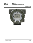
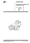
Heath Data Recorder HDR Series User’s Manual & Field Installation Guide Heath Consultants Incorporated Houston, TX 713-844-1300 Fax: 713-844-1309 1-800-HEATH-US www.heathus.com HDR Series HDR User’s Manual & Field Installation Guide Proprietary Notice The contents of this manual are proprietary to Heath Consultants Incorporated. Reproduction of this manual, in whole or in part, is prohibited without the express written consent of Heath Consultants Incorporated. Heath Consultants Incorporated operates under a continual product improvement program and reserves the right to make improvements and/or changes without prior notification. Purpose of this Manual The HDR is a powerful device that can be assembled and programmed in a variety of configurations. The purpose of this manual is to provide information for use in instrument shop setup and field installations. Models HDR Portable I.S. HDR Wall Mount I.S. HDR Pipe Mount I.S. HDR Portable HDR Wall Mount HDR Pipe Mount HPN 77R91-1001-1 HPN 77R91-1002-2 HPN 77R91-1003-3 HPN 77R91-1001 HPN 77R91-1002 HPN 77R91-1003 HPN 77R91-1070, rev C ©COPYRIGHT 2011-2015, Heath Consultants Incorporated 2 Table of Contents HDR I.S. Series (Purpose of this manual) ....................................................................................... 2 Table of Contents ............................................................................................................................ 3 Heath Data Recorder (HDR) Overview .......................................................................................... 4 HDR Features .................................................................................................................................. 5 HDR PCB Layout ............................................................................................................................ 6 Mounting & Installation .................................................................................................................. 7 Housing Configuration .................................................................................................................... 7 Pressure(s) Connection .................................................................................................................... 7 Temperature Probe(s) Installation ................................................................................................... 7 Electrical Installation ....................................................................................................................... 7 Battery Pack & Back-up Batteries................................................................................................... 8 External Power ................................................................................................................................ 8 External Modem .............................................................................................................................. 9 Internal Modem ............................................................................................................................. 10 Call-out upon Alarm wiring (when connected to Heath 2400 baud modem) ............................... 10 HDR Host Operating Software...................................................................................................... 11 Software Installation ............................................................................................................ 11-15 Quick Start Guide ..................................................................................................................... 15 HDR Configuration Detailed .................................................................................................... 16 User Friendly Names ................................................................................................................ 16 Site info and Instrument Modem .............................................................................................. 16 Pulse outputs ............................................................................................................................. 17 Alarm Configuration ................................................................................................................. 18 Alarms Reset using scroll button .............................................................................................. 18 Setting up “Call Out upon alarm” ............................................................................................. 18 Configure LCD sequence.......................................................................................................... 19 Configure Profiler ..................................................................................................................... 19 Watch Log................................................................................................................................. 20 Fast Log(s) ................................................................................................................................ 20 Set Real Time Clock ................................................................................................................. 20 Set Access Control (Security access passwords) ...................................................................... 21 Reset Instrument (Alarms/ logs etc.) ........................................................................................ 21 Auto Configure (saving/ restoring instrument CFG) ................................................................ 22 Adding a Transducer ..................................................................................................................... 22 Modbus Implementation................................................................................................................ 23 Downloading and Printing Data .................................................................................................... 23 Configuring for use with an IP Modem.................................................................................... 24-30 HDR Profiler Memory Capacity Table ......................................................................................... 31 HDR Firmware Update Procedure ........................................................................................... 32-35 Specifications ................................................................................................................................ 36 HDR Maintenance and Troubleshooting....................................................................................... 37 Periodic Maintenance/ Annual Checks ......................................................................................... 38 Maintenance Procedures (Calibration, Main Battery change & Backup/Restore Inst) ............ 39 Back-up Battery Replacement Procedure................................................................................. 40-41 Spare Parts and Accessories .......................................................................................................... 42 Service Information: Warranties and Warranty Repair ................................................................. 43 Configuration Worksheet .............................................................................................................. 44 Technical Support.......................................................................................................................... 45 3 Heath Data Recorder (HDR) Overview The HDR is a microprocessor based, self-contained system designed for the purpose of process monitoring using integral pressures and temperatures. Figures 1 illustrates the location of major components and user interface items. Temperature probe Ports 1 & 2 External Modem cable Port LCD Display 1 2 3 Pressure Ports 1, 2, 3 Scroll Button (on bottom) RS232 PC Comm. port Back-up Battery (under cover) Modem Battery (If equipped) Internal 2400 baud Modem (If equipped) Primary Battery Primary Battery Connector External Power Connector Earth Ground Stud (on bottom) Figure 1: General configuration of the HDR 4 HDR Features • Handles up to three pressures (3) and two (2) temperatures (plus ambient). • Intrinsically safe: Class I Div I Group D (without internal modem). • Measures, records & alarms on all connected sensors every second. • Single Alkaline “D” battery provides power for up to 4 years. • Single Lithium “AA” Backup battery will provide 100% operation for up to 1 year after main battery is depleted. • Wall mount, Pipe mount and Portable configuration options. • Continuous LCD displays all inputs (selectable with scroll button): up to three pressures, two temps, ambient temp, Main battery voltage, B/U Lithium battery voltage and active alarms. These readings are updated every second. • 16 fully customizable alarms with logging of time and readings at the time of trip & reset on all selected alarms. • Active alarms can be configured to blink the LCD reading every second. Scroll LCD to read the active alarm. • Alarms can be configured to reset automatically or manually. • Alarm Log (Records Alarm timestamps- Set & Reset). • Delta alarms can identify and record spikes in the readings every second. • Alarm call out to pager or phone (up to 3 phone numbers) upon any or all alarms. • Profiler data recording (up to 20 items)/ Circular log: Selectable intervals: (1 min/ 5 min/ 10 min/ 15 min/ 30 min/ 60 min). Time/ Ave/Min/Max- Pressures 1 & 2 & 3 (If equipped)/ Ave/Min/Max- Gas Temperature 1 & 2 (if equipped) & Ave/Min/Max ambient temp/ Main battery voltage & pulse inputs. • Profiler selectable memory size (50,400 up to 403,200). • “Fast logs”- (3) independent, high resolution event capture logs records and captures pressure data every second (High, Low or Delta, selectable) for one hour total (30 minutes before the trip point and 30 minutes after). • “Watch log”- provides an additional high resolution circular pressure data log. Recording options are: logging data every second for 9 hours of memory storage or averaging 2 second data for 18 hours or 4 second ave. for 36 hours or 8 second ave. for 72 hours (3 days) or 16 second ave. for 144 hours (6 days) and generates an Excel file automatically when viewed. • Config Log (Records configuration changes made to the instrument). • Remote Communications Ready (External Direct port & Internal Remote RS232’s). • Multi-Drop ready- Connect remotely to several instruments from one modem (Up to 62). • Protocols included: Sandia (Native)/ Modbus ASCII (RTU available in a future release). • PDC (Portable Data Collector) can download & store up to 166 full profilers. No PC needed to get field data. • Units of measure (PSIG, Ozsi G, H2O G, kPa G or Bar G, Deg. F/ Deg. C). • Pressure ranges (shown as PSIG): 1, 3, 6, 15, 30, 60, 100, 150, 300, 500, 1000, 2000, 3000, 5000 • HDR firmware can be upgraded via PC. • Non-volatile Flash memory saves Calibration, Transducer Coefficients, Configuration & Site info if all power is lost. • Housing is IP64, Aluminum, Powder coated paint over chromate surface prep, lockable stainless steel hasp closure. • HDR Host is compatible with Windows 8, Windows 7, Win Vista and Win XP. • HDR Host is very user friendly software for configuration, calibration and data processing. • Single PC Board design simplifies cabling and setup. • Compact packaging for easy transport and installation. 5 PRESS 1 J6 J5 J7 WIRED TO DISPLAY BUTTON JP5* 123 DATA MEMORY BATTERY BACKUP J2 GND GAS TEMP PROBE #1 PRESS 2 P1 +E P1 +S P1 -E P1 -S GND J10 PRESS 3 P2 +E P2 +S P2 -E P2 -S GND J11 DIRECT COM 1 P3 +E P3 +S P3 -E P3 -S GND J14 PULSE OUT B GND PULSE OUT A GND GND PULSE INPUT J13 MODEM COM 2 GND TXD RXD CTS RTS CD TXM RXM GND HDR PCB LAYOUT J9 GAS TEMP PROBE #2 GND GAS TEMP 2 J8 ASSY#: 77R65-9320 REV F GND INDEX B STOBE INDEX A STOBE 3V SYS 3V CR2032 INDEX INPUT (HVC ONLY) J12 BACKUP BATTERY 3.6V "AA" Lithium JP1* OPEN 1.5VDC GND MAIN BATT CONN J1 12VDC GND J11 12VDC EXT CONN NOTE: External connections to the pcboard should be made by acquiring locking harnesses for Modem connections (J13) and External 12V power (J11), Pulse input (J14) & (2) Pulse outputs (J10). Contact Heath Consultants customer service to get these harnesses. * JP1: This jumper switches the lithium power from the pcboard circuit. * JP5: When using the internal 2400 baud modem, a special harness is required for “Call out upon alarm” feature. This harness connects Pin 2 of JP5 to Pin 6 of J13 (External modems that stay online 100% doesn’t require this option). 6 Mounting & Installation Housing Configuration The HDR is available in many configurations. The maximum number of integral sensors is as follows: • • Pressure: up to three Temperature probes: two (plus internal case temp) The housing type will determine whether sensor connections are made from the bottom or rear of the instrument as follows: • • • Wall/Panel mount: bottom connect 2” pipe mount: bottom connect Portable: rear connect Pressure Connection(s) Connect up to 3 pressure inputs to the 1/4” NPT female connectors located on the bottom or back of the HDR housing. After piping is complete, check all connections to ensure that no leaks are present. Temperature Probe(s) Installation If equipped, up to 2 standard 6 foot long temperature probes (6” x 1/4” OD) may be used, and should be installed into the appropriately sized thermowell filled with a thermo conductive medium such as glycol or alcohol. Insert the temperature probes into the thermowells through the standard 1/4” inch NPT male gland (provided) until the tip of the probe reaches the bottom of the well. Secure excess armor cable length of the probe. It will be necessary to isolate the pressure and temperature connections to the pipeline, so as not to disturb the cathodic protection system. Electrical Installation NOTE: Refer to drawing MTM-308-1 for field wiring requirements for external power and modem connections to maintain intrinsic safety. The HDR unit must be earth grounded to maintain safe operation and warranty. The ground stud of the HDR (located on the bottom of the instrument) must be connected to a suitable known external earth ground (usually a dedicated ground rod and NOT AC ground). All of the major components in the HDR are bonded together and connected internally to this groundnut. It is required that grounding be performed, especially when an external modem and/or external power supply (which requires a dedicated ground rod in close proximity to the safe area) is used. All cabling connecting to the HDR must be shielded with all shields tied to case ground. For multiple device interconnections (modems, power supplies etc.) the groundnut of the HDR must be tied directly to this same (safe area) ground rod rather than having a separate ground rod of its own. The American Gas Association recommends grounding all electronic field devices to a driven ground rod. This will help protect the device from transients including lightning and power surges on the pipeline. To reduce the possibility of “secondary” lightning strike damage (damage caused by static electricity fields in the immediate area), the above precautions are required. However, these precautions cannot prevent damage to an instrument that receives a “direct” lightning strike. 7 Battery Pack and Back-up Batteries The HDR units utilize (1) 1.5-volt, encapsulated “D” cell alkaline battery as its primary power source. The pack supplied with the HDR consists of an alkaline dry cell and a protection circuit. (Part number(s) on page 42) NOTE: This battery is not rechargeable. HDR units are shipped from the factory powered and ready to install in the field (unless otherwise specified). The HDR incorporates an on board uninterruptible power supply. This consists of one factory installed “AA” lithium cell (BT1) rated at 3.6 volts. This cell is easily replaced in the field. The HDR incorporates an on board battery (CR2032) for backup of the profiler log. This consists of a replaceable button style lithium battery (BT2) located on the component side of the PCB. Normal battery voltage should be displayed between the ranges of 1.2 to 1.5 volts for a new battery, and when the primary power drops below .8 volts, the unit will switch to lithium backup. Under normal conditions, the main battery pack should last up to four years and the lithium backup battery should last up to 1 year without power from the main battery. Caution: When the communication cable is connected to the instrument, higher than normal battery current is consumed. Because of this, it’s recommended to limit the time connected to the instrument. Caution: The maximum voltage allowed on the “Main battery” input is 2 volts DC. Only use the 1.5 volt battery pack supplied by Heath. If this voltage is exceeded, a protection fuse will blow and the warranty will be voided. Note: If all three batteries lose power, the data that is stored in non-volatile memory will not be lost. This includes Calibration, Poly (transducer) and configuration data. Caution: To maintain the Intrinsic Safe rating, use only proper replacement batteries: main battery pack HPN 77R911037, Lithium backup battery, HPN 77R65-8001, and coin battery, HPN 77R65-8002. Contact Heath Consultants Incorporated for replacement batteries and main battery packs. Refer to Periodic Maintenance on pages 38-42 for replacement procedures & part numbers. External Power The HDR can be connected to an external power source (6- 15VDC). This connection is required when an external modem is used due to the RS232 load on the instrument. A wiring harness is required to connect the external power to the 12 volt source. Note: Contact Heath Consultants Incorporated to get this harness. 8 External Modem The HDR is equipped with two RS232 communication ports. The Direct Port is dedicated to local direct PC communication at 19200 baud using the HDR com cable. The Remote Port is used for connecting a modem. Remote baud rates available are 300, 1200, 2400 (default), 4800, 9600 and 19200. When configuring for a remote modem, the “Remote Modem Baud Rate” in the unit must match the baud rate of the field modem being used. Connect the RX, TX & GND from the modem to the instrument on J13. A wiring harness is required for this connection. Note: For proper remote communication using the native protocol Sandia, the modem [default] mode needs to remain. Modbus mode must be set to “RTU” & “Parity” must be set to “None”. Note: If the external modem powers down to save power, the CTS wire is required to wake the modem prior to “dialing out upon alarm”- if this feature is enabled. Otherwise the CTS wire isn’t required for inbound communication. Caution: When connecting the HDR to an external modem, it is recommended to connect external power to the instrument due to higher current demand. CTS Splice (Only required for modems that power down) Splice RX Splice GND Splice CTS RTS CD TXM RXM GND GND (Pin 5) RX (Pin 2) TX (Pin 3) DSR (Pin 6) TX J13 JP5 WIRED TO DISPLAY BUTTON 123 Modem Wakeup Jumper Wire 9 Pin GND GAS TEMP 2 RS-232 (Only required for modems that power down) 12V GND Non-Heath Modem ASSY#: 77R65-9320 REV F GND INDEX B STOBE INDEX A STOBE 3V SYS 3V CR2032 + - BACKUP BATTERY JP1 3.6V "AA" Lithium 12VDC Modem Battery OPEN 1.5VDC GND 12VDC GND 12V GND External power is recommended When connected to external modems. 9 Internal Modem The HDR may be equipped with an internal modem and phone line surge suppressor. The modem is pre-configured and pre-wired from the factory, ready for remote communication. If the HDR is equipped with the phone line suppressor, it will be connected directly into the modem’s RJ-11 connector. A 12-volt battery pack (8 “AA” batteries) is supplied, but not connected when shipped. The user must connect prior to remote communication. Assuming one two-minute call per day, every day, the battery should provide approximately 2 years of service. To connect a phone line to the modem, insert the phone cable through the wire gland into the case (see Figure 1). The cable must be terminated with a RJ-11 connector. Plug into surge protector if provided; else plug directly to the modem. The optional phone line surge suppressor will sacrifice itself to protect the equipment in the event of a destructive power surge on the phone line. Caution: Unit must be connected to proper ground to allow the surge suppressor to operate properly. Caution: Internal modem option is not currently certified for use in hazardous environments. An external modem should be used when necessary. Refer to drawing MTM-308-1 for field wiring requirements on external power and modem connections to maintain intrinsic safety. Internal Modem Wiring (with “Call out upon Alarm”) Yellow (CTS) (Wake-up wire for "Call Out Upon Alarm") Blue (TXM) Gray (RXM) CTS RTS CD TXM RXM GND Red (GND) J13 JP5 WIRED TO DISPLAY BUTTON 123 *Jumper wire Heath 2400 Baud Modem GND GAS TEMP 2 (Wake-up wire for "Call Out Upon Alarm") GND INDEX B STOBE INDEX A STOBE 3V SYS JP1* OPEN 1.5VDC GND Surge Protector (Optional) Phone Line BACKUP BATTERY 3.6V "AA" Lithium 12V Modem Battery 3V CR2032 Phone Line ASSY#: 77R65-9320 REV F 12VDC GND Connect the RX, TX, GND & CTS wires from the HDR to the modem using the modem harness required (contact Heath Consultants Inc for this harness). Plug in the jumper wire to JP5. Note 1: For “Call out upon alarm” feature. The modem harness connects Pin 2 of JP5 to Pin 6 of J13 (Modems that stay online 100% doesn’t require this jumper). Note 2: If the “Analog Modem” is NOT selected, the calls will be dialed 2 minutes apart. However, if the “Analog Modem” is checked, the calls will be completed ASAP (Approximately 20 seconds). Note 3: A “Manual” alarm must be reset in order to get a second “Call out” alert. An “Auto” alarm will call out multiple times if the trip points are exceeded in succession. 10 HDR Host Operating Software HDR Host is the companion software interface to the HDR instrument. The application program provides for configuration, calibration, local and remote communication, interrogation, data collection and data processing. The program is supplied on CD ROM media. The self expanding executable “setup” file will guide the user through the installation process. This install will work in Windows operating systems for Win XP, Win Vista, Win 7 & Win 8. NOTE: HDR Host must be on each workstation, in a network, that utilizes it. The data can be sent to a network drive and be shared by other workstations that have HDR Host installed. Remember to change the “Data Paths” of each workstation to use the same network drive and directory. DO NOT INSTALL THIS SOFTWARE DIRECTLY ONTO THE NETWORK SERVER DRIVE. Software Installation To install, locate the file “HDR Host Setup4.02.EXE”. Double-click the file to install. Follow the instructions to complete the installation process. After the software is installed, you may need to configure the com port to directly connect to the instrument. Com 1 is very common; however, many newer computers are not equipped with a 9-pin connector for direct connect with the standard com cable. A “USB to Serial adapter” may be required. Follow the instructions included with the USB to serial adapter. After the adapter is installed and connected to the PC, go to “Start”/ Control Panel/ System/ Hardware/ Device Manager/ “Ports” (click the “+” to the left of “ports”) Look for “ATEN USB to Serial Bridge (com xx)” Enter this port number in the HDR Host (Host Setup/ Configure Host)/ “Direct”. Any port from 1-255 can be chosen. Note: Only the available ports will be listed in HDR Host/ Host setup “Name” dropdown. NOTE: HDR Host requires a screen setting of at least 800 X 600. The bottom of the window may sometimes be out of view. Click “Next” to continue. 11 Accept the agreement. Then click “Next” to continue. Click “Next” to continue or change the default location of the HDR Host data files. 12 Click “Next” to continue or change the default location of the data log files. Click “Next” to continue or change the default location of the HDR Host shortcut. 13 Select additional icons. Click “Next” to continue. Click “Next” to continue installation. 14 Click “Finish” to complete the installation. Select the box to view the “README.TXT” file. Quick Start Guide 1. Run “HDR Host Setup 4.02.exe” to install the HDR Host software from the CD software disk provided. 2. After first time running of the software- message: Verify PC time is correct (“Check” to remove if needed or leave to remind). a. Setup “Host Setup” (Com 1, 19200, Direct, is most common). If your com port is different than com 1 (or you are using a USB to serial adapter, find out the port number and select it). Make sure to use the same USB port every time. b. Click “OK” to save the Host Setup. 3. Connect the communication cable from the PC to the instrument. 4. Using the HDR Host software, Select “Display/ Display1 Live Readings” to confirm connection. 5. Optional: To set up device naming conventions or enable devices: Select “Configure/ User friendly names”. Customize the names and enable devices as appropriate. (If no names are chosen, default values will be used). 6. To customize site information: Select "Configure/ Site Info" and enter site address in lines 1 – 3. 7. Initialize the “Profiler” to record pressures, temperatures, battery voltage etc. over time. Select: “Configure/ profiler", then select the items you wish to record from, and select the record interval from 1 to 60 minutes. To maximize the data storage time, select longer record intervals and the least record types necessary. Select smaller record intervals for short term but very detailed data. 8. Configure the following as desired: Set up the alarms – Configure/ Alarms; Configure Fast logs: Configure/ Fast logs. To configure the Watch log go to: Configure/ Watch log. 9. To retrieve data or directly print a report: Select “Data”, and then select the desired download or report to view or print (Download: Profiler, Alarm log, IOR Snapshot, Configuration Log, Modem Error Log) (Print: Profiler, Print Alarm log, Print IOR Snapshot, Print Configuration Log, Print Modem Error Log or View Saved Fast Logs). 15 HDR Configuration- Detailed User Friendly Names (Allows custom channel names of active channels- when required) 1. Go to the Configure Column/ “User Friendly Names” 2. Click the check-box next to the channel to add or type a custom name for the channel. Note: This custom name will follow the channel throughout the software & reports. Site info and Instrument Modem 1. Enter Site Address info. Note: Site address line #1 will be used to create filenames for downloaded reports. 2. Set baud rate to match the remote modem (if connected). 3. “Analog Modem” checkbox affects the time between dialing out to “Call out upon alarm”. Unchecked will cause the three calls to be 2 mins apart (recommended for cellular modems to give the modem time to properly dial all three calls). Checked will cause calls to go out ASAP (best used with land-line modems because they can dial all three calls fast). 4. Set up Modbus here (Parity & Modbus mode: ASCII or RTU. RTU not active at this time). Note: “The Schedule Reporting via E-mail”, “Alarm Notification via E-Mail” & “Access Telephone numbers” isn’t active at this time (See below). #1 #2 #3 #4 These three features aren’t active at this time Call out to pager/ phone feature configuration. 16 Pulse outputs 1. The HDR has two pulse outputs that can be independently configured for Alarm closure (for external visual or audible alert or to notify another device of the alarm) or pulse repeating. To set up the pulse outputs for alarm pulse closure: a. Go to the Configure column. b. Select “Configure user friendly names”. c. Select the pulse output to activate, click “OK”. d. Then go to the configure column/ “Configure Pulse I/O and 4-20 Ma Sender”. e. In the “Pulse Outputs” area, click under “Use”, select “Alarm” to create a contact closure upon alarm. f. Select “Pulse” to allow pulses to be sent (when input pulses are configured). Note: The “Force On”= Contact closed. “Force Off”= Contact open. “Short On”= Can be used to control a motorized regulator for remote pressure control. 2. To set up the pulse outputs for remote pressure control: a. Go to the configure column/ “Configure Pulse I/O and 4-20 Ma Sender”. b. In the “Pulse Outputs” area, click under “Use”, select “Short On” c. In the “Momentary” area, enter the number of seconds to keep the pulse output closed (when the “Pulse output button” is clicked on the Display 1 screen). d. To set up the button on Display 1, go to “Configure column”/ “Configure User Friendly names”, click Pulse Output 1 (for pulse 1) &/or Pulse Output 2 (for pulse 2). Enter a custom name if necessary (Example: “Increase”/ “Decrease” or “Up”/ “Down”). Note: After setting up pulse outputs for controlling a closure, Go to “Display 1” and click one of the four buttons at the bottom of the screen. During the pulse closure, a scroll bar will appear displaying the progress of the closure. After clicking “Pulse output 1” a scroll bar appears for 5 seconds during the “Closure”. Configuring Pulse outputs for 5 second closure. 17 Alarms Configuration (set up to 16 alarms as necessary): 1. 2. 3. 4. 5. 6. 7. 8. 9. 10. Click the box next to the alarm to activate Type the “Name” of the alarm to configure (use any name to describe this alarm). Select the “Point” (P1,P2,P3,T1,T2,Case Temp, Batt Volt, Lith volt) to monitor. Select “H/L” (Lo, Hi, Dlt). Lo= Low pressure alarm/ Hi= High press alarm/ Dlt= Delta (difference from one read to another in a 1 second period either high or low). Select the “Mode” (Auto/Manual). This is the alarm “reset”. If set to “Auto”, the alarm will reset automatically. If set to “Manual”, the alarm must be reset by holding the pushbutton for 4 seconds or from the host software: Config column/ Reset instrument/ click “Reset all active alarms”, click “OK”. Set the “Set Val” to the value that will trip the alarm. Set the “Reset Val” to the value that will reset the alarm. This value must be set higher than the trip point on the low alarms and must be set lower than the trip point on the high alarms. The software will show a warning if this isn’t correct: “Alarm Set/Reset Value Error Entered/ Please correct entries””. “Logging” is for logging the alarms on set &/or reset, options include: “None” (all alarms will not be logged- set & reset). “Set” will log the time & date only the alarms that are tripped. “Reset” will log the time & date of the alarms that are reset. “Both” will log the time & date of all alarms when tripped and reset. “Pls Out” will allow a contact closure on one of the pulse outputs to allow a light or buzzer to better to alert the active alarm. Note: The pulse outputs need to be configured to use: “Alarm”. “Calling”- click to allow the instrument to “Call out upon alarm”. Click “Call pager” and enter a “Pager Display” number that would display on the pager. Note: If no pager is used, (use a landline or cell number) the phone will ring and the “Pager Display” tones will beep in your ear during the call. Note: “Call Host” and “Send E-Mail” isn’t active at this time. Alarms Reset Using Scroll Button All active alarms can be reset manually by holding the scroll button closed for more than 4 seconds. They can also be configured and reset by using the HDR Host. An active alarm will be indicated by the LCD display “flashing” once per second. If the alarm mode is set to “Auto” and the alarm condition is resolved, the alarm will reset automatically. The alarm “Set” and “Reset” date/time stamp will be recorded in the Alarm log (when “logging” is set to “Both” in alarm configuration). Setting up “Call out upon alarm” (Call pager, land-line or cell phone): a. From the “Configure Alarms” screen, select “Calling”. Click “Call Pager” and enter any number in the “Pager Display” area. b. From the “Configure Site info” screen, enter up to three phone numbers (Pager 1,2, or 3) that the instrument will be calling (same number three times, three different numbers or any combination of numbers up to three). c. “Pager Delay” will set the delay time from the end of dialing the phone number to the time the “Pager Display” number will be sent to the pager. Test call the pager number and time how long it takes to enter the “Pager Display” number. If dialing strait to a cell phone (or landline phone), the “Pager Display” value doesn’t matter. 18 Configure LCD sequence 1. Go to the configure column/ “LCD Display Sequence”. Select the items to be viewed on the HDR LCD screen. Leave any items un-checked to hide them from the LCD. In the example below, if “Low Press 1” alarm was active, the low pressure alarm would not be visible on the LCD (because it’s unchecked) but will show in the software. The HDR has 3 types of data logs: 1. Profiler: (Core log) is programmable from 1 min up till 60 min interval. Channels are selectable (Ave/Min/Max) Pressure 1, 2 & 3/ Temp 1 & 2/ Case Temperature & Battery voltage). This log is capable of storing large amounts of data. This log is circular- first data in last data out. To save this file go to “Data”/ Select Downloads/ Check off “Profiler”/ Click “OK”). a. To configure the Profiler, go to Configure Column/ “Profiler” b. Select each field to be recorded in the Profiler c. Select the desired “interval in minutes” (1 min/ 5 min/ 10 min/ 15 min/ 30 min/ 60 minutes). Note: The more often the interval, the less memory available in the HDR storage (as seen in the “Total size in days”). Note: See the Profiler Memory Capacity table on page 31 to determine the best configuration for your requirements. Memory size will be displayed here 19 2. Watch log: Records 1 pressure channel (High resolution log selectable from 1 second data, for 9 hours data storage, up to 16 second averaged data to provide 6 days of stored data). This log is circular- first data in last data out. To save this data go to “Display column”/ “View Watchlog”/ Select the timeframe & start time, click OK. The data will appear automatically in Excel. This is probably the best log to use for leak testing. 3. Fast log (X3): Three separate logs recording #1, #2 or #3 pressure channels only (or any combination: Low, High or Delta (“Delta” will record a specific pressure spike or drop within a 1 second interval). These three independent logs “Capture” the event with a trip point (similar to an alarm). This log records data every second for a total of 1 hour. After the trip point is reached, the data recording will continue for 30 more minutes and stop. There are 3 modes: 1. “Running” (continuously recording data points- waiting for a trip point), 2. “Pending” (Trip point has been reached but waiting to finish recording the rest of the 30 minute data, 3. “Stopped” (The trip point has been reached and 30 minutes has passed). After these logs have stopped, they can only be reset using the Fastlog reset- “Configure column”/ Reset Instrument/ Reset Fast Log 1/2/3. The Fastlog data can be saved in a Binary file (Graphical format) that allows zooming in or out on the pressure trend line as well as Min, Max & Average readings. This data can also be saved in a “CSV” format to view in Excel. Set Real Time Clock 1. Go to the Configure Column/ “Set Real Time Clock”, click “OK”. The window that appears on the screen is comparing the “Host Standard Time” to the “Instrument’s Standard Time”. Click “OK” or type <enter>. This will set the instrument time-clock to match the computer’s clock. PC time HDR time 20 Note: The instrument doesn’t adjust for Daylight Savings time. Setting the HDR clock uses the computer’s time-clock it’s connected to. Set Access Control (This sets the security passwords of the instrument) 1. In HDR Host, Go to the Configure Column/ “Set Access Control” in the instrument. Note: “logon” and “readonly” are the instrument’s defaulted passwords. These can be changed to be more secure. 2. The “Host Setup” screen (See below) allows setting up the password in the computer. When the “Host” password matches the “instrument” password, access is granted & no password will be prompted. If these don’t match, a password window will be prompted. Note: This password will typically be the same for all devices so that one password entered in all instruments and all technicians’ laptops will allow password free access to any instrument in the system. 3. To use the “Readonly” mode: Set the HDR Host/ Host setup “Default Logon Password” to “readonly”. This will allow a user to see data but not change any configuration or calibrate (Config & Calibration columns are removed). Reset Instrument (Allows resetting: All Alarms, Fast loggers 1,2,3, Profiler, Fault log (Clearing the Fault log also clears an instrument Fault) , Configuration log, Pulse inputs & outputs, watchlog or “All the above”. All stored data will be erased. Go to: “Configure” column/ “Reset Instrument”/ select what to be reset in the instrument. Note: This option will NOT erase the HDR firmware, Configuration, Transducer Coefficients or Site Info. Erasing the profiler WILL erase the stored data file in the HDR. Use this feature while setting up a new unit. 21 Auto Configure (Allows saving and sending the Configuration, Calibration, Transducer Poly & site info) 1. To Save this file a. Go to "Configure column/ Auto Configure/ & click: “Save Inst Config, Cal & Polys" b. Click “Save” Or type a custom filename & click “Save”. 2. To send (restore) this file to the instrument: a. Go to "Configure column/ Auto Configure/ “Send Config, Cal & Polys to Inst" b. Select the configuration file: Example: "325012345.cfg" c. Choose what to restore from the list (1,2 & 3 Calibration, 1,2 & 3 Poly, Temp probe 1&2 Calibration, Battery voltage & Lithium calibration, Site info, User Friendly Names/ Equipped Flags, Alarm Configuration, Profiler Configuration & General Configuration). Or click the “Select All” button. d. Then go to "Display 1" and make sure this unit is configured for your specific application. Note: Make sure not to send the calibration data from a different unit. Select-> Or Select All Then click OK Adding a Transducer (Additional pressure transducer(s) can be added- up to 3 total) Ranges available: 1, 3, 6, 15, 30, 60, 100, 150, 300, 500, 1000, 2000, 3000, 5000 (all ranges are PSIG but can be converted to other units of measure). To convert the Units of Measure, change the “Full Scale” in the “Calibrate” column/ “Edit Calibration terms”/Pressure 1, 2, or 3 . Example: 1 PSIG converts to 16 OzsiG (Full Scale=16). Example #2: 1 PSIG converts to 27.68 InH2O (Full Scale=27.68). Then change the “Units of Measure” in this same window. 1. 2. 3. 4. 5. 6. 7. 8. 9. Physically install the transducer into the bulkhead using the proper thread tape. Remove the main pcboard cover-plate (Remove the (4) nuts on the corners of the pcboard). Plug the transducer into the appropriate connector for the pressure channel to be added (See page 6 for pcb layout). Go to Configure column/ User Friendly names/ & click: the next available pressure channel, type in a custom name for this channel (if required). Go to Calibrate column/ Import Poly/ & click: Import poly for the pressure channel that will be added (call Heath Consultants to get this transducer “Poly” file). Go to the “Calibrate” column/ “Calibration Wizard”, select the 2-point pressure channel added to be calibrated Click “Begin” and follow the instructions to complete the calibration. Make sure to click the “Save” button first, and then click the “Finished” button. Go to “Display 4” to confirm the calibration date-stamp has been updated. 22 Modbus Implementation 1. Modbus can be used as long as it is ACSII (Modbus RTU is not currently active) Packet framing: Data bits=7 / Parity= Even/Odd/None / Stop bit=1. Note 1: After setting Modbus to ASCII, the remote port will not work using the Native protocol Sandia. Note 2: The direct port will always work with Sandia protocol (native). 2. Set up Modbus in the “Configure” column/ “Site Info” a. Baud rate should match the baud rate of the modem connected to the remote port of the instrument. b. Parity: Even/ Odd/ None. Select this option for Modbus. c. Modbus address: Default is “001” Use this for multi-dropping more than one unit to the same modem (Range= 001- 255) d. Modbus Mode: ASCII / RTU. Select the type of Modbus required (RTU is not active at this time). Note: Contact Heath Tech support for the Modbus address map DOWNLOADING AND PRINTING DATA To download data follow the steps below: 1. 2. 3. 4. 5. Run the HDR Host software. Go to the “Data” column & click “Select Downloads” Select the reports to download (or click the “select all” button). (Optional) Enter custom filename all reports will use. Click “OK” button to save files. To print Profiler data follow the steps below: 1. 2. 3. 4. 5. 6. Run the HDR Host software. Go to the “Data” column/ Choose “Print Profiler”. Select the report to print: “High Granularity” “Daily” or “Monthly”. Choose the filename of file to report. Choose the date & time span to report on the calendars. Select “Send output to”: a. Console (creates text file and displays the file on your screen. This file can be saved). b. Printer (prints report on the printer that is attached to the computer). c. File (must type a filename for a text document that will be created. Example: Monthly.doc). d. Spreadsheet (selected data will be displayed in Excel automatically) To print IOR (Instrument Operational Report) data follow the steps below: 1. 2. 3. 4. 5. 6. Run the HDR Host software. Go to the “Data” column. Select the report to print: “Print IOR Snapshot”. Choose the filename of file to report. Choose the time span to report on the calendars or choose “Last Report”. Select “Send output to”: a. Console (creates text file and you can view the file on your screen). b. Printer (prints report on the printer that is attached to the computer). 23 Configuring for use with an IP modem 1. Select “Host Setup – Configure Host”. 2. Click the “Network” Port Selection and then click “OK”. 24 3. Select “Comm – Master Directory”. 4. Click on the “New IP Addr” button. 25 5. Enter the IP address, Port Number and choose a Name/Location for the installation. In the COM Selection drop-down box, click on “Select 4 – TCP/IP” and then click “OK”. Click “OK” back on the Master Dialing Directory window to accept the information. The screen shown below is an example using the Heath engineering HDR instrument. 6. To begin using the IP modem it must be wired correctly, configured properly and powered up. The HDR modem port baud rate must match the IP modem baud rate. Refer to the IP modem manufacturer’s users manual for further information on its use and configuration. Heath provided IP modems will be pre-configured at the factory. 7. Select “Comm – Network – Start Session” to begin a network session. 26 8. Double-click the IP modem’s site name or single click the site name and then click “OK”. Editing is also available with this screen if needed. 9. While connecting to the IP modem a status window will appear. The IP address and Port shown below are an example only. The actual values will differ. 27 10. Once connected, the Host screen will indicate the connected IP address in yellow at the bottom of the window. 11. Select “Security – Logon Instrument” to logon to the remote HDR. When successful, “Logged ON” will be indicated in green at the bottom of the window. NOTE: Please be patient while logging onto the remote HDR. It can take several seconds to logon due to network traffic and delays. 28 12. To illustrate remote IP modem communication, select “Display – Display 1 Live Readings”. 13. The Live Readings window will appear after the data has been gathered and communicated. Note: This screen updates each second. 29 14. Remote HDR IP modem communications are available for use using the HDR Host. When finished, exit remote IP modem communications by selecting “Comm – Network – End Session”. The remote HDR will be logged off and the network session will end. #1 #2 #3 30 HDR 325 Profiler Memory Capacity Table Example: 10 min recording of 4 fields yields 350 days of Profiler data stored in the HDR The Profiler is selectable from 1 min. up to 60 mins & a total of up to 22 recordable fields. The Profiler can record all of the following: Pressure 1,2,3 (Ave, Min, Max)/ Temp 1 & 2 (Ave, Min, Max)/ Ambient Temp (Ave, Min, Max)/ Ave. Main Battery voltage/ Pulse Input counts. Days of Memory Capacity Fields Fields Fields Fields Fields Fields Fields Fields Interval 1 2 3 4 5 6 7 8 1 Min. 140 70 46.67 35 28 23.33 20 17.5 Days of memory 5 Min. 700 350 233.33 175 140 116.67 100 87.5 Days of memory 10 Min. 1400 700 466.67 350 280 233.33 200 175 Days of memory 15 Min. 2100 1050 700 525 420 350 300 262.5 Days of memory 30 Min. 4200 2100 1400 1050 840 700 600 525 Days of memory 60 Min. 8400 4200 2800 2100 1680 1400 1200 1050 Days of memory Fields Fields Fields Fields Fields Fields Fields Fields Interval 9 10 11 12 13 14 15 16 1 Min. 15.56 14 12.73 11.67 10.77 10 9.33 8.75 Days of memory 5 Min. 77.78 70 63.64 58.33 53.85 50 46.67 43.75 Days of memory 10 Min. 155.56 140 127.27 116.67 107.69 100 93.33 87.5 Days of memory 15 Min. 233.33 210 190.91 175 161.54 150 140 131.25 Days of memory 30 Min. 466.67 420 381.82 350 323.08 300 280 262.5 Days of memory 60 Min. 933.33 840 763.64 700 646.15 600 560 525 Days of memory Fields Fields Fields Fields Fields Fields Interval 17 18 19 20 21 22 1 Min. 8.24 7.78 7.37 7 6.67 6.36 Days of memory 5 Min. 41.18 38.89 36.84 35 33.33 31.82 Days of memory 10 Min. 82.35 77.78 73.68 70 66.67 63.64 Days of memory 15 Min. 123.53 116.67 110.53 105 100 95.45 Days of memory 30 Min. 247.06 233.33 221.05 210 200 190.91 Days of memory 60 Min. 494.12 466.67 442.11 420 400 381.82 Days of memory 31 HDR Firmware Update Procedure (This update will not delete any Cal, CFG or saved data) To get the firmware file, contact Heath Consultants Inc. tech support. Go to the “Tools” column / Select: “Update Instrument Program”. At the “Warning” screen, select “YES”. Enter YOUR User Name (Min 3 digits/ Your initials or first name will work). Select “Load” (Do not change the selection- “Firmware W/O Cfg & Cal”).This will save ALL Calibration. Select the “Hex” file: (MeterHexHDR403.a43). Select “Open” to “Load” the firmware file (MeterHexHDR403.a43). Watch & wait: The program will show “addresses” and “bytes written” while programming the firmware. 8. Select “Warm Start” to get back to normal operation (This will save ALL data stored). Select “Cold Start” 1. 2. 3. 4. 5. 6. 7. to erase all historical recorded data & logs. 9. Exit to normal operation. 10. Reset the Time-clock in the “Config” column. (Make sure the DATE is correct in Display 1). #1 #2 32 #3 Enter YOUR name here Select this to save Cal & CFG Select this to default Cal & CFG #4 #5 Same #6 33 #7 Watch & wait Active during update Programming firmware Successful #8 Select Cold Start to clear all logs 34 #9 Exit to normal operation #10 Reset Date & Time #10 Reset Date & Time New Firmware should look like this in “Display/ View firmware”. 35 HDR Specifications Functionality Profiler Data Recording: Circular log: Large memory, recording intervals include: 1 min., 5 min., 10 min., 15 min., 30 min., 60 min. Records Min/Max/Ave Press 1,2,3, Min/Max/Ave Temp 1&2, Min/Max/Ave Ambient Temp & Batt volts Watch Log: Provides an additional high resolution circular pressure data log. Recording options are: logging data every second for 9 hours of memory storage or averaging 2 second data for 18 hours or 4 second ave. for 36 hours or 8 second ave. for 72 hours (3 days) or 16 second ave. for 144 hours (6 days) Fast logs: (3) independent, high resolution event capture logs records and captures pressure data every second Configuration Log: Records/timestamps configuration changes made to the instrument Calibration Log: Records the time and date when the sensors are calibrated. Alarm log: Records/timestamps and measured values of the alarms when “Set & Reset” System Alarms: High/Low/Delta Press 1,2,3, H/L/D Temp 1,2, Ambient Temp H/L/D, Main and back-up Battery Pressure ranges available (shown as PSIG): 1, 3, 6, 15, 30, 60, 100, 150, 300, 500, 1000, 2000, 3000, 5000 Units of Measure: PSIG, PSIA, InH2oG, InH2oA, InHg, mmHg, kPaG, kPaA, BarG, BarA, DegF, DegC, DegK, OzsiG, OzsiA, Torr, Inches, Feet, Centimeter, Meters, Volts, MPH, FPS, Ft^3, M^3, Amps, Milliamps. Non-volatile Flash Memory: Prevents loss of calibration and configuration if all power is lost Communication: Two RS 232, multi-drop addressable, Sandia and modbus ASCII. (RTU available in future release). HDR Host: Win 7&8, Win XP & Win Vista Compatible & works with: HDR & CDR instruments Mechanical Housing: Aluminum Housing Dimensions: 7.25” x 6.25” x 4.25” Weight: 5 lbs (including battery and on pressure transducer) Mounting: Wall, Pipe or Portable Pressure Connections (X3): ¼” NPTF Temperature Probe (X2): ¼” O.D. x 6” probe x 6’long armor; ¼” NPTM slip fitting Coating: IP64, Aluminum, Powder coated paint (Heath blue) over chromate surface prep Display Scroll: Push button switch Security: Stainless steel padlock hasp Electrical Primary Power Pack: 1.5 volt; 1 D cell alkaline battery with IS protection board. Back Up Power: 3.6 volt field replaceable lithium cell Transducer: 10 millivolt per volt excitation; 12 point polynomial compensation Temperature Sensor (gas and air): Integrated circuit type Display: LCD continuous eight digits- displays Press 1,2,3,Temp 1&2, ambient temp, batt volts & any active alarms Performance Accuracy: +/- 0.5% of reading inclusive of linearity, hysteresis, repeatability, long term drift & temperature Temperature: -40°F to + 170°F Humidity: 5 – 95 % non-condensing Primary Power Pack Life: Up to 48 months (1 second sample interval). Back-Up Power Life: Up to 12 months (1 second sample interval). Options External power: Allows connecting 6V-15VDC from external power source Inputs: Digital pulse input with electronic recording of counts over time intervals (1 min- up to 60 min) Outputs: Pulse output closure upon alarm or pulse counting/ repeating Communication: Internal 2400 baud “land line” modem, Multi-drop harnesses, external Radio modem, Cell modem, IP Modem, surge protection. Certifications Intrinsic Safe: UL 913 and CSA C22.2, Class I, Division 1, Group D CE: EMC directive EN 61326-1 Corrosion Resistance: MIL-STD-810F 36 HDR Maintenance and Troubleshooting The following may serve as a quick troubleshooting guide if you encounter problems in operating the HDR Heath Data Recorder. If any of these hints fail, call factory for assistance: Symptom Will not log on Diagnosis • Verify that proper com port is selected in HDR Host/ “Host Setup”. (If a Serial to USB adapter is used, find out the proper com port selection in the Windows “Device Manager”) • If error “Com not ready to send” check to see that only 1 session of HDR Host is running and that no other program ha s t he p o r t op e n . After correcting problem, it may be necessary to reboot the computer. • Make sure that “Default Sandia ID” in “Host Setup” is set to 63. • Check Com Cable • Check battery voltage Will not scroll • Check battery voltage • Test scroll switch with ohmmeter • Restart instrument. Remove main power connector and then remove the lithium jumper on the PCB. Wait 5 minutes, reconnect the main power first (with good battery), then re-connect the lithium jumper (No data will be lost after restart). Display is blank • • • • Not responding to applied pressure • Check connections of transducer wires. • Send t he original “ Calibration file” into the unit and verify calibration, “Config” column/ “Auto Config”/ “Restore Instrument” Example filename: 01234567. PCF Check Main battery voltage (if good, skip to step 4). Check lithium voltage Check lithium jumper is installed Restart instrument. Remove main power connector, and then remove the lithium jumper (JP1) on the PCB. Wait 5 minutes, re-connect the main power first (with good battery), then re-connect the lithium jumper (JP1)(No data will be lost after restart). Pressure not • Reset profiler to update the Profiler header. (“Configure” Column/ “Reset Instrument”/ Select correct in Profiler “Reset Profiler”/ Click “OK”.). At the “Confirm” screen, click “Yes”. Warning: This will erase all Profiler data. If data is needed, download Profiler data first. (LCD is correct) Not responding to temperature (Possible “Fault” display) • Check connections of temperature probe wires. • Send original calibration file into the unit and verify calibration. • Replace with a known good temperature probe, retest & recalibrate. Instrument shows • Reset the “Fault” by going to the “Configure” Column/ “Reset Instrument”. Select “Reset Alarm “Fault” (T-probe and Fault logs”. or power cycle) Instrument is locked up or not functioning correctly Error downloading Profiler file: “Invalid Host File”. • Reload instrument firmware. Remove all power (Main batt & Lithium jumper-JP1). Wait 2 mins. Hold scroll button, then connect the main battery first, then connect lithium jumper. The LCD should show - - Lodr- -. Follow the procedure on page 32-35 selecting “Firmware (W default Cfg & Cal)” and “Cold Start” to ensure all memory is cleared. Then send config file: Config/ “Autoconfig”/ “Restore Instrument”/ select instrument filename/ Restore All. • Rename, move or delete the host profiler file and then re-download the Profiler data. This allows a new file to be created. 37 When calling the factory or your area representative for further troubleshooting, please have the following information ready: Customer Information 1. Name(s) 2. Company 3. Phone Number(s) 4. Location (site I.D.) Hardware Information 1. Model of Instrument 2. Instrument Firmware Version 3. Battery Voltage 4. Instrument Serial Number 5. Date of Manufacture 6. Transducer Serial Number(s) (If Applicable) 7. Any externally connected devices 8. Phone Number (If Applicable) 9. Most Recently Printed IOR Report (If Applicable) Periodic Maintenance Annual Checks 1. 2. 3. 4. 5. 6. Verify calibration and recalibrate if required. Verify proper battery main voltage (1.2 - 1.5 volts). Verify proper battery Lithium backup voltage (3.4 - 3.6 volts). Change batteries if necessary (Main batteries below.8V/ Lithium backup battery below 3.4V). Check for leaks at pressure connections. Check for corrosion at wire terminations. NOTE: Heath Consultants Incorporated recommends annual checks on these instruments. AINTENANCE PROCEDURES 38 Maintenance Procedures Note: During the calibration process the last read pressure and gas temp will be used (LCD shows “- - CAL- -“) to calculate Corrected volumes, therefore it’s recommended to get into the calibration mode BEFORE removing the live pressure (or live gas temp) so the profiler will not record the pressure drop of removing the live pressure or removing the live temp from the gas line. Pressure Calibration: 1. 2. 3. 4. 5. 6. 7. 8. 9. 10. 11. 12. 13. 14. 15. 16. 17. 18. 19. Note: Before removing pressure from the HDR follow these steps below: Using HDR Host, go to the “Calibrate” column/ select “Calibration Wizard”. The HDR will lock in the last read pressure until the calibration is complete. Now connect a pressure gauge or dead weight tester. Select “Two Point Gas Pressure Calibration”. Click “Begin”. Apply 20% of full scale pressure measured with standard reference gauge or deadweight. Click “Next”. Wait 10 seconds to get a stable reading and click “Next”. Enter Pressure reading indicated by standard gauge and click “Next”. Apply 80% of full scale pressure measured with standard reference gauge or deadweight. Click “Next”. Wait 10 seconds to get a stable reading and click “Next”. Enter Pressure reading indicated by standard gauge. Click “Next”. At the calibration comparison screen, click “Done”. Click “Save” button to save the calibration. Then click the “Finished” button. A message “Procedure Complete: Instrument operation has returned to normal. Click “OK” button. Temperature Probe Calibration: 1. 2. 3. 4. 5. 6. 7. 8. 9. 10. 11. 12. 13. 14. 15. 16. 17. 18. 19. Note: Before removing temp probe from the pipeline, read below: Using HDR Host, go to the “Calibrate” column/ select “Calibration Wizard”. The HDR will lock in the last read Temperature until the calibration is complete. Remove the temp probe from the pipeline & place in insulated container of ice water (32DegF). Select “Two point Temperature Probe 1 Calibration”. Click “Begin”. Temp Probe already has 32degF applied to the temp probe- measure with a standard temperature gauge. Click “Next”. Wait 10 seconds to get a stable reading and click “Next”. Enter Temperature reading indicated by standard gauge and click “Next”. Apply 115-125deg F to the temp probe (place in hot liquid in a insulated container)- measured with a standard temperature gauge. Click “Next”. Wait 10 seconds to get a stable reading and click “Next”. Enter Temperature reading indicated by standard temperature gauge. Click “Next”. At the calibration comparison screen, click “Done”. Select “Save” button to save the calibration. Then click the “Finished” button. A message “Procedure Complete: Instrument operation has returned to normal. Click “OK” button. Main battery change procedure: Download all data & backup the instrument first. Make sure the lithium backup battery voltage is 3.5-3.6v. If an alarm is active, the display will be blinking (once a second). If an alarm is active, press the scroll button to display the alarm description. The lithium battery alarm display will read: [Al lith]. If no alarms are displayed, pull the main battery connector off and remove the main battery. Connect the new main battery and route the battery wire away from the index. Secure the battery with o-ring. Note: No data will be lost during this procedure. Instrument Configuration Backup procedure: Using HDR Host, select the “Configure” column, select “Auto Configure”, select “Backup Instrument”, select “Save”. Instrument Configuration Restore procedure: Using HDR Host, select the “Configure” column, select “Auto Configure”, select “Restore Instrument”, select “Restore”, select the file to restore, Select only the items to restore or choose “All the above”. 39 Back-up Battery Replacement Procedure This procedure describes how to replace the lithium back-up battery BT1 (HPN 77R65-8001) and the profiler back-up coin cell battery BT2 (HPN 77R65-8002). It is recommended to replace both batteries at the same time. If configured, the instrument will alert the user of a low lithium back-up battery on the LCD and via being connected to the instrument either by direct RS-232 or modem. Replacing the lithium back-up battery: Warning: Make sure the main battery voltage is at least 1.2 V dc! 1. 2. Remove the metal shield from the PCB. Take care not to lose the hardware. Locate BT1 in the lower middle part of the PCB. Refer to the photos below: 3. Lightly push down on the center retainer clip and use a small, thin bladed screwdriver to gently pry the latches on the retainer clip free from the holder. 4. Remove the lithium battery and retainer clip from the holder. 5. 6. Remove the retainer clip from the lithium battery. Observe the correct polarity of the lithium battery in the holder and insert the new lithium battery into the holder. 40 7. Install the retainer clip over the lithium battery and verify both latches seat properly onto the holder. Replace the CR2032 coin cell back-up battery per the following: Warning – make sure the main battery voltage is at least 1.2 V dc! 1. Locate BT2 in the lower left corner of the PCB. 2. Insert a small, thin bladed screwdriver into the gap on the left side of the battery and gently pry the left side up. 3. Remove the old battery. With the “+” of the new CR2032 coin cell battery facing up and at an angle, insert the battery under the two clips on the right hand side of the holder. 4. Push down on the new CR2032 coin cell battery until it snaps into its holder. 5. Install the metal shield back over the PCB with its hardware. Note: To clear all alarms, hold the scroll button closed for more than 4 seconds. 41 Spare Parts & Accessories Pressure Transducer The HDR may be equipped with a wide variety of ranges, most of which are available in either gauge or absolute. Temperature Probe Temperature Probes are normally supplied with six-foot l o ng metal sheathed cable. Contact factory for nonstandard lengths. The temperature probe is HPN 77R91-1035. Modem (Internal Modem Assembly Retro Kit Part #77R61-9360) Contact the factory for other configurations. Heath industrial modems are available in one of two configurations– internal or external. The standard HDR is ready for remote RS232 communications (with modem wiring harness). This will allow many different communication options: CDMA (Cellular), IP, Radio, LAN or Satellite modems. DESCRIPTION Heath PART# Communication Cable (6’/9pin) 77R61-0070 Battery Pack (I.S.) Black Battery Pack (Non I.S.) Blue or Yellow Lithium Back-up Battery Coin Battery O-Ring for battery pack holder 77R91-1037 77R91-1091 77R65-8001 77R65-8002 77R63-0350 Modem (Internal 2400 Dial-up) Internal Modem Battery Pack Telephone Surge Protector Internal Modem Harness (Pcb to modem harness) Internal Modem Assembly Retro Kit (Does not include surge protector) 77R61-9370 77R61-9366 77R65-1465 77R61-9360 Mounting Kits Standard Mounting kit Large Mounting kit 77R61-9220 77R61-9580 Spare PC Boards Spare Main PCboard Spare Internal/External Modem PCboard 77R65-9320-3 77R65-9216 External Temp Probe (6’cable X 6” probe) 77R91-1035 Spare Transducers Contact factory External modem harness (locking connector) External modem harness (for dial out upon alarm) External power harness 12V (locking connector) Pulse out harness (locking connector) Pulse Input harness (locking connector) HDR Host software Contact factory Contact factory Contact factory Contact factory Contact factory Contact factory 42 Service Information: Warranties and Warranty Repair The HDR is warranted to be free from defects in material and workmanship for four (4) years from date of shipment (exclusive of the batteries). The warranty on authorized repairs in the Houston Factory Service Center (FSC) is ninety (90) days for materials and labor. This repair warranty does not extend any other applicable warranties. Our warranty covers only failures due to defects in materials or workmanship. It does not cover failure due to damage which occurs in shipment, unless due to improper packing. It does not cover failures, which result from accident, misuse, abuse, neglect, mishandling, misapplication, alteration, modification, or service other than the Houston FSC or other authorized repair center. Batteries and damage from battery leakage are excluded from this warranty. HEATH’s responsibility is expressly limited to repair or replacement of any defective part, provided the product is returned to HEATH FSC or an authorized FSC, shipped pre-paid, and adequately insured. Return shipping and insurance will be at no charge to the purchaser. HEATH does not assume liability for indirect or consequential damage or loss of any nature in connection with the use of any HEATH product. There are no other warranties expressed, implied, or written except as listed above. Obtaining Service To expedite the repair of your instrument, please follow the following procedure: 1. Contact HEATH Customer Service at 1-800-HEATH-US to obtain a Return Authorization tracking number. Repairs can be significantly delayed until authorization is obtained. a. Specify your complete shipping and billing address. b. Specify the person and contact information to be contacted for repair and shipping authorization. c. Specify the instrument product name and serial number. d. Include a brief description of the problem you are experiencing. e. Specify the person and contact information to be contacted for additional information regarding the symptoms of the failure. 2. Package and ship the HDR to the appropriate location. 3. Please specify the tracking number, product name, and serial number on all correspondence. 43 Configuration Worksheet Complete this worksheet prior to leaving the meter shop to facilitate field configuration and documentation. Always remember to download the IOR Snapshot or Configuration Log reports as a record of instrument configuration. Site and Modem Information: Site Address: Unit Serial #: Site ID: Baud Rate: Pager 1 Phone #: Pager 2 Phone #: Pager 3 Phone #: User Friendly Names Profiler Setup P1: P2: P3: T1: T2: Sample Interval: Fields: Alarms Name Point Hi/Low Set Val Reset Val 44 Logging Pulse Out Calling Technical Support 1-800-HEATHUS (1-800-432-8487) Heath Consultants Incorporated Factory Service Center 9030 Monroe Road Houston, Texas 77061 Phone: (713) 844-1350 Fax: (713) 844-1398 Heath Consultants Incorporated operates under a continual product improvement program and reserves the right to make improvements and/or changes without prior notification. Heath Consultants Incorporated 9030 Monroe Rd. Houston, TX. 77061 1-800-HEATHUS Fax: (713) 844-1398 www.heathus.com 45