1
Name
Color
ACTIVE
Green
POWER
Green
Status
ON
Description
SDI signal is active
OFF
ON
OFF
SDI signal is inactive
Power on
Power off
Hardware Installation
1.
..
Check the power supply configuration and connect the correct voltage according to
the power supply input requirements.
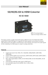
Use the standard HDMI cable and connect the HDMI source to HDMI input port.
Use SDI coaxial cable and connect the SDI output port with the display equipment.
Turn on the power switch.
2.
3.
4.
Notes:
• Each repeater supports transmission distance up to 200m / 600ft with a data rate of
1.5Gbit/s (depending on cable quality).
• Up to 7 repeater units can be connected together; all powered over the coaxial cable by
power injected to the first repeater.
• Longer lengths can be supported with lower speed cameras: for example, 720m /
1200ft for SDI cameras.
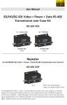
HD-SDI
Repeater
Rx
(Nearest DVR)
HD-SDE-VDR
DVR/NVR side Repeater including Link Power and Control Channel
HD-SDI
Repeater
HD-SDE-VDP
In-line HD-SDI Repeater
HD-SDI
Repeater
Tx
(Camera Side)
HD-SDE-VDR
Camera side HD-SDI Repeater with Control
Camera control signals RS485 and the system power can be injected at the first repeater (nearest
the recorder). Control signals RS485and camera power (if appropriate) can similarly be taken
from the repeater nearest to the camera and feed into the camera itself.
The camera control is via RS-485 and a control signal bandwidth of up to 115KHz is supported.
5