1
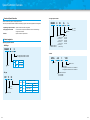
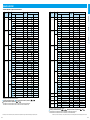
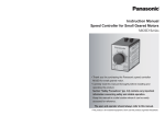
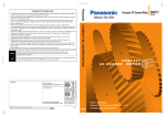
Speed Controller
Contents
• Speed Controller Overview
• Types
• Product infomation for each model
C- 2
C- 4
C- 6
Speed Controller Overview
Overview of Speed Controllers
• Unit type speed controller
• These controllers vary speed of compact geared motors.
• The lineup of the speed controllers is divided into the following 3 types to meet various applications and configuration.
1. Separate type speed controller
2. Unit type speed controller
3. Inverter
MUSN
Speed controller of the basic configuration
A set of a motor and speed controller: Both can be connected through
a single-touch connector.
Speed controller for 3-phase motor
8
Size
• Separate type speed controller
MGSD
B
Output
MUSN : US series
MUXN : UX series
2
Input power
B
Series
100 V
200 V
M1G
3 W to 40 W
Series
60 W to 90 W
6 W to 90 W
Voltage
Code
Code
Speed controller
C-2
6 : 60 mm sq.
(2.36 inch sq.)
7 : 70 mm sq.
(2.76 inch sq.)
8 : 80 mm sq.
(3.15 inch sq.)
9 : 90 mm sq.
(3.54 inch sq.)
L : 100 V
Y : 200 V
6: 6W
15 : 15 W
25 : 25 W
40 : 40 W
60 : 60 W
90 : 90 W
4A
1
Motor output Voltage
V1X
Shape
With control
Compatible motor output
4A : 25 W, 40 W
9A : 60 W, 90 W
31
11 : 100 V
12 : 200 V
Toothed
Output Shape of shaft
Power system
1 : Single phase AC100 V to 110 V 50 Hz/60 Hz
2 : Single phase AC200 V to 230 V 50 Hz/60 Hz
• EX type
DV 11
L
• Inverter
1 : Single phase 100 VAC to 120 VAC
2 : Single phase 200 VAC to 240 VAC
A
G
Toothed
Product designation
• MGSD type
25
Type
31
32
34
EX
Compatible motor output
100 V
200 V
3 W to 10 W
6 W to 20 W
15 W to 40 W
60 W to 90 W
–
25 W to 90 W
C-3
Speed controller
Speed controller
• Possible combination of speed controller and motor
Size
Certified
3
-----
M61X3GV4L
100
MGSDA1
DV1131
6
-----
M61X6GV4L
100
MGSDA1
DV1131
-----
M61X6GV4Y
200
MGSDB2
DV1231
M61X6GV4LG(A)
100
MGSDA1
-----
M61X6GV4DG(A)
110/115
MGSDA1
M61X6GV4YG(A)
200
MGSDB2
M61X6GV4GG(A)
10
90 mm sq.
(3.54 inch sq.)
40
60
90
Output
Motor
Certified
3
-----
6
---------
Speed controller
MGSD type
EX type
M6RX4GV4L
100
MGSDA1
DV1131
M6RX6GV4L
100
MGSDA1
DV1131
M6RX6GV4Y
200
MGSDB2
DV1231
M6RX6GV4LG(A)
100
MGSDA1
-----
-----
M6RX6GV4DG(A)
110/115
MGSDA1
-----
-----
M6RX6GV4YG(A)
200
MGSDB2
-----
M6RX6GV4GG(A)
60 mm sq.
(2.36 inch sq.)
(W)
Voltage
(V)
EX type
Part No.
220/230
MGSDB2
-----
-----
M7RX10GV4L
100
MGSDA1
DV1131
-----
M7RX10GV4Y
200
MGSDB2
DV1231
-----
M7RX15GV4L
100
MGSDA1
DV1132
-----
M7RX15GV4Y
200
MGSDB2
DV1231
M7RX15GV4LG(A)
100
MGSDA1
-----
-----
M7RX15GV4DG(A)
110/115
MGSDA1
-----
-----
M7RX15GV4YG(A)
200
MGSDB2
-----
M7RX15GV4GG(A)
220/230
MGSDB2
-----
-----
M71X10GV4L
100
MGSDA1
DV1131
-----
M71X10GV4Y
200
MGSDB2
DV1231
-----
M71X15GV4L
100
MGSDA1
DV1132
-----
M71X15GV4Y
200
MGSDB2
DV1231
M71X15GV4LG(A)
100
MGSDA1
-----
M71X15GV4DG(A)
110/115
MGSDA1
M71X15GV4YG(A)
200
MGSDB2
M71X15GV4GG(A)
220/230
MGSDB2
-----
-----
M81X15GV4L
100
MGSDA1
DV1132
-----
M81X15GV4Y
200
MGSDB2
DV1231
-----
M81X25GV4L
100
MGSDA1
DV1132
-----
M81X25GV4Y
200
MGSDB2
DV1234
M81X25GV4LG(A)
100
MGSDA1
-----
M81X25GV4DG(A)
110/115
MGSDA1
-----
M81X25GV4YG(A)
200
MGSDB2
-----
M81X25GV4GG(A)
220/230
MGSDB2
-----
-----
M91X40GV4L
100
MGSDA1
DV1132
-----
M91X40GV4Y
200
MGSDB2
DV1234
M91X40GV4LG(A)
100
MGSDA1
-----
M91X40GV4DG(A)
110/115
MGSDA1
-----
M91X40GV4YG(A)
200
MGSDB2
-----
M91X40GV4GG(A)
220/230
MGSDB2
-----
70 mm sq.
(2.76 inch sq.)
10
15
Variable speed reversible motor
Variable speed induction motor
25
MGSD type
Size
80 mm sq.
(3.15 inch sq.)
15
25
90 mm sq.
(3.54 inch sq.)
40
220/230
MGSDB2
-----
-----
M8RX20GV4L
100
MGSDA1
DV1132
-----
M8RX20GV4Y
200
MGSDB2
DV1231
-----
M8RX25GV4L
100
MGSDA1
DV1132
-----
M8RX25GV4Y
200
MGSDB2
DV1234
M8RX25GV4LG(A)
100
MGSDA1
-----
M8RX25GV4DG(A)
110/115
MGSDA1
-----
M8RX25GV4YG(A)
200
MGSDB2
-----
M8RX25GV4GG(A)
220/230
MGSDB2
-----
-----
M9RX40GV4L
100
MGSDA1
DV1132
-----
M9RX40GV4Y
200
MGSDB2
DV1234
M9RX40GV4LG(A)
100
MGSDA1
-----
M9RX40GV4DG(A)
110/115
MGSDA1
-----
M9RX40GV4YG(A)
200
MGSDB2
-----
M9RX40GV4GG(A)
220/230
MGSDB2
-----
-----
M9RZ60GV4L
100
MGSDB1
DV1134
-----
M9RZ60GV4Y
200
MGSDB2
DV1234
M9RZ60GV4LG(A)
100
MGSDB1
-----
M9RZ60GV4DG(A)
110/115
MGSDB1
-----
-----
M9RZ60GV4YG(A)
200
MGSDB2
-----
-----
M9RZ60GV4GG(A)
220/230
MGSDB2
-----
-----
M91Z60GV4L
100
MGSDB1
DV1134
-----
M91Z60GV4Y
200
MGSDB2
DV1234
M91Z60GV4LG(A)
100
MGSDB1
-----
M91Z60GV4DG(A)
110/115
MGSDB1
-----
M91Z60GV4YG(A)
200
MGSDB2
M91Z60GV4GG(A)
220/230
MGSDB2
M91Z60GV4GGC
MGSDB2
-----
M91Z90GV4L
100
MGSDB1
DV1134
-----
M91Z90GV4Y
200
MGSDB2
DV1234
M91Z90GV4LG(A)
100
MGSDB1
-----
M91Z90GV4DG(A)
110/115
MGSDB1
-----
M91Z90GV4YG(A)
200
MGSDB2
-----
M91Z90GV4GG(A)
220/230
MGSDB2
-----
M91Z90GV4GGC
220/230
MGSDB2
-----
* When using a speed controller operative under a wide range of supply voltage (MGSD), the mating motor should be selected
according to the voltage of the power supply to be used.
Motor compliant with China efficiency standards :
Conforming to international standards
MGSD speed controllers are compliant with
and
.
* The models with a motor model number to which “A” is suffixed are not equipped with a capacitor cap.
The models with a motor model number to which “A” is suffixed are not sold or available in Japan.
90
Variable speed motor with
electromagnetic brake
220/230
-----
60
60 mm sq.
(2.36 inch sq.)
6
70 mm sq.
(2.76 inch sq.)
15
80 mm sq.
(3.15 inch sq.)
25
90 mm sq.
(3.54 inch sq.)
40
-----
M9RZ90GV4L
100
MGSDB1
DV1134
-----
M9RZ90GV4Y
200
MGSDB2
DV1234
M9RZ90GV4LG(A)
100
MGSDB1
-----
M9RZ90GV4DG(A)
110/115
MGSDB1
-----
M9RZ90GV4YG(A)
200
MGSDB2
-----
M9RZ90GV4GG(A)
220/230
MGSDB2
---------------------------------
M6RX6GBV4L
M6RX6GBV4Y
M7RX15GBV4L
M7RX15GBV4Y
M8RX25GBV4L
M8RX25GBV4Y
M9RX40GBV4L
M9RX40GBV4Y
100
200
100
200
100
200
100
200
MGSDA1
MGSDB2
MGSDA1
MGSDB2
MGSDA1
MGSDB2
MGSDA1
MGSDB2
-----
DV1131
DV1231
DV1132
DV1231
DV1132
DV1234
DV1132
DV1234
* When using a speed controller operative under a wide range of supply voltage (MGSD), the mating motor should be selected
according to the voltage of the power supply to be used.
Conforming to international standards :
MGSD speed controllers are compliant with
and
* The models with a motor model number to which “A” is suffixed are not equipped with a capacitor cap.
The models with a motor model number to which “A” is suffixed are not sold or available in Japan.
* Please read your User's manual carefully so that you will understand the operation and safety precautions before attempting to operate the system.
C-4
Index
15
Part No.
(V)
Speed controller
(W)
15
80 mm sq.
(3.15 inch sq.)
Voltage
Options
70 mm sq.
(2.76 inch sq.)
Motor
Brake Unit
60 mm sq.
(2.36 inch sq.)
Output
.
* Please read your User's manual carefully so that you will understand the operation and safety precautions before attempting to operate the system.
C-5
• Standard specification (EX type)
• Outline drawing
Power frequency
50 Hz/60 Hz
Rated current
Compatible motor output *1
1A
2.0 A
0.3 A
1A
15 W to 40 W
60 W to 90 W
6 W to 20 W
25 W to 90 W
High-response
High-stability
90 r/min to 1400 r/min / 90 r/min to 1700 r/min
50 r/min to 1400 r/min / 50 r/min to 1700 r/min
5 % or more
3 % or less
Operation change
Speed control range
Speed variation
From external controller, e.g. external speed changer *3
Speed setting
Braking*2
Active while electric braking current is flowing.
5 sec typ.
The braking current will be turned off before the 5-sceond limit as the motor stops.
(Braking current is 2 to 3 times the rated current.)
Electric braking time
Parallel operation
Enabled
Available (typically up to 5 sec (0 to max. speed))
Soft-start/soft-down capability
Operating temperature range
–10 ˚C to 50 ˚C
Storage temperature
–20 ˚C to 60 ˚C
*1 Applicable to Panasonic compact speed variable geared motors. Select motors with applicable output.
*2 Electric braking has no mechanical brake holding mechanism.
To provide brake holding, use our C&B motor or variable speed motor containing electromagnetic brake.
When braking a load having excessively high inertia, durability and life expectancy of motor shaft and gear should be taken into
consideration. Use the motor within the allowable inertia.
*3 EX type is supplied with the external speed changer.
• Outline drawing
93.5(3.68)
Unit: mm (inch)
* Please read your User's manual carefully so that you will understand the operation and safety precautions before attempting to operate the system.
4
3.5
0.7
8.9
ø28.5
3
2
1
38
49
59(2.32)
50(1.97)
(7.5)
Unit: mm (inch)
• Setting of Speed
In the case of the MGSD type, the built-in speed reference is used to set the speed. In the case of the EX type, the
external speed reference is used to set the speed. The figure below shows an example of the relation between the
position of the speed setting knob and the speed of the motor. (Note that there is an approx. 10 % fluctuation due
to variations in the voltage generation of the circuit and tacho-generator.)
Speed (r/min)
Socket is not supplied with the product.
Use octal pin socket (DV0P4560), option,
or Socket (AW68102) recommended by
Panasonic Electric Works Co.,Ltd.
33
36(1.42)
14.2(0.56)
59(2.32)
67.1(2.64)
ø20(ø0.79)
36(1.42)
Socket (accessory)
5
14.2(0.56)
8
EX type
• EX type
60 Hz
50 Hz
1700
1400
1000
500
0
C-6
0.4 A
3 W to 10 W
• MGSD type
50(1.97)
MGSD type
DV1234
Single phase 200 VAC
4
*1 Electric braking has no mechanical holding mechanism.
DV1231
5
Supply voltage
Supply voltage tolerance
Power frequency
Rated input current
Compatible motor output
Speed control range
Speed regulation (against load)
Speed setting
Braking *1
Electric braking time
Parallel operation
Product weight
DV1134
±10 % (at rated voltage)
Operating voltage range
• Standard specification (MGSD type)
MGSDA1
MGSDB1
MGSDB2
Single phase 100 VAC to 120 VAC
Single phase 200 VAC to 240 VAC
±10 % (at rated voltage)
50 Hz/60 Hz
1.0 A
2.0 A
1.0 A
3 W to 40 W
60 W to 90 W
6 W to 90 W
50 Hz : 90 r/min to 1400 r/min 60 Hz : 90 r/min to 1700 r/min
5 % : 1000 r/min, Typical variation at 80 % rated torque
Internal
Activated while electric braking current is flowing.
0.5 sec (typ.): Amount of braking current is 2 times to 3 times the rated current.
Not applicable
80 g
DV1132
Single phase 100 VAC
0
2
4
Position of knob
6
8
Speed (r/min)
EX type
DV1131
Rated voltage
Index
• Soft-start/soft-down
Time can be adjusted up to 5 seconds.
Excellent soft-start/soft-down linearity.
• Selectable response
High-stable and high-response can be selected with the
internal changeover switch to meet the characteristic of the
application.
(Factory setting: high-response)
• Excellent instantaneous stop capability
• Parallel operation
Two or more motors can be controlled from a single
control knob.
• Can link with various control systems
Can control motor(s) in conjunction with different
controlling systems such as PLC (Programmable Logic
Controller). The voltage signal can also be used as control
signal.
Characteristic
Options
<EX type>
EX type
Part No.
Brake Unit
• Internal speed changer
Motor speed can be adjusted from the speed setting knob
on the front panel.
Not necessary to install and connect an external speed
changer to the controller.
• Electric brake enables instantaneous stop.
• Compact 8P plug-in configuration.
• Variable installation options are available.
Terminal blocks, sockets and other various options
(from Panasonic) for panel board can be used.
• Compliant with international standards:
6
<MGSD type>
7
• Features
MGSD type
Speed controller
Speed controller
1800
60 Hz
1500
50 Hz
1000
500
0 1 2 3 4 5 6 7 8 9 10
Position of knob
* Please read your User's manual carefully so that you will understand the operation and safety precautions before attempting to operate the system.
C-7
Wiring diagram (for unidirectional rotation)
Speed controller
Page
MGSD type
C- 9
MGSD type
Speed change only
Unidirectional rotation and electric brake
MGSD type
Normal/reverse rotation and electric brake
Wiring of cooling fan motor (F) or motor with thermal protector (TP)
Wiring to electromagnetic brake (40 W or smaller)
Wiring diagram (for unidirectional rotation)
EX type
C-13
Normal/reverse rotation and electric brake
C-15
EX type
Multispeed setting application
C-16
EX type
Speed change with analog signal
C-17
EX type
C-17
EX type
Parallel operation through external speed changer
C-18
EX type
Parallel operation through analog signal
EX type
Soft-operation
Wiring of cooling fan motor (F) and motor with thermal protector (TP)
Wiring to electromagnetic brake
EX type
C-19
5
C-20
Pin No.
• The motor revolving speed can be set from the speed setting knob on the panel.
• The thick continuous lines represent main circuit. Use conductor of size 0.75 mm2 or larger for the main line.
• The thin continuous lines represent signal circuit. Use conductor of size 0.3 mm2 or larger in the signal circuit.
When the distance from the tachometer generator (TG) is long, use shielded twisted pair cable.
Do not ground the shielding material.
Miniature DIN terminal block
Panasonic AT7803
Speed control knob
This knob adjusts the rotating speed of the motor
from 90 (r/min) to 1400 (r/min) /1700 (r/min) at
50 Hz/60 Hz.
65
Power supply
100 VAC system: Single phase 100 VAC to 120 VAC
200 VAC system: Single phase 200 VAC to 240 VAC
<Precautions>
The input voltage must
be in the range of rated
voltage compatible with
the motor specification.
*Install a noise filter and
surge absorber
to protect against
external noise
and lightning
surge.
43
TG
Gray
Motor
Black
Capacitor
Pink
SW1
Pink
Run
Stop
ON
OFF
TG
7 8 1 2
SW1
Spark killer
R1 C1
7
CW
3
CCW
6
Pin No.
MCCB
SW1
White
Gray
SW2
R1 C1
Spark killer
Rated voltage
input
Black
Motor
SW2
Stop
Run
ON
OFF
ON
CW
*
CCW
SW1 : Power switch
SW2 : Normal/reverse selector switch
Capacitor
Pink
Run
Pink
TG
SW1
100 V supply system
5 A or more at 125 VAC
SW2
200 V supply system
5 A or more at 250 VAC
Spark killer R1+C1
DV0P008A (option)
White
Gray
Black
Capacitor cap
Pink
• National specifications: Option
• Specifications compliant with
overseas standards: Attachment
Motor
Power switch
Ground the return circuit to
the earth terminal.
(100 Ω or less, ø1.6 mm or more).
Tightening torque: 1.0 N·m to 1.5 N·m
* In the case of models with a model
number to which “A” is suffixed, the
capacitor cap is optional.
The models with a model number
to which “A” is suffixed
(not equipped with a capacitor
cap) are not sold or available
in Japan.
Capacitor
(supplied with the motor)
For connection to the capacitor,
see the motor instruction manual.
* Please read your User's manual carefully so that you will understand the operation and safety precautions before attempting to operate the system.
C-8
8
5
Noise filter*
Ground the return circuit to the earth terminal.
(100 Ω or smaller, ø1.6 mm or more).
White
2
1
4
Pink
Surge absorber*
(option)
Clockwise
CCW Counterclockwise
Normal/reverse rotation
1 Wiring diagram (for unidirectional rotation)
Circuit breaker (MCCB)
:5A
<Caution>
Install a ground-fault
circuit interrupter in
the power supply.
6
CW
Rated voltage
input
CW
3
4
C-20
EX type
MCCB
SW1
7
C-18
C-19
EX type
8
Rotating direction viewed
from shaft end
Index
Operation through contactless signal
C-12
C-14
EX type
2
1
C-11
C-12
EX type
Unidirectional rotation and electric brake
C-10
MGSD type
MGSD type
Unidirectional rotation
Options
Speed change only
MGSD type
C- 8
2 Speed change only
Brake Unit
1
2
3
4
5
6
7
8
9
10
11
12
13
14
15
16
17
18
Function
Speed controller
Connection diagram
Speed controller
• Connection diagram list
MGSD type
Speed controller
Speed controller
<Precautions>
1. To change rotating direction of induction motor:
Provide a motor halt period. Switch over SW2 after complete stop of the motor.
2. To change rotating direction of reversible motor:
A motor halt period is not necessary. Switch over SW2 while keeping SW1 turned ON. When configuring
SW2 with relay contacts, use a relay having large gap between contacts (e.g. HL relay from Panasonic) to
prevent malfunction due to short-circuited capacitor.
3. For motors for cooling fan and motors with thermal protector, also refer to page C-12.
4. When using independent relay contacts for SW2 to change over normal/reverse, interlock both contacts
so that they will not close simultaneously.
5. The spark killer consisting of R1 and C1 must be used to protect the relay contacts.
* Please read your User's manual carefully so that you will understand the operation and safety precautions before attempting to operate the system.
C-9
MGSD type
MCCB
SW1
2
1
Rated voltage
input
White
7
Spark killer
C1
3
6
4
External
STOP
SW3 braking
resistor
RUN
SW2
STOP
R1
R2
Black
Motor
Capacitor
Pink
Pink TG
Braking
Run
5
Pin No.
SW1
40 W or larger
SW2
SW3
7
3
6
4
5
Pin No.
RUN
External
braking
resistor
R2
STOP
SW2
STOP
CW
SW3
RUN
Run
ON
RUN
STOP
RUN
Black
Capacitor
Pink
Motor
White
Pink
TG
SW1
100 V supply system
5 A or more at 125 VAC
SW2
200 V supply system
5 A or more at 250 VAC
SW3
Spark killer R1+C1
External braking resistor R2
DC10 V 10 mA
DV0P008A (option)
DV0P003 (option)
<Precautions>
1. When SW2 and SW3 are switched from RUN to STOP, electric braking is applied for approx. 0.5 sec, and
the motor stops instantly.
Difference in switching time between SW2 and SW3 must be 0.1 sec or shorter. If SW2 (SW3) is in RUN
position while SW3 (SW2) is in STOP, abnormal operation occurs (full speed rotation for a short time) and
motor temperature rises excessively.
2. The number of start/stop operations must be 6 times/min or less.
3. For motors for cooling fan and motors with thermal protector, also refer to page C-12.
4. The spark killer consisting of R1 and C1 must be used to protect the relay contacts.
5. R2 limits flow of discharging current upon short-circuiting of the capacitor during braking.
* Please read your User's manual carefully so that you will understand the operation and safety precautions before attempting to operate the system.
C-10
7
8
CW
Spark killer
C1
R1
RUN
SW2
3
6
4
5
STOP
STOP
RUN
SW3
CCW
MCCB
CW
Rated voltage
input
White
SW4
Gray
CW
SW5
CCW
R2
External
braking
resistor
Motor
Black
Capacitor
Braking
Pink
Run
TG
Pink
SW1
RUN
40 W or larger
SW4
SW5
CW
SW1
8
External
braking resistor
R2
RUN STOP
SW2
7
3
6
4
5
Pin No.
C1
CCW
SW4
CW
CCW
SW5
CW
R1
Spark killer
MCCB
Rated voltage
input
Stop Reverse
STOP
RUN
CCW
0.7 sec or longer
SW1 : Power switch
SW2 : RUN/STOP switch
SW3 : Braking start switch
SW4 : Normal/reverse selector switch
Gray
Black
Motor
Capacitor
Braking
ON
SW2
SW3
2
1
Clockwise
CCW Counterclockwise
Pin No.
SW1 : Power switch
SW2 : RUN/STOP switch
SW3 : Brake start switch
Gray
C1
R1
Spark killer
Rated voltage
input
Braking
Speed controller
Speed controller
2
1
8
MCCB
SW1
Stop
SW1
2
1
Rotating direction viewed
from shaft end
Index
8
RUN
Gray
25 W or smaller
Options
Speed controller
CW
• Connection according to this wiring
diagram causes the motor to rotate
clockwise when viewed from the
motor shaft end. To run the motor
counterclockwise, interchange the
connecting point of black and gray
leads.
Brake Unit
25 W or smaller
4 Normal/reverse rotation and electric brake
Speed controller
3 Unidirectional rotation and electric brake
Speed controller
Speed controller
White
STOP
SW3
RUN
Pink
Pink
TG
SW1, SW2 100 V supply system
5 A or more at 125 VAC
SW4, SW5 200 V supply system
5 A or more at 250 VAC
SW3
Spark killer R1+C1
External braking resistor R2
DC10 V 10m A
DV0P008A (option)
DV0P003 (option)
<Precautions>
1. When SW2 and SW3 are switched from RUN to STOP, electric braking is applied for approx. 0.5 sec,
and the motor stops instantly. (Do not operate SW4 and SW5 until the motor stops.)
Difference in switching time between SW2 and SW3 must be 0.1 sec or smaller. If SW2 (SW3) is in RUN
position while SW3 (SW2) is in STOP, abnormal operation occurs (full speed rotation for a short time)
and motor temperature rises excessively.
2. Do not change the motor rotating direction (SW4, SW5) while the motor is running.
3. The number of start/stop operations must be 6 times/min or less.
4. For motors for cooling fan and motors with thermal protector, also refer to page C-12.
5. The spark killer consisting of R1 and C1 must be used to protect the relay contacts.
* Please read your User's manual carefully so that you will understand the operation and safety precautions before attempting to operate the system.
C-11
MGSD type
Ry
1
2
Thermal protector (TP)
Pin No.
F(Black)
F(Black)
SW A
SWA
SWB
TP Blue
Ry
SW B
TP Blue
Closed
ON
Relay
(Ry)
MCCB
ON
Closed
ON
Run
Reset
Rated voltage
input
Ry
Relay
Ry
SW A
Momentary N.O. contact
SW B
Momentary N.C. contact
100 V supply system
125 VAC 5 A or more 3a contact
200 V supply system
250 VAC 5 A or more 3a contact
<Precautions>
1. The thermal protector (TP) is an automatic reset type. To prevent hazards caused by restarting, connect
the TP as shown above. Don’t connect TP directly to the power supply.
2. Once the TP operates, cooling period is required before the operation can restart.
3. Connect the cooling fan motor (F) across pins 1 and 2 on the power terminal.
4. Motor (M) and tachometer generator (TG) should be connected according to corresponding wiring
diagram shown later.
6 Wiring to electromagnetic brake (40 W or smaller)
Speed controller
• Variable speed motor with electromagnetic
brake should be wired as shown below.
SW1
2
1
Pin No.
C1
R1
Spark killer
STOP
MCCB
Rated voltage
input
RUN
SW9
Motor
Yellow
Yellow
Brake
SW1
100 V supply system
5 A or more at 125 VAC
SW9
200 V supply system
5 A or more at 250 VAC
Spark killer R1+C1
Used to set the number
of revolutions.
1/4 W, 20 kΩ, taper B
Closed
DV0P008A (option)
• Soft-start/down control
(supplied with the controller)
Soft-start and soft-down times can
be adjusted by a single setting.
Use this feature to protect the load
from shock caused by sharp speed
change at startup and shutdown of
the motor.
To disable the soft operation, turn
the control fully clockwise.
Power
supply
Circuit breaker (MCCB)
:5A
<Caution>
Install a ground-fault
circuit interrupter in
the power supply.
6
• Maximum speed control
Use this control to adjust the
revolving speed when the external
speed changer is set at the top
speed.
Adjust the speed to 1400 (r/min) or
below at 50 Hz; or 1700 (r/min) or
below at 60 Hz.
4
3
DIN terminal block
AT7803
Panasonic
(extra-cost option)
Power switch
(extra-cost option)
• Operation changeover switch
Select “high-stable” or
“high-response”:
<High-stable>
• Keeps the rotation speed variation TG
low against variation in load.
• Enables a wide range of speed
control.
• Suitable for capability control.
• May fail to maintain constant
rotation speed upon sharp load
change.
<High-response>
• Enables quick response with low
CW
hunting.
• Suitable for positioning
application.
Motor
• May fail to keep rotation speed
variation low against variation in
load.
• Not suitable for controlling wide
range of speed.
5
Index
TG
TG(Pink) Fan motor (F)
Closed
• The thick continuous lines represent main circuit. Use conductor of size 0.75 mm2 or larger for the main line.
• The thin continuous lines represent signal circuit. Use conductor of size 0.3 mm2 or larger in the signal circuit.
When the distance from the tachometer generator (TG) is long, use shielded twisted pair cable.
External speed changer (VR)
Opened
Closed
TP
M
Closed Closed
7 Wiring diagram (for unidirectional rotation)
Options
{
Black
M White
Gray
Ry
EX type
Brake Unit
Speed controller
5 Wiring of cooling fan motor (F) or motor with thermal protector (TP)
Speed controller
Speed controller
Speed controller
7
8 1 2
White
Gray
Pink
Black
Pink
Capacitor
(supplied with motor)
Ground the return circuit to the earth terminal.
(100 Ω or less, ø1.6 mm or more).
Tightening torque: 1.0 N·m to 1.5 N·m
<Precautions>
1. Operate SW9 simultaneously with RUN/STOP switching of other switches, if any.
Placing other switch to RUN position while the brake is active (SW9 at STOP position) causes the motor
to generate heat.
2. For remaining wirings, refer to corresponding wiring diagram.
* Please read your User's manual carefully so that you will understand the operation and safety precautions before attempting to operate the system.
C-12
* Please read your User's manual carefully so that you will understand the operation and safety precautions before attempting to operate the system.
C-13
EX type
8 Speed change only
9 Unidirectional rotation and electric brake
CW
Gray
Black
8
3
6
Motor
Capacitor
2
Pink
Pink
3
6
5
4
TG
R1
C1
CW
R1
Gray
Black
Motor
Capacitor
Pink
Pink TG
Stop
Run
ON
Normal
SW1
SW1 100 V supply system
5 A or more at 125 VAC
SW2 200 V supply system
5 A or more at 250 VAC
R1+C1
DV0P008A (option)
SW2
RUN
Reverse
STOP
CW
Start/stop control with small signal
• With the external speed changer connected,
the motor can be started/stopped with a small
signal through SW6 contact while the power
switch SW1 (see diagram above) is on. The
SW6 provides shorter start-up time than SW1.
3
6
SW6
RUN
5
4
Pin No.
STOP
2
1 VR 3
DC10 V 10 mA
}
External speed changer
(DV0P002)
1/4 W, 20 kΩ, taper B
To TG
<Precautions>
1. Power (SW1) should be turned on at least 0.5
sec before turning on of the start signal (SW6).
2. When the motor is not operated for a
prolonged time, turn off power switch (SW1).
Operation from maximum speed control
• When no external speed changer is required,
the speed can be adjusted from the
maximum speed control.
3
6
5
4
R3 20 kΩ 1/4 W
To TG
Pin No.
<Precautions>
1. Connect a fixed resistor (R3) in place of
external speed changer (VR).
* Please read your User's manual carefully so that you will understand the operation and safety precautions before attempting to operate the system.
C-14
CW
R1
Motor
Capacitor
SW2
R2
3
SW1 100 V supply system
5 A or more at 125 VAC
SW2 200 V supply system
5 A or more at 250 VAC
SW3
STOP
SW3
RUN
2
1 VR 3
Pink
Pink
TG
DC10 V 10 mA
R1+C1
DV0P008A (option)
R2
DV0P003 (option)
Pin No.
40 W or larger
2
1
CCW
<Precautions>
1. To change rotating direction of induction motor:
Provide a motor halt period. Switch over SW2 after complete stop of the motor.
2. To change rotating direction of reversible motor:
A motor halt period is not necessary. Switch over SW2 while keeping SW1 turned ON. When configuring
SW2 with relay contacts, use a relay having large gap between contacts (e.g. HL relay from Panasonic) to
prevent malfunction due to short-circuited capacitor.
3. For motors for cooling fan and motors with thermal protector, also refer to page C-20.
4. When using independent relay contacts for SW2 to change over normal/reverse, interlock both contacts
so that they will not close simultaneously.
5. The spark killer consisting of R1 and C1 must be used to protect the relay contacts.
STOP
RUN
8
RUN
SW1 : Power switch
SW2 : Normal/reverse selector switch
Rated voltage
input
Black
C1
5
4
SW1 MCCB
Gray
Speed controller
This wiring diagram causes the motor to rotate clockwise
when viewed from the motor shaft end.
To run the motor counterclockwise, interchange the
connecting point of black and gray leads.
• Connection according to this wiring
diagram causes the motor to rotate
clockwise when viewed from the
motor shaft end. To run the motor
counterclockwise, interchange the
connecting point of black and gray
leads.
Gray
7
6
Pin No.
Pin No.
SW1
White
2
1 VR 3
2
1
Rated voltage
input
White
SW2
CCW
C1
MCCB
SW1 MCCB
Index
1 VR 3
5
4
7
8
SW1
25 W or smaller
Options
Speed controller
White
7
2
1
Rated voltage
input
Speed controller
MCCB
Speed controller
SW1
2
1
Normal/reverse rotation
Brake Unit
Unidirectional rotation
Speed controller
Speed controller
CW
Black
8
RUN
7
3
6
5
4
STOP
SW2
R1
C1
STOP
SW3
RUN
Run
SW1
R2
Capacitor
Braking
Rated voltage
input
Motor
2
1 VR 3
Pink
Pink
Pin No.
<Precautions>
1. When SW2 and SW3 are switched from RUN to
STOP, electric braking is applied for approx. 5
sec, or until the motor stops.
SW2 and SW3 must be operated
simultaneously. Otherwise, abnormal operation
occurs (full speed rotation for a short time),
causing the motor temperature rises
excessively.
2. The number of start/stop cycles must be 6
times/min or less.
3. When using cooling fan motor or motor with
thermal protector, also see page C-20.
4. Insert R1 and C1 to protect relay contact.
5. R2 restricts discharge current in case of
capacitor short circuit during braking.
Run
ON
SW2
SW3
White
Stop
Braking
RUN
STOP
RUN
SW1 : Power switch
SW2 : RUN/STOP switch
SW3 : Brake start switch
TG
Operation from maximum speed control
• When no external speed changer is required,
the speed can be adjusted from the maximum
speed control.
3
6
5
4
SW3 STOP
RUN
R3 20 kΩ 1/4 W
}
To TG
Pin No.
<Precautions>
1. Connect a fixed resistor (R3) in place of
external speed changer (VR).
* Please read your User's manual carefully so that you will understand the operation and safety precautions before attempting to operate the system.
C-15
EX type
10 Normal/reverse rotation and electric brake
SW2
RUN
C1
CW
SW5
CCW
2
1 VR 3
5
4
Motor
Black
SW1, SW2 100 V supply system 5 A or more at 125 VAC
SW4, SW5 200 V supply system 5 A or more at 250 VAC
Capacitor
Pink
SW3
TG
Pink
DC10 V 10 mA
R1+C1
DV0P008A (option)
R2
DV0P003 (option)
7
3
6
5
4
STOP
R1
C1
STOP
SW3
RUN
Braking
SW1 MCCB
CW
SW4
CCW
CW
SW5
CCW
Rated voltage
input
Gray
Black
Capacitor
Motor
Normal
3 1
VR2
5
4
3 1
VR3
}
To TG
Pin No.
3
2
1
VR1
2
3 1
VR2
5
4
SW3, SW8
2
3 1
VR3
VR1
3
DC10 V 10 mA
DV0P002
VR2
(option)
VR3
}
To TG
Pin No.
ON
SW2
SW3
RUN
STOP
SW4
SW5
CW
2
1 VR 3
Pink
Pink
TG
<Precautions>
1. When SW2 and SW3 are switched from RUN to
STOP, electric braking is applied for approx. 5
sec, or until the motor stops. (Do not operate
SW4 and SW5 until the motor stops completely.)
SW2 and SW3 must be operated simultaneously.
Otherwise, abnormal operation occurs (full speed
rotation for a short time), causing the motor
temperature rises excessively.
2. Do not change the rotating direction (SW4, SW5)
while the motor is running.
3. The number of start/stop cycles must be 6
times/min or less.
4. When using cooling fan motor or motor with
thermal protector, also see page C-20.
5. Insert R1 and C1 to protect relay contact.
6. R2 restricts discharge current in case of
capacitor short circuit during braking.
RUN
CCW
SW1 : Power switch
SW2 : RUN/STOP switch
SW3 : Braking start switch
SW4,SW5 : Normal/reverse selector switch
Operation from maximum speed control
• When no external speed changer is required,
the speed can be adjusted from the maximum
speed control.
3
6
5
4
SW3
No braking applied
Braking
Stop Reverse
SW1
White
Pin No.
RUN
R3 20 kΩ 1/4 W
}
To TG
Pin No.
<Precautions>
1. Connect a fixed resistor (R3) in place of
external speed changer (VR).
SW1
2
1
3
MCCB
Rated voltage
input
MAX
DC5 V
6
GND
}
5
4
To TG
Pin No.
Braking applied
2
1
3
6
5
4
SW1
SW7
MCCB
Rated voltage
input
MAX
DC5 V
STOP
GND
RUN
}
To TG
<Precautions>
1. Turn on power switch SW1 approx. 0.5 sec earlier than the
analog start signal.
2. For repetitive run/stop operations, use the analog signal while
keeping SW1 ON.
3. Soft-operation can be adjusted from the soft-start and
soft-down controls or by using analog signal.
4. On the maximum speed control, set the maximum motor
revolving speed that may be achieved at the maximum analog
signal value (e.g. 3 VDC).
5. The absolute maximum rating of analog signal is 5 VDC.
The system should be designed to use standard 3 VDC analog
signal. If the signal voltage exceeds 3 VDC, the circuit diagram
shown below should be used for wiring.
SW1
6
5
4
GND
5 A or more at 125 VAC
200 V supply system
5 A or more at 250 VAC
R1
1 kΩ
emax
(r/min)
1700
1400
R2
1000
To TG
0
emax
3
– 1 kΩ
emax : Analog signal max. voltage
500
Pin No.
100 V supply system
SW7DC10 V 10 mA
R2
3
Pin No.
STOP
* Please read your User's manual carefully so that you will understand the operation and safety precautions before attempting to operate the system.
C-16
VR1
2
Speed controller
R2
SW2
RUN
1
2
SW8
<Precautions>
1. Set external speed changers VR1, VR2 and VR3 to 3 different speeds and select the desired speed from
SW8.
2. When activating the brake, simultaneously switch over SW3 and RUN-STOP of other switches.
3. For remaining wirings, refer to the corresponding wiring diagrams.
Speed controller
40 W or larger
Speed controller
Speed controller
8
2
RUN
6
12 Speed change with analog signal
Pin No.
2
1
SW8
6
STOP
Index
6
Clockwise
CCW Counterclockwise
Gray
R1
R2
STOP
SW3
RUN
3
CW
White
Speed controller
8
STOP
Rotating direction viewed
from shaft end
SW3
3
Speed controller
7
3
Speed controller
CW
SW4
CCW
Rated voltage
input
Braking applied
Options
Speed controller
2
1
No braking applied
SW1 MCCB
Brake Unit
25 W or smaller
11 Multispeed setting application
Speed controller
Speed controller
1
2
3 (V)
Analog signal (DC)
R1 : External resistor: 1 kΩ
R2 : External resistor
6. Revolution speed “0” signal should not exceed 0.1 VDC.
7. The input speed pattern (curve) may not be exactly
reflected on the motor speed, due to inertial effect of the
load, especially during stop sequence.
8. The percentage ripple of analog voltage signal should be
2 % or less.
9. For other wirings, refer to the corresponding circuit/wiring
diagrams.
10. When using the braking feature, motor wiring (pins 1, 7
and 8) should be in accordance with pages C-15 and C-16.
To activate braking, switch SW2 and SW7 at the same
time.
If SW2 is in RUN position while SW7 is in STOP,
abnormal operation occurs (full speed rotation for a short
time); or if SW7 is in RUN position while SW2 is in
STOP, motor temperature rises excessively.
* Please read your User's manual carefully so that you will understand the operation and safety precautions before attempting to operate the system.
C-17
EX type
15 Parallel operation through analog signal
Pin No.
}
To TG
5
4
2
Tr
STOP
1 VR 3
RUN
}
To TG
Pin No.
Internal equivalent circuit
MAX
DC5 V
3
6
Tr
STOP
}
5
4
1 kΩ
6.2 V
1 μF
RUN
22 kΩ
GND
To TG
1 μF
1 kΩ
Pin No.
6
Speed controller
Speed controller
5
4
Pin No.
3
6
5
4
Pin No.
To TG
5
4
Pin No.
To TG
To TG
<Precautions>
1. Power switch SW1 should be turned on approx. 0.5
sec before the operation start signal from SW6.
2. When repeating run/stop cycles, turn on/off only SW6
while keeping SW1 turned ON. In this way, the motor
can be controlled by using a small signal. To stop
operation for a long time, also turn off SW1.
3. Soft-start/soft-down period is the time required for the
equipment to start up from stop state to full speed
when the external speed changer is set at maximum
value.
4. Soft-start/soft-down control, when at the full
clockwise position, disables the soft-down function.
As the stop signal is input, power supply to the motor
is turned off immediately. However, the revolving
speed gradually decreases in proportion to the inertia
of the load and motor starts free-running stop
sequence.
5. Soft-start/soft-down control can set maximum time
length of approx. 5 seconds (Typ. at FCCW). The
setting may be exceeded if the inertia of the load is
too large.
6. For other electrical connections, refer to
corresponding circuit/wiring diagrams.
• Soft-start and electric brake
Electrical wirings are the same as for “Unidirectional
rotation and electric brake” and “Normal/reverse
rotation and electric brake”.
Adjust the soft-start time from the soft-start/down
control.
Motor will stop quickly by electric brake despite the
volume settings of soft-down operation.
* Please read your User's manual carefully so that you will understand the operation and safety precautions before attempting to operate the system.
C-18
3
6
To TG
16 Soft-operation
2
3
6
5
4
Pin No.
5
• Soft-start, soft-down
3 VR 1
3
6
SW1
2
1
MCCB
Index
14 Parallel operation through external speed changer
<Precautions>
1. The resistance Rs of the external speed changer
VR should be as follows:
Rs = 20/N (kΩ)
where, N is the number of motors.
2. For synchronous operation or ratio operation,
desired revolving speeds must be set from the
maximum speed control.
Soft-start and soft-down controls and operation
changeover switch must be set to the same
position.
3. Wirings from the external speed changer VR should
be connected to the same pins (No.5 and 6) on the
controller.
4. Malfunction may occur as the number of devices
operated in parallel increases.
To secure correct operation, connect a noise filter
to each unit.
5. For other electrical connections, refer to
corresponding circuit/wiring diagrams.
3
Speed controller
5
4
1 VR 3
3
6
Speed controller
RUN
2
Speed controller
Tr STOP
Analog signal and brake
Options
Speed controller
3
6
Braking applied
DC
0 V to +3 V
GND
Brake Unit
No braking applied
<Precautions>
The input impedance of the controller is approx. 100 kΩ.
The output impedance of the analog signal source
should be determined based on the total input
impedance of the speed controllers.
Speed controller
• Small signal relays SW3, SW6 and SW7 can be replaced with transistor.
Speed controller
13 Operation through contactless signal
Speed controller
Speed controller
Rated voltage
input
To motor
3
6
RUN
SW6
2
DOWN
1 VR 3
}
5
4
To TG
Pin No.
SW1
100 V supply system
5 A or more at 125 VAC
200 V supply system
5 A or more at 250 VAC
SW6
DC10 V 10 mA
Soft-start
Soft-down
Speed
SW1
SW6
ON
RUN
0.5 sec or more
* Please read your User's manual carefully so that you will understand the operation and safety precautions before attempting to operate the system.
C-19
EX type
Speed controller
Unit type
• Features
Ry
2
SW A
Thermal protector (TP)
Pin No.
SW B
Ry
SW B
Relay
(Ry)
ON
TP
TP Blue
M
Opened
Closed
MCCB
Closed
Closed
ON
Closed
Run
ON
Reset
Rated voltage
input
<US series>
TG
Fan motor (F)
Ry
SW A
Momentary N.O. contact
SW B
Momentary N.C. contact
100 V supply system
125 VAC 5 A or more 3a contact
200 V supply system
250 VAC 5 A or more 3a contact
<Precautions>
1. The thermal protector (TP) is an automatic reset type. To prevent hazards caused by restarting, connect the
TP as shown above. Don't connect TP directly to the power supply.
2. Once the TP operates, cooling period is required before the operation can restart.
3. Connect the cooling fan motor (F) across pins 1 and 2 on the power terminal.
4. Motor (M) and tachometer generator (TG) should be connected according to corresponding wiring diagram
shown later.
18 Wiring to electromagnetic brake
Speed controller
SW1
2
1
Pin No.
R1
MCCB
• UX series
• Please refer to pages B-324 to B-340 to check the specification and combination of motor and speed controller.
• When ordering the motor and speed controller as a set, place an order using the unit model number.
• Part No.
Capacity
Voltage
100 V
6W
200 V
100 V
15 W
200 V
100 V
200 V
100 V
200 V
100 V
60 W
200 V
100 V
90 W
STOP RUN
SW9
Motor
Yellow
Yellow
Brake
SW1
100 V supply system
5 A or more at 125 VAC
SW9
200 V supply system
5 A or more at 250 VAC
R1+C1
DV0P008A (option)
<Precautions>
1. SW9 should be switched to RUN or STOP at the same time as the other switches are switched to RUN or
STOP.
If the other switches are set to RUN while the brake is energized (SW9 in STOP position), the motor will
generate heat.
2. For other wirings, refer to the corresponding circuit/wiring diagrams.
If the application is speed change without using electric braking (page C-14), perform wiring according to
“Start/stop control with small signal”.
Output
Rated voltage
Power frequency
Speed control range
Speed variation
Speed setting
Operating temperature
Storage temperature
Soft-start/soft-down time
UX series
6 W : 15 W : 25 W : 40 W : 60 W : 90 W
single-phase 100 VAC / single-phase 200 VAC
50 Hz / 60 Hz
90 r/min to 1400 r/min / 90 r/min to 1700 r/min
5 % (standard value)
Digital
0 ˚C to 40 ˚C
–10 ˚C to 60 ˚C
0.1 sec to 30 sec
• The 90 W models contain a thermal protector to prevent burnout for motor.
• Please refer to pages B-324 to B-340 to check the specification and combination of motor and speed controller.
• When ordering the motor and speed controller as a set, place an order using the unit model number.
• Part No.
Capacity
6W
15 W
25 W
40 W
90 W
* Please read your User's manual carefully so that you will understand the operation and safety precautions before attempting to operate the system.
200 V
UX series
DVUX606L
DVUX606Y
DVUX715L
DVUX715Y
DVUX825L
DVUX825Y
DVUX940L
DVUX940Y
DVUX960L
DVUX960Y
DVUX990L
DVUX990Y
• US series
60 W
C-20
• Specification
40 W
Rated voltage
input
US series
* When connected (B-323 page) unit motor.
25 W
• Variable speed motor with electromagnetic brake should be wired as shown below.
• Provided with quick-connect* socket
• Can be extended up to 5 m through extension cable
(option)
Index
UX series
Ry
C1
• Provided with quick-connect* socket
• Can be extended up to 5 m through extension cable
(option)
• The CPU enables the following various functions:
1. Digital setting of revolving speeds
2. Instantaneous conversion of gear head speed and
conveyor speed
3. Digital display of actual speed
4. Soft-start, soft-down
5. Backup of setting conditions
6. Set locking
Options
TG(Pink)
SW A
TP Blue
Black
M White
Gray
F(Black)
F(Black)
Ry
Closed Closed
Closed
<UX series>
Brake Unit
Speed controller
17 Wiring of cooling fan motor and motor with thermal protector
1
Speed controller
Speed controller
• Specification
Voltage
100 V
200 V
100 V
200 V
100 V
200 V
100 V
200 V
100 V
200 V
100 V
200 V
US series
DVUS606L
DVUS606Y
DVUS715L
DVUS715Y
DVUS825L
DVUS825Y
DVUS940L
DVUS940Y
DVUS960L
DVUS960Y
DVUS990L
DVUS990Y
Output
US series
6 W : 15 W : 25 W : 40 W : 60 W : 90 W
Rated voltage
single-phase 100 VAC / single-phase 200 VAC
Speed control range
90 r/min to 1400 r/min / 90 r/min to 1700 r/min
Power frequency
Speed variation
Speed setting
Operating temperature
Storage temperature
Soft-start/soft-down time
50 Hz / 60 Hz
5 % (standard value)
Analog
–10 ˚C to 40 ˚C
–20 ˚C to 60 ˚C
• The 90 W models contain a thermal protector to prevent burnout for motor.
* Please read your User's manual carefully so that you will understand the operation and safety precautions before attempting to operate the system.
C-21
Unit type UX series
• Operating method and preparation (UX series)
YES
Wiring
diagram
CCW
Motor connector
10(0.39)
2 m(78.74)
Operating
switch
80(3.15)
52.5(2.07)
RUN
STOP
MODE
2.5(0.098)
MAX140(5.51)
60(2.36)
White, Black: Power cable
Green: Frame ground
Trimmer
potentiometer
Unit: mm (inch)
• Indicates that the soft-start time is being set or
Factory
soft-start process is activated.(To enter SS mode, setting
press and hold MODE key for at least 1 second.) 0 sec
• Indicates that the soft-down time is being set or
soft-down process is activated.
(Press the MODE key while in SS mode.)
• Set the indication magnification Factory
setting
(Select from MODE key)
1.000
• Display the rotation speed
(Select from MODE key)
• Settings/revolving speed
• Power-on state setting
(In the SET mode, set the revolving speed to the
max. and then press and hold
key for 5 seconds
or more. “YES” or “NO” is displayed.)
RUN STOP SS
SD SET.L
RATIO
SET
REAL
MOTOR SPEED
r/min
• RUN/STOP key
• MODE key
•
SIG.
OUT
MODE
• Unit of revolving speed
(Displayed when RATIO is set to 1 or more.)
key Increases the set value.
• Indicates that the reading is motor revolving speed.
(Active only when RATIO is set to 1 or more.)
• ADJ control
Use this trimmer potentiometer if discrepancy
is found between the preset and the actual
rotation speeds.
•
key Decreases the set value.
• Motor connector
• Power-on state changeover switch
• Normal/reverse switch
Factory
setting
NO
Factory
setting
CW
• Capacitor for motor
White, Black: Power cable
Green: Frame ground
<CAUTION>
1. When using a gear head,
check the direction of rotation
of its output shaft. The direction
is not common to all models.
2. The fan of a fan-cooled motor
starts to run as the controller is
turned on.
Wiring diagram
Capacitor cap
Power supply
Circuit breaker (MCCB)
: 5A
<Caution>
Install a ground-fault
circuit interrupter in
the power supply.
RUN STOP SS
SD SET.L
RATIO
SET
REAL
Power
switch
SIG.
OUT
Extension cord
MOTOR SPEED
r/min
MODE
* In the case of models with a
model number to which “A” is
suffixed, the capacitor cap is
optional.
The models with a model
number to which “A” is suffixed
(not equipped with a capacitor
cap) are not sold or available in
Japan.
Capacitor
<Recommended circuit breakers>
Sensata Technologies, Inc.
Controller
Motor
Type single-phase: IELH-1-11-63-5A-M
Rated current 5 A, current breaking characteristic
Ground the return circuit to
DELAY63
Ground the return circuit to
the earth terminal.
Recommended current breaking characteristic:
(100 Ω or smaller, ø1.6 mm or more). the earth terminal.
DELAY61 to 63
• Contact to 03-6895-1005
Factory
setting
0 sec
• Set lock indication
(To enter the set lock mode, simultaneously
press MODE ,
and
keys.)
• Set the revolution speed Factory
(Select from MODE key) setting
90
(100 Ω or less, ø1.6 mm or more).
Tightening torque: 1.0 N·m to 1.5 N·m
(Supplied with the speed controller)
In case products of 40 W or less,
a capacitor is built in to the speed
controller body.
In case products of 60 W or
more,a capacitor is external
connection.
Do not remove the line of
capacitor, please use it as such.
* Please read your User's manual carefully so that you will understand the operation and safety precautions before attempting to operate the system.
C-22
Power-on state setting
(1) “YES”
Upon power-on, the unit reproduces the state as it
was turned off.
Previous state
“STOP”
“RUN”
Upon power-on
→
Startup (after approx. 2 sec)
→
(2) “NO”
Upon power-on, the unit is in stop mode regardless of
the state at the previous power off.
To restart, operate RUN-STOP key.
Previous state
“STOP”
“RUN”
→
→
Upon power-on
Stop
Stop
Index
Exampie: 200 V
• Stop
Select from RUN/STOP
• Run
Select from RUN/STOP
•Turn on power.
•Setting of display magnification(RATIO mode), rotation speed (SET
mode), soft start/down (SS/SD mode).
•Press the RUN key, motor will rotating.
The state of the unit upon power-up can be preset from the power-on state setting switch.
• Names and functions
UX series
•Check the Power-on state setting.
•Setting the Normal/reverse switch.
(Switch on the back of the controller.)
•Connect the “motor connector”.
Options
Power cable:
80.5(3.17)
NO
Power-on state
changeover switch
LCD
Brake Unit
Exampie: 200 V
Normal/reverse
switch
CW
90(3.54)
UX series
5(0.20)
100(3.94)
• Outline drawing
Speed controller
Speed controller
• Modes of operation (UX series)
RATIO mode
By setting the speed in unit of motor revolving speed
multiplied by the factor or by displaying the actual speed,
gear head output shaft speed or belt conveyor travel
speed can be converted. The RATIO mode is used to set
the factor.
Selection of indication magnification can be made from
and keys.
Reduction gear ratio setting value (to display the
settings in terms of gear head output shaft speed)
<“SET” or “REAL” reading = motor revolving speed
divided by gear reduction settings>
The reduction ratios of Panasonic gear head are stored in
the unit, choose the suitable one by using
and keys:
1.000→3→... 100 ...→202 ...→1000 ...→2020
Multiple number setting value (to display the settings in
terms of the speed of belt conveyor)
<“SET” or “REAL” reading = motor revolving speed
multiplied by multiplication factor>
Multiplication can be set by the factor of 0.005 to 0.995:
select the desired one from
and keys.
1.000→0.995→...→0.015→0.010→0.005
(in unit of 0.005)
SET mode
In this mode, the revolving speed can be set to a value
within the range shown below, by using
and keys.
[With reading magnification 1.000]
Value can be set in unit of 10 r/min.
<Example>
• Power frequency 50 Hz :
90→100→110 ...→1400 r/min
• Power frequency 60Hz :
90→100→110 ...→1400 ...1700 r/min
[With reading magnification other than 1.000]
Readings are based on the reading magnification setting
in RATIO mode and gear reduction ratio setting. Desired
value can be selected among the values shown below, by
using
and keys.
<Example> Reduction gear ratio = 3
Selection unit is 10/3 r/min. The reading rounds off fraction.
• Power frequency 50 Hz: 29.9→33.3→36.6 ...→466.6 r/min
• Power frequency 60 Hz: 29.9→33.3→36.6 ...→466.6 ...
→566.6 r/min
<Example> Magnification = 0.500
Selection unit is 10 x 0.500. The reading rounds off fraction.
• Power frequency 50 Hz: 45.0→50.0→55.0 ...→700.0
• Power frequency 60 Hz: 45.0→50.0→55.0 ...→700.0 ...
850.0
[Note] Exception: reading magnification 1.000
“MOTOR SPEED r/min” is displayed.
Only “r/min” is displayed when the value exceeds
1.000. Otherwise, nothing is displayed.
REAL mode
In the REAL mode, motor's real revolutions multiplied by
the reading magnification is displayed.
[Reading magnification 1.000]
The speed is displayed in unit of 5 r/min.
<Example>
0→5 ...→90→100→110 ...→1400 ...→1700 r/min
[With reading magnification other than 1.000]
Readings are based on the reading magnification setting
in RATIO mode and gear reduction ratio setting.
<Example> Reduction gear ratio = 3
Selection unit is 5/3 r/min. The reading rounds off fraction.
0→1.6 ...→29.9→33.3→36.6 ...→466.6 ...→566.6 r/min
<Example> Magnification = 0.500
Selection unit is 10 x 0.500. The reading rounds off fraction.
0→2.5 ...→45.0→50.0→55.0 ...→700.0 ...→850.0
[Note] Exception: reading magnification 1.000
“MOTOR SPEED r/min” is displayed.
Only “r/min” is displayed when the value exceeds 1.000.
Otherwise, nothing is displayed.
* Please read your User's manual carefully so that you will understand the operation and safety precautions before attempting to operate the system.
C-23
Unit type UX
Unit
series
type
Soft start (SS) / Soft down (SD) setting mode
To enter SS mode, press and hold MODE key for at least 1 second. To enter SD mode, press the MODE key while in SS mode.
Note 1) Soft start (SS) · Soft down (SD)
r/min
1500
750
5S
SS
Note 2)
In the practical application, speed change time will be longer than
the Soft start · Soft down time if the load inertia is large.
SD
Unit type US series
• Outline drawing
52.5(2.07)
Speed change knob
(13(0.51))
80.5(3.17)
Low
3.5(0.14)
Power cable: 2m(78.74)
White, Black: Power cable
Green: Frame ground
Speed change knob
(13(0.51))
ø22
(ø0.87)
80.5(3.17)
Power indicator LED
(110(4.33))
89(3.5)
52.5(2.07)
Capacitor leadwires (350±30 mm)
Unit: mm (inch)
Motor connector
Wiring
diagram
Low
High
STOP
Capacitor
(40 W or smaller versions
contain this capacitor in
the controller box.)
Operation switch
Unit: mm (inch)
ø4(ø0.16)
(61(2.40))
W3
M0PC20M20
100 V
MUSN960GL
M0PC5M40
200 V
MUSN960GY
M0PC25M20
100 V
MUSN990GL
M0PC6.2M38
200 V
MUSN990GY
L
50.2
(1.98)
50
(1.97)
50.2
(1.98)
50
(1.97)
W
26.7
(1.05)
30.5
(1.20)
31
(1.22)
30.5
(1.20)
D
37
(1.46)
41
(1.61)
41
(1.61)
41
(1.61)
H
36
(1.42)
41.5
(1.63)
42
(1.65)
41.5
(1.65)
T
4
(0.16)
4
(0.16)
4
(0.16)
4
(0.16)
12(0.47)
(W4)
Unit: mm (inch)
Voltage Designation
Capacitor cap
part No.
M0PC5026
M0PC5032
M0PC5032
M0PC5032
(W2)
Unit: upper (mm)
lower (inch)
W1
W1
50
(1.97)
50
(1.97)
50
(1.97)
50
(1.97)
W2
48
(1.89)
48
(1.89)
48
(1.89)
48
(1.89)
W3
26
(1.02)
32.5
(1.28)
32.5
(1.28)
32.5
(1.28)
* Please read your User's manual carefully so that you will understand the operation and safety precautions before attempting to operate the system.
C-24
RUN
• Front panel
(removable)
Wiring diagram
Capacitor cap
Power supply
Extension cord
Circuit breaker (MCCB)
: 5A
<Caution>
Install a ground-fault
circuit interrupter in
the power supply.
Power
switch
* In the case of models with a
model number to which “A” is
suffixed, the capacitor cap is
optional.
The models with a model
number to which “A” is suffixed
(not equipped with a capacitor
cap) are not sold or available in
Japan.
Capacitor
(Supplied with the speed controller)
In case products of 40 W or less,
a capacitor is built in to the speed
controller body.
In case products of 60 W or
more,a capacitor is external
connection.
Do not remove the line of
(100 Ω or less, ø1.6 mm or more).
capacitor, please use it as such.
Tightening torque: 1.0 N·m to 1.5 N·m
<Recommended circuit breakers>
Sensata Technologies, Inc.
Controller
Motor
Type single-phase: IELH-1-11-63-5A-M
Rated current 5 A, current breaking characteristic
Ground the return circuit to
DELAY63
Ground the return circuit to
the earth terminal.
Recommended current breaking characteristic:
(100 Ω or smaller, ø1.6 mm or more). the earth terminal.
DELAY61 to 63
1. Connect the “motor connector”.
2. Make sure that the RUN/STOP switch is in “STOP” position. Connect the power cable to the AC source.
3. Turn on power. “Power” indicator will light.
4. Place the RUN/STOP switch in “RUN” position, and the motor starts.
CAUTION: Do not place the switch lever in between RUN and STOP.
5. To stop the motor, move the lever to “STOP” position.
Note that the RUN/STOP switch does not turn on/off power supply: when not using the motor for a long period, turn off
the main power switch.
6. The electric fan, if used with the motor, rotates as the power to the speed controller is turned on and stops as the
controller power source is turned off.
• Unidirectional rotatio
Direction when viewed from motor output shaft end
Clockwise
Counterclockwise
Connect COM to CW
Connect COM to CCW
• Normal/reverse rotation
H
10(0.39)
max
Unit: mm (inch)
17(0.67)
10(0.39)
Capacitor
part No.
High
Terminal “CW” or “CCW” on the controller rear panel should be left open.
Capacitor cap
Quick connect tab,
Faston 187 (t0.5 mm, t0.02 inch)
Label
60(2.36)
Power cable: 2 m(78.74)
White, Black: Power cable
Green: Frame ground
T
ø4.3
(ø0.17)
hole
1.5(6.06)
W
D
2–ø2.5(ø0.098)hole
L
6.2
(0.244)
Capacitor
Terminal block
(w/ cover)
3.5(0.14)
Low
STOP
• Changing direction of rotation (US series)
Nameplate
Front panel
76(2.99)
RUN
• Speed setting knob
• ADJ
With the speed setting knob turned fully clockwise, adjust
the trimpot (normally covered with the front panel) for the
revolutions shown below: 50 Hz: 1400 r/min
60 Hz: 1700 r/min
• Operating method (US series)
Operation
switch
60(2.36)
• RUN/STOP switch
• Contact to 03-6895-1005
90(3.54)
10(0.39)
76(2.99)
• 60 W or larger
RUN
Nameplate
Terminal block
(w/ cover)
Exampie: 200 V
High
STOP
100(3.94)
Exampie: 200 V
Power indicator LED
(110(4.33))
89(3.5)
ø22
(ø0.87)
• 40 W or smaller
(w/ internal capacitor)
Motor
connector
90(3.54)
100(3.94)
US series
• Power indicator
Index
Speed controller
US series
Options
0
• Names and functions
Brake Unit
The Soft start · Soft down time is defined as the time required to
change revolving speed between 0 r/min and 1500 r/min.
<Example>
When the soft-start time is set to 10 seconds and “SET” revolving
speed is 750 r/min, then,
750 r/min
10 ×
=5
1500 r/min
This means that 5 seconds are required to change from 0 r/min to
750 r/min. The same applies to “SD”.
The Soft start · Soft down time in each mode to be
set individually, and you can select a value by
and key. In unit of 0.1 sec, up to 30 sec.
Unit type US series
Speed controller
Speed controller
W4
22
(0.87)
29.5
(1.16)
29.5
(1.16)
29.5
(1.16)
When it is necessary to select the rotating
direction, connect the switch as shown in
the figure.
[Note]
Do not operate this switch while the motor
is running.
Switch specification
• Single-pole double-throw: ON-OFF-ON
• 100 V power: 5 A at 200 VAC or more
• 200 V power: 3 A at 400 VAC or more
[Note]
When a gear head is connected, the direction of its output shaft may
or may not be the same as that of motor shaft depending on the
reduction ratio.
40 W or smaller
(Built-in capacitor)
Remove
the jumper
lead.
COM
CW
CCW
AC
AC
FG
60 W or larger
Remove
the jumper
lead.
Switch
COM
CW
CCW
AC
AC
FG
Switch
Capacitor
Please do not remove
the connection of
the capacitor.
* Please read your User's manual carefully so that you will understand the operation and safety precautions before attempting to operate the system.
C-25
Unit type
Speed controller
inverter
• Features
• Mounting method (UX series, US series)
UX series, US series
Unit: mm (inch)
Object
2- M4 screw
Options
)
0
81+10 (3.19 +0.039
90 ±0.2 (3.54 ±0.008)
2- M4 or 2- ø4.5(ø0.18)
Brake Unit
• Extremely compact and low noise (compared with
preceding models).
• Can control 3-phase 200 V motor by using single-phase
100 V power (use of voltage doubler).
Single-phase 200 V version is available.
• Easy to operate control knob.
• External normal/reverse switches.
• Applicable to only 3-phase motors.
<Mounting through square holes>
Speed controller
Speed controller
Controller
53 +10
(2.09 +0.039
)
0
Index
Mounting procedure
1. Drill 2 square holes in the object.
2. Secure the controller and front panel with 2 M4 screws.
<Mounting without using square hole>
• Standard specification
ø7(ø0.28)
ø23(ø0.91)
ø17(ø0.67)
Front panel
4 – ø3.5(ø0.14)
(Cross section A)
2.0 mm max.
90˚
ø3.5
(ø0.14)
Controller
Caution
Wall thickness of the equipment where the controller is to be mounted should be 2 mm or less.
Mounting procedure
1. Drill 2 square holes in the wall of the object.
2. Remove the front panel from the controller.
3. Secure the controller body with M3 flat-head screws and nuts.
4. Place the front panel on the wall and secure the panel with M4 screws and nuts.
<To install controller and motor separately>
When installing the speed controller at a distance more than 1 m from the motor, use optional
“extension cord” that is supplied as standard accessory (allowable distance 5 m).
Refer to page D-4 (Option).
* Please read your User's manual carefully so that you will understand the operation and safety precautions before attempting to operate the system.
Applicable motor (W)
Output volt-ampere (kVA)
*1
*2
Rated output current (A)
*3
*4
Regenerative braking torque
*5
External signal
Protective function
Electronic-thermal
Ambient temperature
Ambient humidity
0.11/0.16
0.19/0.27
0.11/0.16
0.20/0.28
25/40
60/90
25/40
0.49/0.7
0.28/0.4
60/90
0.49/0.7
3-phase 200 VAC to 230 VAC
Single-phase 200 VAC to 230 VAC
50 Hz/60 Hz ±5 %
Acceleration/deceleration time setting
Operation switch, normal/reverse switch
M1G9A2V1X
±10 %
Frequency
Frequency setting
M1G4A2V1X
Single-phase 100 VAC to 110 VAC
Permissible voltage variation
Overload current rating
M1G9A1V1X
3-phase 200 VAC to 220 VAC
Voltage
Controlling system
M1G4A1V1X
0.28/0.4
Rated output voltage
Output frequency range
Control method
(Cross section A)
ø6.5
(ø0.26)
26 ±0.2(1.02 ±0.008)
12 ±0.2(0.47 ±0.008)
2- M4 screw
Nut
Power
source
90 ±0.2(3.54 ±0.008)
Body mounting screw (M3 flat-head)
13.2 ±0.2
(0.52 ±0.008) 2 – ø7.5(ø0.30)
50 ±0.2
(1.97 ±0.008)
C-26
Part number
Unit: mm (inch)
Output rating
15 ±0.2(0.59 ±0.008)
US series only
Low noise sine-wave PWM
1.0 Hz to 120 Hz (factory setting: 60 Hz)
0 sec to 30 sec
150 % 1 min.
Short time average deceleration torque 100 %
Panel control
Panel switch
(input): operation instruction, normal/reverse instruction, free-run stop;
(output): abnormal signal
Undervoltage, overcurrent, overvoltage, instantaneous power
interruption, stall, overload shutdown, self-diagnosis trip
25 W/40 W
60 W/90 W
25 W/40 W
60 W/90 W
–10 °C to +40 °C (no freezing)
90 % RH (no dewing)
Atmosphere
Indoor (free from foreign objects such as corrosive gas and dust)
Protective construction
Closed type (IP20)
Altitude
Up to 1000 m
*1.Panasonic 3-phase compact geared motors MoM series 4 models.
*2.Measured at rated output voltage at 220 V (M1GoA1V1X), 230 V (M1GoA2V1X).
*3.When using a gear head, keep the output frequency 60 Hz, or below.
*4.When set to “0”, actual time is 0.05 sec.
*5.Regenerative braking torque refers to a short-time averaged deceleration and not a continuous torque.
Deceleration at a frequency higher than the fundamental frequency provides lower torque. No internal braking resistor is provided.
*6.Electromagnetic brake power supply voltage of the motor with an electromagnetic brake please use the AC230 V from AC200 V.
Please do not use the output of the inverter for the power supply of the electromagnetic brake.
There is when the brake can not be released.
* Before using the product, carefully read through “Instruction manual” to understand the safety precautions and operation of it.
* Please read your User's manual carefully so that you will understand the operation and safety precautions before attempting to operate the system.
C-27
inverter
• Layout drawing
• Option
3.0(0.12)
W U
3-phase
Motor
• Power supply cord (DV0P137)
40(1.57)
I1
I2
I3
O1
COM
3000(118.11)
Terminal M3P0.5
Black
Bk : Power supply
W : Power supply
Gn : GND
White
90(3.54)
Terminal M4P0.7
• Noise filter (DV0P140)
24(0.94)
40(1.57)
30(1.18)
6-ø3.5(ø0.14)
Prepare optional parts before connecting the unit to motor
external terminal.
IN
• Outline drawing
60(2.36)
4-M3P0.5
63(2.48)
72(2.83)
81(3.19)
Unit: mm (inch)
(13(0.51))
Green
0.75 mm2(0.03 inch2)
3-core ø7(ø0.28)
Terminal M4P0.7
Abnormal signal output terminal
Vce Max = 24 VDC
Ic max = 50 mA
(COM common open collector)
131(5.16)
40(1.57)
Index
RUN/STOP switch
Normal/reverse switch
Free run to stop switch
External control
extension cord
(option)
Motor extension cord
(optin)
E
16(0.63)
ø5.1(ø0.2) hole
Options
V
51.5(2.03)
S/L2
17.5(0.69)MAX
34
(1.34)
R/L1
ø25.5(ø1.00)
Rated
supply
voltage
Power supply cord
(option)
Unit: mm (inch)
Brake Unit
MCCB
6.5(0.26)
• Data line filter (DV0P031)
Speed controller
Speed controller
13.5(0.53)
15(0.59)
33(1.30)
13.5(0.53)
Low
High
STOP
RUN
Label
105.5(4.15)
CCW
100(3.94)
90(3.54)
• Motor extension cord
POWER SUPPLY
R
L1
S
L2
V E
WU
I1
I2
I3
O1
COM
Front panel removed
Option part No. L : m (inch)
DV0P13802
2(78.74)
DV0P13803
3(118.11)
DV0P13805
5(196.85)
• External control extension cord
L
30(1.18)
Connector : IL-5S-S3L-(N)
Pin : IL-C2-10000
(Japan Aviation Electronics Industry)
1
MOTOR
80.5(3.17)
Gn : GND
R :U
W :V
Bk : W
0.75 mm2(0.03 inch2) 4-core 10(ø0.39) black
2 – ø 4.5(ø 0.18)
52.5(2.07)
DIP switch
1. Double speed
selector
(x1/x2)
2. Max. frequency
selector
(60 Hz/50 Hz)
3. Electronic
thermal selector
L
CW
4.5(0.18)
Connector : 5557-06R-210
Pin : 5556TL
(Molex)
5
5-core shielded cable, gray
90(3.54)
Terminal M4P0.7
Option part No. L : m (inch)
DV0P13902
2(78.74)
DV0P13903
3(118.11)
DV0P13905
5(196.85)
Connector
Pin No.
5
4
3
2
1
Conductor
color
W
R
Bk
Y
Gn
Terminal
symbol
I1
I2
I3
O1
COM
(for acceleration/deceleration setting)
* Please read your User's manual carefully so that you will understand the operation and safety precautions before attempting to operate the system.
C-28
* Please read your User's manual carefully so that you will understand the operation and safety precautions before attempting to operate the system.
C-29