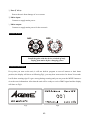
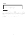
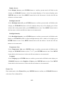
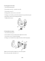
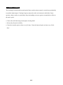
1
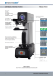
LED‐MS700PE User Guide
Professional LED Moving Head
CONTENTS
1. Safety Instruction .............................................................................................. 2
2. Installations ....................................................................................................... 3
3. Technical Specifications.................................................................................... 4
4. How To Set The Unit......................................................................................... 5
4.1 Control Panel............................................................................................... 5
4.2 Gobo Wheel................................................................................................. 6
4.3 Power On Display ....................................................................................... 6
4.4 Main Function ............................................................................................. 7
4.5 Home Position Adjustment........................................................................ 16
5. Control By Universal DMX Controller........................................................... 18
5.1 DMX 512 Connection ............................................................................... 18
5.2 DMX Address Setting ............................................................................... 19
5.3 DMX512 Configuration ............................................................................ 20
6. Troubleshooting............................................................................................... 22
7. Fixture Cleaning .............................................................................................. 24
1C
1. Safety Instruction
WARNING
Please read carefully the instruction, which includes important information
about the installation, usage and maintenance.
Please keep this User Guide for future consultation. If you sell the unit to another user, be sure that
they also receive this instruction manual.
Important:
Damages caused by the disregard of this user manual are not subject to warranty. The dealer will not
accept liability for any resulting defects or problems.
y
Unpack and check carefully that there is no transportation damage before using the unit.
y
The unit is for indoor use only. Use only in a dry location.
y
DO install and operate by qualified operator.
y
DO NOT allow children to operate the fixture.
y
Use safety chain when fixing the unit. Handle the unit by carrying its base instead of head only.
y
The unit must be installed in a location with adequate ventilation, at least 50cm from adjacent
surfaces.
y
Be sure that no ventilation slots are blocked, otherwise the unit will be overheated.
y
Before operating, ensure that the voltage and frequency of power supply match the power
requirements of the unit.
y
It’s important to ground the yellow/green conductor to earth in order to avoid electric shock.
y
Maximum ambient temperature Ta: 40℃. DO NOT operate it when the temperature is higher.
y
DO NOT connect the device to any dimmer pack.
y
During initial start-up some smoke or smell may arise. This is a normal process and does not
necessarily mean that the device is defective, and it will decrease gradually within 15 minutes.
y
Make sure there are no flammable materials close to the unit while operating to avoid fire
hazard.
y
Examine the power wires carefully, replace them immediately if there is any damage.
y
Unit’s surface temperature may reach up to 85℃. DO NOT touch the housing bare-handed
during its operation, and allow about 15 minutes for cooling the unit down before replacing
bulb or maintenance as it could be very hot.
y
Avoid any inflammable liquids, water or metal objects entering the unit. Once it happens, cut
off the mains power immediately.
y
DO NOT operate in dirty or dusty environment, do clean fixtures regularly.
y
DO NOT touch any wire during operation as there might be a hazard of electric shock.
2C
y
Avoid power wires together twist other cables.
y
Disconnect mains power before fuse/lamp replacement or servicing.
y
Replace fuse/lamp only with the same type.
y
In the event of serious operating problem, stop using the unit immediately.
y
Never turn on and off the unit time after time.
y
The housing, the lenses, or the ultraviolet filter must be replaced if they are visibly damaged.
y
DO NOT open the unit as there are no user serviceable parts inside.
y
Never try to repair the unit by yourself. Repairs carried out by unskilled people can lead to
damage or malfunction. Please contact the nearest authorized technical assistance center if
needed.
y
Disconnect the mains power if the fixture is has not been used for a long time.
y
DO use the original packing materials before transporting it again.
Caution:
y
To prevent or reduce the risk of electrical shock or fire, do not expose the unit to rain or
moisture.
y
Hot lamp explosion hazard. Do not open the unit within 15 minutes after switching off.
y
DO replace the bulb once it is damaged, deformed or life-expired.
y
DO NOT look directly at the light while the bulb is on.
y
Never touch bulb with bare fingers, as it is very hot after using.
y
DO NOT start on the unit without bulb enclosure or when housing is damaged.
Product Items:
y
User manual
y
2 x Omega clamps
2. Installations
Unpacking the fixture (for flight case pack only)
1. Stop the flight case via the brake sheet above the wheels.
2. Unlock the lock module and open the cover board.
3. Prop the cover board with lid bracket.
3C
4. Take out the fixture.
5. Unlock the lock module take out omega clamps.
Installations:
1.
Bolt each clamp (1) to the Omega holder with screw and lock nut through the hole in the
holder.
2.
Fasten the omega holders (2) on the bottom of the base by inserting quick-lock fasteners (3)
into the holes of the base and tighten fully clockwise.
3.
Hang the fixture to the support (4) through clamp and fasten the screws (5). Fasten the safety
cable (6) through the bottom of the base and over the support.
Fig.1
Fig.2
Attention:
y
Always ensure that the structure to which you are attaching the unit is secure and is able to
support a weight of 10 times of the unit’s weight without any harming deformation.
y
Make absolute sure that the unit is firmly fixed in way that no vibrating or slipping would
occur during operation.
y
The equipment must be installed beyond the areas where persons may walk by or be seated.
y
The rigging has to be operated by or under the guide of the skilled person.
3. Technical Specifications
y
Very long 30,000 hour life span
y
DMX Control: 16/17 channels
y
Motorized focus through DMX control
y
Operation Modes: DMX, Master/Slave, Sound Active
y
Built-in programs under Master/Slave triggered by music
y
Smooth 0-100% dimming and variable strobe speeds
y
One rotating gobo wheel with seven gobos and white
y
One fixed gobo wheel with eight gobos and white
4C
y
Color wheel with seven colors plus white
y
Prism, rotating prism and iris included
y
Automatic pan/tilt position correction
y
No mercury, No IR or UV light radiation
y
y
y
y
y
y
y
Voltage:
Power consumption:
Light Source:
Beam Angle:
Fuse:
Dimension:
Weight:
AC 100-240V~50/60Hz
330W
1 x180W LED
13°
6.3A
436 x 344 x 588mm
17.5Kgs
4. How To Set The Unit
4.1 Control Panel
Front view
Rear view
① Display:
Show the various menus and the selected functions
② LED:
DMX
MASTER
SLAVE
SOUND
On
On
On
Flashing
DMX input present
Master Mode
Slave Mode
Sound activation
③ Button:
MENU
DOWN
UP
ENTER
To select the programming functions
To go backward in the selected functions
To go forward in the selected functions
To confirm the selected functions
④ DMX input/output:
For DMX512 link, use 3/5-pin XLR plug cable to link the unit together.
5C
⑤ Fuse (T 6.3A):
Protect the unit from damage of over current.
⑥ Mains input:
Connect to supply mains power.
⑦ Mains output:
Connect to supply mains power for the next unit.
4.2 Gobo Wheel
DANGER!
Install the gobos with the device switched off only.
Unplug from mains before changing gobos!
4.3 Power On Display
Every time you turn on the unit, it will run built-in program to reset all motors to their home
position, the display will show as following Fig1, you may hear some noises for about 20 seconds.
It will show warning sign if it goes wrong during resetting and you can press the MENU button to
view the error information. After that the unit will be ready to receive DMX signal and the display
will show as Fig2:
Fig1.
Fig2.
6C
Explanation:
001
17 Channel
Show start address
Show channel mode is 17channels mode
Base 30°C
Show temperature of base is 30°C
Lamp 29°C
Show temperature of lamp is 29°C
4.4 Main Function
To select any of the given functions, press the MENU button up to when the required one is
showing on the display. Select the function by ENTER button and the display will blink. Use
DOWN and UP button to change the mode. Once the required mode has been selected, Press
ENTER button to store. Back to the main functions without any change press the MENU button or
wait for 8 seconds.
Hold MENU button to quit menu mode, the unit will run the built-in program you selected.
The main functions are shown below:
7C
8C
DMX Functions
Enter menu mode, select DMX Functions, press ENTER button to confirm, use UP/DOWN button
to select DMX Address, Mode or View DMX Value.
DMX Address—DMX512 address setting
Select DMX Address, press ENTER button to confirm, the present address will blink on the
display, use UP/DOWN button to adjust the address from 0 to 512, press ENTER button to
store. Press MENU button back to the last menu or let the unit idle one minute to exit menu
mode.
Mode—Mode setting
Select Mode, press ENTER button to confirm, the present channel mode will blink on the
display, use UP/DOWN button to choose the channel mode(16 channel mode or 17 channel
mode), press ENTER button to store. Press MENU button back to the last menu or let the unit
idle one minute to exit menu mode.
View DMX Value
Select View DMX Value, press ENTER button to confirm. Channel function and its value
will show on the display, use UP/DOWN button to view other DMX value. Press MENU
button back to the last menu or let the unit idle one minute to exit menu mode.
9C
Show Settings
Enter menu mode, select Show Settings, press ENTER button to confirm, use UP/DOWN button
to select Offline Mode, Show Mode, Slave Mode, Focus 1, Focus 2, Sound Trigger or Sound
Sensitivity.
Offline Mode
Select Offline Mode, press ENTER button to confirm, present mode will blink on the display,
use UP/DOWN button to select M/S (Master/ Slave Show), Hold or Blackout, once selected,
press ENTER button to store. Press MENU button back to the last menu or let the unit idle
one minute to exit menu mode.
Show Mode
Select Show Mode, press ENTER button to confirm, present mode will blink on the display,
use UP/DOWN button to select Show 1, Show 2, Show 3 or Show4, press ENTER button to
store. Press MENU button back to the last menu or let the unit idle one minute to exit menu
mode.
Slave Mode
Select Slave Mode, press ENTER button to confirm, present mode will blink on the display,
press UP/DOWN button to select Slave 1 or Slave 2, press ENTER button to store. Press
MENU button back to the last menu or let the unit idle one minute to exit menu mode.
Focus 1
Select Focus 1, press ENTER button to confirm, present mode will blink on the display, use
UP/DOWN button to adjust the value from 0 to 255, press ENTER button to store. Press
MENU button back to the last menu or let the unit idle one minute to exit menu mode.
Focus 2
Select Focus 2, press ENTER button to confirm, present mode will blink on the display, use
UP/DOWN button to adjust the value from 0 to 255, press ENTER button to store. Press
MENU button back to the last menu or let the unit idle one minute to exit menu mode.
10C
Sound Trigger—Sound Mode
Select Sound Trigger, press ENTER button to confirm, present mode will blink on the display,
use UP/DOWN button to select Off (Sound Mode off) or On (Sound Mode On), press
ENTER button to store. Press MENU button back to the last menu or let the unit idle one
minute to exit menu mode.
Sound Sensitivity
Select Sound Sensitivity, press ENTER button to confirm, present mode will blink on the
display, use UP/DOWN button to adjust the sound sensitivity from 0 to 100 , press ENTER
button to store. Press MENU button back to the last menu or let the unit idle one minute to exit
menu mode.
Fixture Settings
Enter menu mode, select Fixture Settings, press ENTER button to confirm, use UP/DOWN
button to select Pan Inverse, Tilt Inverse, P/T Feedback, Iris Inverse, BL.O. P/T Moving, BL.O.
Color Change, BL.O. Gobo Change.
Pan Inverse
Select Pan Inverse, press ENTER button to confirm, present mode will blink on the display,
use UP/DOWN button to select No (normal) or Yes (pan inverse), press ENTER button to
store. Press MENU button back to the last menu or let the unit idle one minute to exit menu
mode.
Tilt Inverse
Select Tilt Inverse, press ENTER button to confirm, present mode will blink on the display,
use UP/DOWN button to select No (normal) or Yes (tilt inverse), press ENTER button to
store. Press MENU button back to the last menu or let the unit idle one minute to exit menu
mode.
P/T Feedback — pan/tilt Feedback
Select P/T Feedback, press ENTER button to confirm, present mode will blink on the display,
press UP/DOWN button to select No (Pan or tilt’s position will not feedback while out of step.)
11C
or Yes (Feedback while pan/tilt out of step. ), press ENTER button to store. Press MENU
button back to the last menu or let the unit idle one minute to exit menu mode.
Iris Inverse
Select Iris Inverse, press ENTER button to confirm, present mode will blink on the display,
use UP/DOWN button to select No (normal) or Yes (iris inverse), press ENTER button to
store. Press MENU button back to the last menu or let the unit idle one minute to exit menu
mode.
BL.O. P/T Moving—Blackout while pan/tilt moving
Select BL.O. P/T Moving, press ENTER button to confirm, present mode will blink on the
display, use UP/DOWN button to select No (normal while pan/tilt moving) or Yes (blackout
while pan/tilt moving), press ENTER button to store. Press MENU button back to the last
menu or let the unit idle one minute to exit menu mode.
BL.O. Color Change—Blackout while change color
Select BL.O. Color Change, press ENTER button to confirm, present mode will blink on the
display, use UP/DOWN button to select No (normal while changing color) or Yes (blackout
while changing color), press ENTER button to store. Press MENU button back to the last
menu or let the unit idle one minute to exit menu mode.
BL.O. Gobo Change—Blackout while change gobo
Select BL.O. Gobo Change, press ENTER button to confirm, present mode will blink on the
display, use UP/DOWN button to select No (normal while changing gobo) or Yes (blackout
while changing gobo), press ENTER button to store. Press MENU button back to the last
menu or let the unit idle one minute to exit menu mode.
Display Settings
Enter menu mode, select Display Settings, press ENTER button to confirm, use UP/DOWN
button to select Display Inverse, Backlight Auto Off, Backlight Intensity or Temperature unit
and Language.
12C
Display Inverse
Select Display Inverse, press ENTER button to confirm, present mode will blink on the
display, use UP/DOWN button to select No (normal display) or Yes (inverse display), press
ENTER button to store. Press MENU button back to the last menu or let the unit idle one
minute to exit menu mode.
Backlight Auto Off
Select Backlight Auto Off, press ENTER button to confirm, present mode will blink on the
display, use UP/DOWN button to select No (display always on) or Yes (display goes off one
minute after exiting menu mode), press ENTER button to store. Press MENU button back to
the last menu or let the unit idle one minute to exit menu mode.
Backlight Intensity
Select Backlight Intensity, press ENTER button to confirm, present mode will blink on the
display, use UP/DOWN button to adjust backlight intensity from 1 (dark) to 10 (bright), press
ENTER button to store. Press MENU button back to the last menu or let the unit idle one
minute to exit menu mode.
Temperature Unit
Select Temperature Unit, press ENTER button to confirm, present mode will blink on the
display, use UP/DOWN button to select ℃ or ℉, press ENTER button to store. Press MENU
button back to the last menu or let the unit idle one minute to exit menu mode.
Language
Select Language press ENTER button to confirm, present mode will blink on the display, use
UP/DOWN button to select English or Chinese, press ENTER button to store. Press MENU
button back to the last menu or let the unit idle one minute to exit menu mode.
Fixture Test
Enter menu mode, select Fixture Test, press ENTER button to confirm, use UP/DOWN button to
select Auto Test or Manual Test
13C
Auto Test
Select Auto Test, press ENTER button to confirm, the unit will run built-in programs to
automatically test pan, tilt, color, gobo, gobo rotation, prism, prism rotation, frost. Press
MENU button back to the last menu or exit menu mode after auto test.
Manual Test
Select Manual Test, press ENTER button to confirm, the present channel will show on the
display, use UP/DOWN button to select channel, press ENTER button to confirm, then use
UP/DOWN button to adjust the value, press ENTER button to store, the fixture will run as the
channel value indicates. Press MENU button back to the last menu or exit menu mode let the
unit idle one minute.
Fixture Information
Enter menu mode, select Fixture Information, press ENTER button to confirm, use UP/DOWN
button to select Fixture use time, LED use time or Firmware Version.
Fixture use time
Select Fixture use time, press ENTER button to confirm, fixture use time will show on the
display, press MENU button to exit.
LED use time
Select LED use time, press ENTER button to confirm, lamp on time will show on the display,
press ENTER button to confirm, use UP/DOWN button to select Exit or Reset Time, press
ENTER button to confirm. Press MENU button back to the last menu or exit menu mode let
the unit idle one minute.
Firmware Version
Select Firmware Version, press ENTER button to confirm, firmware version will show on
the display, press MENU button back to exit.
Reset Functions
Enter menu mode, select Reset Functions, press ENTER button to confirm, use UP/DOWN
button to select Pan/Tilt, Color, Gobo, Prism, Iris, Focus or All.
14C
Pan/Tilt—Reset Pan/Tilt
Select Pan/Tilt, Press ENTER button to confirm, use UP/DOWN button to select Yes (the
unit will run built-in program to reset pan and tilt to their home positions) or No, press
ENTER button to store. Press MENU button back to the last menu or let the unit idle one
minute to exit menu mode.
Color—Reset Color
Select Color, Press ENTER button to confirm, use UP/DOWN button to select Yes (the unit
will run built-in program to reset color wheel to their home positions) or No, press ENTER
button to store. Press MENU button to exit.
Gobo—Reset Gobo
Select Gobo, Press ENTER button to confirm, use UP/DOWN button to select Yes (the unit
will run built-in program to reset gobo wheel) or No, then press ENTER button to store. Press
MENU button back to the last menu or let the unit idle one minute to exit menu mode.
Prism—Reset Prism
Select Prism, press ENTER button to confirm, use UP/DOWN button to select Yes (the unit
will run built-in program to reset prism) or No, press ENTER button to store. Press MENU
button to exit.
Iris—Reset Iris
Select Iris, press ENTER button to confirm, use UP/DOWN button to select Yes (the unit will
run built-in program to reset iris to its home positions) or No, press ENTER button to store.
Press MENU button back to the last menu or let the unit idle one minute to exit menu mode.
Focus—Reset Focus
Select Focus, press ENTER button to confirm, use UP/DOWN button to select Yes (the unit
will run built-in program to reset focus to its home positions) or No, press ENTER button to
store. Press MENU button to exit.
All—Reset All
Select All, press ENTER button to confirm, use UP/DOWN button to select Yes (the unit will
15C
run built-in program to reset all motors to their home positions) or No, press ENTER button to
store. Press MENU button to exit.
Special Functions
Enter menu mode, select Special Functions, press ENTER button to confirm, the Factory Setting
will show on the display, press ENTER button to confirm, then use UP/DOWN button to select
Yes (the unit will run build-in program to reset to factory settings) or No. Press MENU button to
exit.
4.5 Home Position Adjustment
Press MENU button into menu mode, then press the ENTER button for about 3 seconds into offset
mode to adjust the home position. Select the function by ENTER button. Use UP and DOWN
button to choose the submenu, press the ENTER button to store and automatically return to the last
menu. Press MENU button to exit.
Pan—pan home position adjust
Enter offset mode, Select Pan, press ENTER button to confirm, the present position will blink
on the display, use UP/DOWN button to offset the value from -128 to 127, press ENTER button to
store. Press MENU button to exit.
16C
Tilt—Tilt home position adjust
Enter offset mode, Select Tilt, press ENTER button to confirm, the present position will blink
on the display, use UP/DOWN button to offset the value from -128 to 127, press ENTER button to
store. Press MENU button to exit.
Color1—Color1 home position adjust
Enter offset mode, Select Color1, press ENTER button to confirm, the present position will
blink on the display, use UP/DOWN button to offset the value from -128 to 127, press ENTER
button to store. Press MENU button to exit。
Color2—Color2 home position adjust
Enter offset mode, Select Color2, press ENTER button to confirm, the present position will
blink on the display, use UP/DOWN button to offset the value from -128 to 127, press ENTER
button to store. Press MENU button to exit。
Gobo1—Gobo1 home position adjust
Enter offset mode, Select Gobo1, press ENTER button to confirm, the present position will
blink on the display, use UP/DOWN button to offset the value from -128 to 127, press ENTER
button to store. Press MENU button to exit.
RGobo1—Gobo1 rotation home position adjust
Enter offset mode, Select RGobo1, press ENTER button to confirm, the present position will
blink on the display, use UP/DOWN button to offset the value from -128 to 127, press ENTER
button to store. Press MENU button to exit.
Gobo2—Gobo2 home position adjust
Enter offset mode, Select Gobo 2, press ENTER button to confirm, the present position will
blink on the display, use UP/DOWN button to offset the value from -128 to 127, press ENTER
button to store. Press MENU button to exit.
Iris—Iris home position adjust
Enter offset mode, Select Iris, press ENTER button to confirm, the present position will blink
on the display, use UP/DOWN button to offset the value from 0 to 255, press ENTER button to
store. Press MENU button to exit.
17C
Prism—Prism home position adjust
Enter offset mode, Select Prism, press ENTER button to confirm, the present position will
blink on the display, use UP/DOWN button to offset the value from 0 to 255, press ENTER button
to store. Press MENU button to exit.
R Prism—Prism rotation home position adjust
Enter offset mode, Select R Prism, press ENTER button to confirm, the present position will
blink on the display, use UP/DOWN button to offset the value from -128 to 127, press ENTER
button to store. Press MENU button to exit.
Focus—Focus home position adjust
Enter offset mode, Select Focus, press ENTER button to confirm, the present position will
blink on the display, use UP/DOWN button to offset the value from 0 to 255, press ENTER button
to store. Press MENU button to exit.
5. Control By Universal DMX Controller
5.1 DMX 512 Connection
1. At last unit, the DMX cable has to be terminated with a terminator. Solder a 120 ohm 1/4W
resistor between pin 2(DMX-) and pin 3(DMX+) into a 3-pin XLR-plug and plug it in the
DMX-output of the last unit.
2. Connect the unit together in a `daisy chain` by XLR plug from the output of the unit to the
18C
input of the next unit. The cable can not branched or split to a `Y` cable. DMX 512 is a very
high-speed signal. Inadequate or damaged cables, soldered joints or corroded connectors can
easily distort the signal and shut down the system.
3. The DMX output and input connectors are pass-through to maintain the DMX circuit, when
power is disconnected to the unit.
4. Each lighting unit needs to have an address set to receive the data sent by the controller. The
address number is between 0-511 (usually 0 & 1 are equal to 1).
5. The end of the DMX 512 system should be terminated to reduce signal errors.
6. 3 pin XLR connectors are more popular than 5 pin XLR.
3 pin XLR: Pin 1: GND, Pin 2: Negative signal (-), Pin 3: Positive signal (+)
5 pin XLR: Pin 1: GND, Pin 2: Negative signal (-), Pin 3: Positive signal (+)
Pin 4/5: Not used.
5.2 DMX Address Setting
If you use a universal DMX controller to control the units, you have to set DMX address from 1 to
512 so that the units can receive DMX signal.
Press MENU button to enter menu mode, select DMX Functions, press ENTER button to confirm,
use UP and DOWN button to select DMX Address, press ENTER button to confirm, the present
address will blink on the display, use UP and DOWN button to adjust the address from 0 to 512,
press ENTER button to store. Press MENU button back to the last menu or let the unit idle one
minute to exit menu mode.
Please refer to the following diagram to address your DMX512 channel for the first 4 units:
Channel Mode
Unit 1
Unit 2
Unit 3
Unit 4
16 channels
1
17
33
49
17 channels
1
18
35
52
19C
5.3 DMX512 Configuration
16 Channels Mode:
20C
17 Channels Mode:
21C
6. Troubleshooting
Following are a few common problems that may occur during operation. Here are some
suggestions for easy troubleshooting:
A. The unit does not work, no light and the fan does not work
1. Check the connect power and main fuse.
2. Measure the mains voltage on the main connector.
3. Check the power on LED to see if it can be light up or not.
B. Not responding to DMX controller
1. DMX LED should be on. If not, check DMX connectors, cables to see if they are linked
properly.
2. If the DMX LED is on and no response to the channel, check the address settings and DMX
polarity.
3. If you have intermittent DMX signal problems, check the pins on connectors or on PCB of the
unit or the previous one.
4. Try to use another DMX controller.
5. Check to see if the DMX cables run near or run alongside to high voltage cables that may cause
damage or interference to DMX interface circuit.
C. One of the channels is not working well
1. The stepper motor might be damaged or the cable connected to the PCB is broken.
2. The motor’s drive IC on the PCB might be out of condition.
D. The lamp is cutting out intermittently
1. The lamp is not working well. Check the mains voltage either too high or too low.
2. Internal temperature may be too high. Check if replacement of fan is needed on the head.
22C
E. If the pan belt is broken
1. Turn off the mains power.
2. Loosen the screws (A),open the cover (B).
3. Loosen the screws (C).
4. Unplug all the connect wires over the belt.
5. Change a new belt (D), put the belt around the axis gear and motor gear.
6. Plug all the connect wires back upon the belt.
7. Tighten all the screws.
F. If the tilt belt is broken
1. Turn off the mains power.
2. Loosen all the screws (A) and open the right arm cover (B).
3. Loosen the screws (C) that fix the bridge.
4. Change a new belt (D). Please adjust the tension of the belt properly.
Note: do not fix the belt too tight as it is can easily rupture.
Reverse the procedures from step 3 to 2.
23C
7. Fixture Cleaning
The cleaning of internal and external optical lenses and/or mirrors must be carried out periodically
to optimize light output. Cleaning frequency depends on the environment in which the fixture
operates: damp, smoky or particularly dirty surrounding can cause greater accumulation of dirt on
the unit’s optics.
y Clean with soft cloth using normal glass cleaning fluid.
y Always dry the parts carefully.
y Clean the external optics at least every 20 days. Clean the internal optics at least every 30/60
days.
24C
Declaration of Conformity
We declare that our products (lighting equipments) comply with the following
specification and bears CE mark in accordance with the provision of the
Electromagnetic Compatibility (EMC) Directive 89/336/EEC.
EN55103-1: 2009 ; EN55103-2: 2009; EN62471: 2008;
EN61000-3-2: 2006 + A1:2009 + A2:2009; EN61000-3-3: 2008.
&
Harmonized Standard
EN 60598-1:2008 + All:2009; EN 60598-2-17:1989 + A2:1991; EN 62471:2008;
EN 62493: 2010
Safety of household and similar electrical appliances
Part 1: General requirements
Innovation, Quality, Performance