1
lIlllllllllllllllllllllllllllllllllllllllllllllllllllllllllllllllllllllllll
USO05469275A
United States Patent [19]
[11]
Patent Number:
Edgar
[45]
Date of Patent:
[54] METHOD AND APPARATUS FOR
GRAYSCALE ADJUSTMENT
WO9l/l6785
10/1991
5,469,275
Nov. 21, 1995
WIPO .
OTHER PUBLICATIONS
[75] Inventor: Albert D. Edgar, Austin, Tex.
Aldus Photostyler Version 1.1, “User Manual”, Second
Edition, Jun. 1992, Aldus Corporation, pp. ii-402.
Aldus Photostyler Version 1.1, “Getting Started”, Second
Edition, Jun. 1992, Aldus Corporation, pp. ii—76.
[73] Assignee: International Business Machines
Corporation, Annonk, N .Y.
Picture Publisher for Windows 3.0, “Reference Guide”,
[21] Appl. No.: 925,710
[22] Flled:
[51]
[52]
[58]
1992, Micrografx Corp., pp. iii-index D—9.
Picture Publisher for Windows 3.0, “Learning Guide”, 1992,
Micrografx Corp., pp. iii-index B—3.
Aug' 4’ 1992
Int. Cl.6
.......................... .. H04N 1/40
US. Cl. .......... ..
358/458; 358/406; 358/426
Field of Search ................................... .. 358/406, 447,
Picture Publisher for Windows 3.0, “Filters Guide”, 1992,
Micrografx Corp., pp. iii-22.
Picture Publisher for Windows 3-0. “Supplement”, 1992,
358/335, 345, 244, 327, 76, 80, 81, 458,
443, 426, 214, 138, 300, 216; 364/55101,
571.02, 525, 487, 481, 526; 382/56, 21,
Micrografx Corp., 110- iii-index A—3
“Adobe Photoshop 2.0”, Copyright 1992, International
22
[56]
References Cited
Computer Program, 1116-, Abstract
Primary Examiner—Paul Ip
Attorney, Agent, or Firm—Paul S. Drake
U.S. PATENT DOCUMENTS
[57]
ABSTRACT
4,409,614 10/1983 Eichler B’t al. .......................... .. 358176
A method for adjusting a grayscale Spline, de?ned by a Set
4,760,447
of interconnected points, for an output device including the
7/1988
Koka et a1. . . . . . . . . .
. . . . . . .. 358/139
4,794,540 12/1988 Gutrnan et a1. .
4,907,232
Klausz .......... ..
3,1990 DalX at al-
364147429
steps of adjusting a location of a ?rst point previously
------ -- 382/9
located on the grayscale Spline, adjusting a location of at
least one other point, previously located on the grayscale
23am "
’
spline, based on the adjusted location of the ?rst point,
’
u
4,961,117
10/1990 Rumley ..... ..
4 965 679 10,1990 Morton et a1
4:984:097
1/1991 Shu .......... ..:
4/1991
5,023,815
6/1991 Wilson et a1. .... ..
5,028,855
7/1991 Distler et a1.
5,038,158
8/1991 Ayers el al.
Lee et al. . . . . . . . .
m e
5,369,499
11/1994
.
Output device using the generated grayscale Spline In addi
. . . . .. 358/80
tion, an apparatus for adjusting a grayscale spline, de?ned
358/214
by a set of interconnected points, for an output device
318668.13
including an apparatus for adjusting a location of a ?rst point
...... .. 358,300
on the grayscalg Spline, an apparatus for automatically
36455101
adjusting a location of at least one other point, previously
located on the grayscale spline, based on the adjnsted
I?’
225?“??? 5,353,239 10,1994 Kashiwagi .
,
3581429
358/461
5,012,333
,
358/462
generating a grayscale spline through the ?rst point and the
.
.
.
.
at least one other point, and producing an lrnage w1th the
..
-
.
Yip ........................................ .. 358/406
FOREIGN PATENT DOCUMENTS
430165A3
5/1991
European Pat. 01f. .
5-061972
7/1993
Japan .
.
location of the ?rst point, and an apparatus for generating a
.
.
grayscale spline through the ?rst polnt and the at least one
other point.
42 Claims, 9 Drawing Sheets
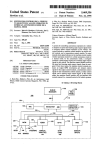
DISPLAYADAPTER
111""
was)
MAIN
159
OUTPUT
DEVICE(S)
E
‘6°
PROCESSOFKS) ‘
ADAPTER
ADAPTER
‘ PROCESSOR(S)
MEMORY
Q
E
a
Q
11
I
7
v
FRAME
BUFFER
MAIN
2_4g
MEMORY
LUT
<->
245
—
l
1_go_
DAC
2i)
E
2Q
7
OUTPUT
DEVlCE(S)
US. Patent
Nov. 21, 1995
Sheet 1 of 9
5,469,275
PRIOR ART
FIG. 1A
100
OUTPUT
PRIOR ART
FIG. 1B
US. Patent
Nov. 21, 1995
Sheet 2 of 9
5,469,275
100
OUTPUT
PRIOR ART
FIG. 1C
OUTPUT
PRIOR ART
FIG. 2
US. Patent
Nov. 21, 1995
Sheet 3 of 9
5,469,275
I
OUTPUT
PRIOR ART
FIG. 3
A
100
R3
H2
80 -
U
R1
D3
R4
60
%
OUTPUT
RED
4o
20E
0
FIG. 6F
R0
l
I
20
4o
|
60
so
>
US. Patent
Nov. 21, 1995
Sheet 4 of 9
5,469,275
am
53;?
E5:2 @mEo9w52QE
AQla
QINN
my5A&l3v
wszE
2:
.52
I@555v H
5:8 @85
a
§I
z_<_=
%aEomwuoE 5Q:&8
@A5 0
93 mm
>
>5 :
m?
9H
6E
q
US. Patent
Nov. 21, 1995
Sheet 5 of 9
5,469,275
100
60
%
OUTPUT
40
100
R3
%
60'
RED
OUTPUT
40 -
R2
US. Patent
OUTPUT
OUTPUT
Nov. 21, 1995
Sheet 6 of 9
5,469,275
US. Patent
Nov. 21, 1995
Sheet 7 of 9
5,469,275
100—
OUTPUT
100
%
OUTPUT
FIG. 6E
US. Patent
Nov. 21, 1995
5,469,275
Sheet 8 of 9
LOAD IMAGE INTO FRAME BUFFER
AND COLOR PALETTE INTO LUT
/ 30°
WHICH COLOR BEING ADJUSTED
f 305
WHAT POINT BEING MOVED
f 310
HOW FAR IS POINT MOVED
f 320
l
CALCULATE POINTS LOCATION
330
f
340
OTHER
POINTS MOVE
'2
CALCULATE POINTS LOCATION
f
350
——-—>
REGENERATE sPLINE
f
l
MODIFY COLOR PALETTE
I
LOAD PALETI'E INTO
DISPLAY ADAPTER LUT
FIG. 7
360
370
_ f
f
380
US. Patent
Nov. 21, 1995
Sheet 9 0f 9
FIG. 8
ALL
RED
WHITE
LIGHT
GRAY
DARK
BLACK
FIG. 9
GREEN
BLUE
5,469,275
5,469,275
1
2
METHOD AND APPARATUS FOR
contains material which is subject to copyright protection.
dashed lines shown in FIG. 1B. Many systems also allow for
the brightness control of each color to be modi?ed sepa
rately. The contrast of the image may also be modi?ed as
shown in FIG. 1C. The contrast control modi?es the slope of
the grayscale relationship to achieve the desirable contrast.
The copyright owner has no objection to the facsimile
reproduction by anyone of the patent document or the patent
Several software tools exist for selectively adjusting the
grayscale by selectively adjusting points on a grayscale
disclosure, as it appears in the Patent and Trademark Office
patent ?le or records, but otherwise reserves all copyright
spline. A spline is a set of points that are interconnected by
some form of interpolation such as straight line, Bezier or
GRAYSCALE ADJUSTMENT
A portion of the disclosure of this patent document
rights whatsoever.
10
vides 11 points that can be adjusted for each color with
straight lines linking the 11 points. FIG. 2 illustrates a
grayscale spline for the color red with the 11 points that can
RELATED PATENT APPLICATIONS
This patent application is related to patent application Ser.
No. 07/925,340 ?led Aug. 4, 1992, and issue date Jun. 7,
1994, US. Pat. No. 5,319,742 (IBM internal Docket No.
AT9-92-090), entitled “PALETTIZED FUZZY MASK”,
hereby incorporated by reference, and to patent application
be adjusted. The user may move any one of the 11 points for
this color and the system will then draw straight lines linking
the moved point with the adjacent nonmoving points. This is
shown in FIG. 2 as dashed lines as the 40 percent input point
is set to 35 percent output. The user may also move any of
Ser. No. 08/403,111, ?led Mar. 13, 1995 which is a con
tinuation of Ser. No. 07/925,712 ?led Aug. 4, 1992 (IBM
internal Docket No. AT9-92-09l), entitled “METHOD AND
APPARATUS FOR LINEAR COLOR PROCESSING”,
20
for the color blue and the color green. As a result of the
by the user.
25
The present invention relates to image processing and
more particularly to selectively adjusting the grayscale.
utilize RGB (red green blue) techniques wherein color
information is processed as three separate digital units of
color information for each displayed pixel. For example, in
a typical 24 bit RGB computer system, 8 bits describe the
Another example is Photoshop which initially provides a
straight line grayscale spline for each color. As shown in
FIG. 3, the user may select a point on the blue spline, from
the 42 percent input level in the illustrated case, and move
it, to the 23 percent level output level in this case. The
BACKGROUND ART
Many methods for displaying color information on dis
play devices are known in the art. Most computer systems
the other 10 points individually to provide the desired
grayscale spline. The same process may also be performed
modi?cations to the grayscale spline, an image rendered
using the grayscale spline will re?ect the changes selected
hereby incorporated by reference.
TECHNICAL FIELD
parametric techniques. For example, Picture Publisher pro
30
system then redraws the blue grayscale spline using a Bezier
curve, shown as a dashed line in FIG. 3. The user may select
and move another point on the blue grayscale spline which
is then redrawn again as a Bezier curve through each of the
selected points. This process continues one point at a time
35
until the desired grayscale spline for the blue color is
achieved. The same process may also be performed for the
intensity or brightness of a red color gun of a display, 8 bits
describe the intensity of a green color gun of the display, and
8 bits describe the intensity of a blue color gun of the display
for a total of over 16 million possible colors for each
color red and the color green.
One problem with the above prior art techniques is that
the user needs to have a detailed understanding of the
displayed pixel.
relationships between color intensities and colors and the
impact of changes of a grayscale spline on a ?nal image.
Otherwise, the user will probably have to perform a large
amount of experimentation in order to obtain the desired
In image processing, frequently an image will be too dark,
too red, too green or have some other defect which will
require an image processing operation to be uniformly
applied over the entire image. For example, a user such as 45 effects on an image.
an artist might want to increase the red of a portrait to
enhance a skin tone. The user may be able to accomplish this
DISCLOSURE OF THE INVENTION
using a technique grayscale adjustment.
Grayscale adjustment is a technique wherein the intensity
or brightness of each of the three color components of pixels
may be adjusted to modify the brightness, color and/or
contrast of an image (including a graphics image, a still
photograph, video or the like). One of the simplest and best
known techniques is shown in FIGS. 1A-1C. A display may
have an input to output relationship for each color, herein
The present invention includes a method for adjusting a
50
for an output device including the steps of adjusting a
location of a ?rst point previously located on the grayscale
spline, adjusting a location of at least one other point,
previously located on the grayscale spline, based on the
55
adjusted location of the ?rst point, generating a grayscale
spline through the ?rst point and the at least one other point,
and producing an image with the output device using the
generated grayscale spline. In addition, the present invention
includes an apparatus for adjusting a grayscale spline,
60
de?ned by a set of interconnected points, for an output
device including an apparatus for adjusting a location of a
after referred to as a grayscale, as shown in FIG. 1A. Of
course, other images, displays or other types of devices such
as printers or plotters may have other possible grayscales. A
simple brightness control may increase the overall bright
ness of all colors simultaneously as shown in FIG. 1B. Note,
however, that greater than 100 percent or white output is
often not possible and increasing the brightness of the
overall image results in brightness saturation for a larger
number of input values. This saturation is shown in the ?at
grayscale spline, de?ned by a set of interconnected points,
?rst point previously located on the grayscale spline, an
apparatus for adjusting a location of at least one other point,
previously located on the grayscale spline, based on the
adjusted location of the ?rst point, and an apparatus for
line 10 at the 100 percent or white output value in FIG. 1B. 65
generating a grayscale spline through the ?rst point and the
However, if greater than 100 percent or white output is
at least one other point.
possible for a given device, then the result would be the
5 ,469,275
3
4
A further understanding of the nature and advantages of
the present invention may be realized by reference to the
software which is executed by the main processor. As would
be obvious to one of ordinary skill in the art, the present
technique could be applied in many other locations within
the host computer or display adapter. For illustrative pur
poses, the present invention is described below utilizing a 24
bit RGB color system (8 bits each for red, green, and blue
color component) with an 8 bit frame buffer, a 256 color
remaining portions of the speci?cation and the drawings.
BRIEF DESCRIPTION OF THE DRAWING
FIGS. 1A-1C illustrate a grayscale with the brightness
and the contrast adjusted;
FIGS. 2 and 3 illustrate grayscale splines modi?ed using
prior art techniques;
video Look Up Table (LUT), and a 640x480 display.
10
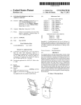
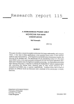
FIG. 4 is a block diagram of a typical digital computer
utilized by a preferred embodiment of the invention;
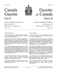
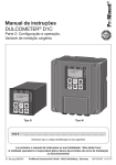
FIG. 5 illustrates a grayscale spline that may be modi?ed
FIG. 5 illustrates a grayscale spline that may be modi?ed
according to the present invention. Initially, in the preferred
embodiment, the grayscale spline for each of the colors is a
straight line. Shown are ?ve points for each color that may
be adjusted according to the present invention. In the pre
ferred embodiment these ?ve points for red are R0 for a 0%
according to the present invention;
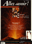
FIGS. 6A—6F illustrate adjusting the grayscale spline for
the color red according to the present invention;
or black shade of red, R1 for a 20% or dark gray shade of
red, R2 for a 50% or middle gray shade of red, R3 for an
80% or light gray shade of red and R4 for a 100% or white
FIG. 7 is a ?owchart illustrating a method for generating
shade of red. The ?ve points for blue and green are at the
a grayscale spline for a given image according to the present
same locations in the preferred embodiment. Each of these
invention;
20
points are connected by a spline which will be described in
FIG. 8 illustrates the keys on a typical QWERTY key
greater detail below. In the preferred embodiment, each of
board that may be used to modify the location of points on
the colors may be individually modi?ed or all the colors may
a grayscale spline; and
be modi?ed simultaneously. For illustrative purposes, modi
FIG. 9 provides a visual readout and input mechanism for
?cation of the color red grayscale spline will be shown in
25
each of the points on the grayscale spline.
FIGS. 6A-6F.
FIG. 6A illustrates the grayscale spline for the color red
BEST MODE FOR CARRYING OUT THE
prior to modi?cation. FIG. 6B illustrates modifying the
INVENTION
white level or R4 by moving it downwards to aifect overall
FIG. 4 is ablock diagram of a typical digital computer 100 30 brightness of the image without affecting the black point R0.
utilized by a preferred embodiment of the invention. The
Accordingly, in the preferred embodiment, any change in R4
will need to affect the other variables except for R0. As
computer, preferably one in the IBM multimedia PS/2 series
of computers, includes main processor(s) 110 coupled to a
shown in FIG. 6B, as the R4 value is decreased by amount
D4, all of the remaining points also are automatically
main memory 120, input device(s) 130 and output device(s)
140. Main processor(s) 110 may include a single processor 35 decreased except for the black or R0 level. The white level
or multiple processors. Main processor is preferably one of
adjustment thus becomes comparable to a brightness adjust
ment, one of the most basic and simple of all controls. Table
the Intel family of 8088, 286, 386 or 486 microprocessors.
1 illustrates code that can be used to modify the R4 level.
However, other microprocessors may be utilized such as the
Motorola family of 68000, 68020 or 68030 microprocessors,
or one of the various Reduced Instruction Set Computer 40
(RISC) microprocessors manufactured by IBM, Hewlett
(c) Copyright International Business
Machines Corp. 1992 All Rights Reserved
This code lowers R4 (white shade of red)
Packard, Sun, Motorola and others. Input device(s) 130 may
include a keyboard, mouse, tablet or other types of input
devices. Output device(s) 140 may include a text monitor,
plotter, printer or other types of output devices. The main
processor may also be coupled to display output device(s)
150 such as a graphics display through a display adapter
45
by a relative amount called d4. d4 is a
measure of distance on a 0 to in?nity scale
that is proportional to D4 shown on
FIG. 613 where d4 ': l—l/(l+D4).
(Note: To raise R4, change all / to * )
R3, R2 and R1 also change, R0 is unaltered.
200. Display adapter 200 receives instructions regarding
graphics or display information from main processor 110 on
bus 160. The display adapter then executes those instruc
tions with display adapter processor(s) 220 coupled to a
TABLE 1
50
R4=(R4—RO)/(l .+d4)+R0;
R3=(R3—R0)/(l .+d4)+RO;
R2=(R2—RO)/(l .+d4)+RO',
Rl=(Rl—RO)/(l.+d4)+R0;
display adapter memory 230. Some display adapters may
not include a processor. The display processors in the
display adapter then execute those instructions and updates
frame buffer(s) 240 and video look up table (LUT) 245
based on those instructions. Display processor(s) 220 may
also include specialized rendering hardware for rendering
speci?c types of primitives to be rendered. Frame buffer(s)
240 includes an index value for every pixel to be displayed
on the display output device. The index value read from the
frame bu?cer is used to read LUT 245 for the actual color to
FIG. 6C illustrates modifying the black level or R0
following the same approach. Moving R0 or black level by
55
be used to modify R0 and the related points R1—R3.
TABLE 2
60
be displayed. A DAC (digital-to-analog converter) 250 con
ment technique could be utilized in the computer application
(c) Copyright International Business
Machines Corp. 1992 All Rights Reserved
This code raises R0 (black shade or red)
verts the digital data stored in the LUT into RGB signals to
be provided to the display 150, thereby rendering the desired
image output from the main processor.
In the preferred embodiment, the grayscale spline adjust
amount D0 also causes R1, R2 and R3 to move as well
without causing R4 to move. Table 2 illustrates code that can
by a relative amount d0 ': l—l/(l+DO)
(Note: To lower R0, change all * to / )
65
5,469,275
5
6
TABLE 2-continued
TABLE 3-continued
The gray or R2 level may also be adjusted in combination
with R1 and R3. This is used as a kind of contrast control
called gamma. It can make the picture dark and moody or
light and airy and can change the color of an image without
FIG. 6E and F illustrate modifying the controls for the
dark gray and light gray independently. The darkened gray
harshly affecting highlights or shadows. Having adjusted the
white level and black level according to saturation limits, it
is usually preferable to leave them alone. Adjusting R2 will
never saturate or unsaturate any white or black. As shown in
FIG. 6D, when the gray level R2 is moved by amount D2,
then the R1 and R3 values are also modi?ed accordingly in
the preferred embodiment. Table 3 illustrates code that can
be used to modify R2 and the related points R1 and R3.
The formulas used in the code in Table 3 aim the middle
gray, do not affect the white R4 or black R0, and vary light
R3 and dark gray R1 proportionately. Middle gray of a
15
by R0 and R2.
TABLE 4
straight line is affected as much per incremental change as
white was per incremental change in the example of Table
1. R2 is raised by D2*l00 percent of R4-R0 when R2 is
midway between R0 and However the effect is proportional
25
First, ?nd tl=(R2—R0)/(R4—R2). t1 points to the position
multiplied or divided by any positive number without it
going out of it’s 0 to in?nity range. Thus, t1 is multiplied by
(1+4d2) to step it by the d2 step size. Next, calculate
t2=(tl*R4+R0)/(tl+l.). This formula undoes what the ?rst
formula did, so nominally t2 would equal to R2 as presented
so far. In the last line of Table 3, R3 gets set to t2. It is
30
The light gray control R3 alters the contrast of extreme
highlights to pick out detail in overexposed slides or tint
splashes of sunlight. Table 5 illustrates code that can be used
to modify R3.
maintained separate before then so the old and new value
can enter into other calculations. However, in the program t1
TABLE 5
(c) Copyright International Business
is also multiplied by (l.+4*d2) so t2 gets increased. The
“4*” gives the same percentage increase as previously
presented for R0 and R4 if R2 is exactly midway between
R0 and R4. But if the grayscale line is skewed, these
formulas reduce the amount of change so it is proportioned
to keep t2 within the desired range. The division, rather than
Machines Corp. 1992 All Rights Reserved
This code raises R3 (light gray) by a amount d3.
The code operates in nonlinear space so R3 can
never be greater than R4 or less than R2.
an addition in the matching reduction statement makes this
process reversible with the same number of strokes in the 45
other direction.
The logic begins similarly to calculate R1 by translating
it into the zero to in?nity range. The translation into the
skewed range uses R2, while the translation out uses the
revised t2, so the ?rst order correction is automatic. Beyond
that it describes a bounded parabola The 20% point needs to
move 0.64 of the 50% point. 0.40 will be automatic by the
second order nature of a parabola, so 0.24 more is needed.
Thus the 1+d2 term becomes pow(t3,0.24*4.) where t3 is the 55
relative movement of the R2 point.
TABLE 3
\*
(c) Copyright International Business
Machines Corp. 1992 All Rights Reserved
This code raises R2 (middle gray) by a
relative amount :12 '= l—l/(l+d2)
(Note: To lower R2 by a relative delta,
R1 and R3 also change, R0 and R4 are
*\
(c) Copyright International Business
Machines Corp. 1992 All Rights Reserved
This code raises Rl (dark gray) by amount d1.
(To lower R3, change *(1.+4.*dl) to /(1.+4.*d1))
The code operates in nonlinear space so Rl can
never be greater than R2 or less than R0.
so gray can not surpass white R4 or black R0.
of gray R2 relative to black R0 and white but cast in a
function that varies between 0 and in?nity so it can be
control. R1 controls the contrast of the shadows to pick out
detail from images that were underexposed or control
shadow color independent of the rest of the image. Table 4
illustrates code that can be used to modify R1. As before, t1
takes R1 into a domain that varies from zero to in?nity
between R0 and R2, such that multiplying or dividing by any
?nite positive number will not take it beyond the limits set
60
As mentioned before, these sections of code expressed for
red, would normally be repeated for green and blue, result
ing also in the variables G0, G1, G2, G3, G4, B0, B1, B2,
B3, and B4.
As the various points on the grayscale are moved, a spline
needs to be run through the 5 points corresponding to each
of the 3 colors to provide a continuous grayscale curve for
each color for use in splining the image for all grayscale
points in an image. A spline is an interpolation technique that
typically forms a continuous line through a given set of
points. However, a spline may also comprise a large number
of discrete points that appear to form a line through a given
set of points. Many spline functions exist to run a smooth
curve through 5 points such as using a 4th order polynomial
or using a Bezier curve. However, it is preferred that the
spline be monotonic positive (upward sloping at all points)
so no part of the grayscale goes into a negative slope. A
simple 4th order polynomial fails this such that under even
65
moderate adjustment of the gamma variable R2 giving
solarized highlights or shadows. The eye is also very sen
sitive to the ?rst derivative of the curve. This ?rst derivative
5,469,275
8
7
determines the graininess and detail of any level of grayscale
and therefore the ?rst derivative must be a smoothly varying
continuous variable. Finally, the extreme points must main
tain reasonable contrast, thus certain end point assumptions
commonly made by spline algorithms do not work well. The
contiguous code shown in Tables 6A and 6B below solves
these problems by operating in the ?rst derivative, or slope,
domain. That is, the slope of the spline is always monotonic.
This is accomplished by careful selection of slopes at each
point on the spline and possibly at some intermediate points.
These points are then splined with polynomial curves. Such
TABLE 6B-continued
The techniques for generating the grayscale spline accord
ing to the present invention involve having relationships
a function is extremely important to extend a manageable set
of variable points along a grayscale spline to a smoothly
continuous grayscale spline for image translation.
15
TABLE 6A
between the points on the grayscale curve. That is, when one
point is moved, other points are also moved at the same time.
By providing these relationships, a more user friendly sys
tem is made available that allows a user to achieve the
(c) Copyright International Business
Machines Corp. 1992 All Rights Reserved
Receive the gray scale aim points, return
translation array.
desired results more readily. In addition, the ?exibility of the
grayscale spline is maintained for detailed modi?cation. In
20
translate(nco1inc,R0,Rl,R2,R3,R4,transr)
?oat RO,Rl,R2,R3,R4,transr[256];
int ncolinc;
{
?oat x,xx,yy,tr;
?oat xxa[ l l],yya[ l 1],sa[2l ],xa[2l],ya[2l ],qa[2l_];
int n,na,ix,iy;
copy in xxal ] and yya[ 1. Note xxa and yya are
the only arrays that count in double steps.
xxa[0]=.0;
xxa[4]=l.;
xxa[l]=.2;
na=5;
xxa[2]=.5;
yya[0]=R0;
yya[2]=R2;
yya[3]=R3;
yya[4]=R4;
Calculate slopes at input nodes as the reciprocal
of the average of reciprocals of the slopes to
the lower and higher nodes. This limits the
slope to less than twice the segment slope so the
25
will cause R1 and R3 to move. In alternative embodiments,
as one of ordinary skill may appreciate, more or fewer points
may be used (or may be user de?ned). In addition, the user
may be able to de?ne the hierarchy or other type of rela—
tionship between the points by use of a table or other
30
relationship de?ning mechanism.
As one of ordinary skill can readily appreciate, the present
invention may also be utilized to adjust the grayscale spline
intermediate node slope need never be negative.
for(n=l; n<=na—2; n-H-)
sa[n*2]=
2./(l ./((yya[n]—yya[n—l ])/(xxa[n]—xxa[n-—l 1))
+1 ./((yya[n+l ]-—yya[n])l(xxa[n+l ]—xxa[n])));
the preferred embodiment with 5 de?ned points on the curve
that can be moved, the points have a hierarchical relation
ship wherein R0 and R4 are at the top of the hierarchy, R2
is at the middle, and R1 and R3 are at the bottom of the
hierarchy. In the hierarchy, moving R0 or R4 will cause R1,
R2 and R3 to move at the same time. In addition, moving R2
35
Calculate slopes at end nodes as 2*segment slope
minus internal node slope. Because of limits on
the previous calculation of the internal node
slope, this can never be zero.
sa[0l=2-*(yya[1l—yya[0l)/(XXa[1l—XXa[0l)-Sa[2l;
salna*2—2]=2.*(yya[na—l-]—yya[na—2])/
(xxa[na-—l]—xxalna—2])—sa[2*na—4];
continued in Table 6B
for a printer, plotter or other type of output device.
FIG. 7 is a ?owchart illustrating a preferred method for
generating a grayscale for a given image. Before the color
enhancement process is exercised, the user loads an image
to be processed into a display adapter using a color palette,
and loads the color palette associated with the image into the
LUT in step 300. Now in exercising the process, in a ?rst
step 305, it is determined whether the user is selecting a
particular color or all colors simultaneously. If all colors are
selected, then corresponding points for each of the colors
will be moved concurrently on the grayscale curve. In a
45
second step 310, it is determined what point on the grayscale
spline the user has selected. In a third step 320, it is
determined the direction and magnitude of movement the
user has requested. This is preferably determined on a
proportional basis wherein the user indicates a percentage of
movement toward a particular direction (e.g. 10 percent of
the distance towards a limit for that point). This allows the
user to move a particular direction in continually decreasing
increments while specifying the same percentage, as the
TABLE 6B
limit is approached. In a fourth step 330, the point’s location
55
on the grayscale is calculated from the user indications. In
a-?fth step 340, it is determined whether any other points
also should be moved relative to the movement of the user
selected point. This may be accomplished by hardcoding the
relationship into the code performing this function or the
user may de?ne or prede?ne the point relationships in a table
or the like. In a sixth step 350, the location of the other points
location on the grayscale is calculated. In a seventh step 360,
the spline is regenerated for the grayscale. In an eighth step
370, a color palette for storage in a LUT is generated by
65
applying the three color grayscale splines to each palette
color in the unprocessed palette associated with the image
being displayed. This is performed using well known tech~
5,469,275
10
oversaturated points in another color such as 100% white,
and all undersaturated points in another color such as 0%
black. When Combined with full color, this display may
apply separately to each of the three colors. For example, a
pixel with over saturated red, undersaturated blue, and
niques including gamma distribution of the palette colors on
the grayscale (a nonlinear distribution based on the human
eye’s perception of colors). In a ninth step, the color palette
is loaded into the LUT of the display adapter so the new
grayscale splines are applied to the image being displayed.
In the preferred embodiment, this process is performed as
unsaturated green would display as 100% red, 0% blue, and
50% green, producing a bright orange. This is accomplished
in the process by receiving the grayscale spline calculated
according to the invention presented above, leaving 0% and
l00%'points unaffected, and reducing all other points to
50%. Another useful feature, particularly in conjunction
with the display of saturation is to receive the palette as
quickly as feasible to provide quick feedback to the user.
Ideally, the user should not be aware of any time lag between
modifying the grayscale spline and the image being dis
played being modi?ed based on the grayscale spline modi
?cations.
Several techniques may be used for the user to specify
changes to points on each of the color grayscale splines. For
calculated from the grayscale spline adjusted by this inven
example, the user may use the keys on a typical QWERTY
keyboard as shown in FIG. 8. The 1, 2, 3, 4, and 5 keys may
be used to specify increasing the ?rst through ?fth points,
respectively, on the blue grayscale spline. The q, w, e, r, and
t keys may be used to specify increasing the ?rst through
?fth points, respectively, on the green grayscale spline. The
a, s, d, f, and g keys may be used to specify increasing the
?rst through ?fth points, respectively, on the red grayscale
tion, but load into the LUT selectively either the full color,
15
20
increasing the ?rst through ?fth points, respectively, for all
that the particular point be decreased. In addition, each time
a key is pressed, then the point indicated by that key is
moved upwards or downwards (including any related points)
in the grayscale. For example, if the (1 key is pressed, then
the third point on the red grayscale spline is move upwards
towards saturation by an increment and the second and
is de?ned by the appended claims.
25
location adjustable by a user through a user interface, for an
30
ment through said user interface, a location of a ?rst
ously located on said grayscale spline, based on the
adjusted location of the ?rst point;
c) generating a grayscale spline through said ?rst point
wards and the second and fourth points also move down~
and said at least one other point; and
wards slightly. This process may be performed while the
d) producing an image with said output device using said
image, video or the like having its grayscale spline adjusted
is being displayed, providing for good concurrent feedback
generated grayscale spline.
to the user.
Another technique that may be used for the user to specify
changes to points on each of the color grayscale splines is
shown in FIG. 9. This is a visual readout of each of the
points on the grayscale that may be displayed over a portion
of the image or may be displayed in a separate part of the
display such as in a separate window. In this example, the
user indicates which point is to be moved by clicking a
mouse while a cursor is over the readout for that point. The 50
user then moves the cursor upwards or downwards with the
mouse to indicate the amount of movement of the point on
the grayscale. As this is done, the image may be continually
updated by the computer system to show the visual impact
points on the grayscale splines may also be moving upwards
niques. The system will then display the image with all
nonsaturated points in one color such as 50% gray, all
output device comprising the steps of:
a) adjusting, responsive to user input of a location adjust
point previously located on said grayscale spline;
b) adjusting a location of at least one other point, previ
slightly. If the d key is pressed again, then the third point on
the red grayscale spline is moved upwards again and the
second and fourth points also move upwards slightly again.
If the shift key is pressed concurrently with the d key, then
the third point on the red grayscale spline is moved down-l
or downwards concurrently with the selected point.
In the preferred embodiment, the user may also request
that the computer system display which points on the image
being displayed are saturated or undersaturated. This may be
activated 'or deactivated by pressing a certain key on the
keyboard, by selecting a speci?ed region in a window
providing that option, or other commonly known tech
What is claimed is:
1. A method for adjusting a grayscale spline, de?ned by a
set of interconnected points, each of said points having a
fourth points on the red grayscale curve are also moved up
of the movement of the point. In addition, the readout of the
point may also be continually updated to indicate the loca
tion of the point on the grayscale. Furthermore, other related
rately each of the three color records of the image processed
by this invention.
Although the present invention has been fully described
above with reference to speci?c embodiments, other alter
native embodiments will be apparent to those of ordinary
skill in the art. Therefore, the above description should not
be taken as limiting the scope of the present invention which
spline. The z, x, c, v, and b keys may be used to specify
the grayscale splines at the same time. By pressing shift and
any one of the keys speci?ed above, then that may specify
or load a select one of the three colors to all three color
entires in the LUT. This effectively lets a user view sepa
55
2. The method of claim 1 wherein said step of generating
includes generating a continuous grayscale spline.
3. The method of claim 2 wherein said step of generating
includes generating a monotonic grayscale spline.
4. The method of claim 3 wherein said step of generating
includes generating a monotonic grayscale spline in a ?rst
derivative domain.
5. The method of claim 1 wherein said step of adjusting
said location of said at least one other point includes
adjusting said location of said at least one other point based
on a hierarchical relationship with said ?rst point.
6. The method of claim 5 wherein said step of adjusting
the location of the ?rst point includes receiving signals from
a keyboard indicating the adjustment of the location of said
?rst point.
7. The method of claim 5 wherein said step of adjusting
the location of the ?rst point includes receiving signals from
a display user interface indicating the adjustment of the
location of said ?rst point.
8. The method of claim 5 wherein said step of producing
an image includes producing an image with a display.
9. The method of claim 5 wherein said step of producing
an image includes producing an image with a printer.
10. The method of claim 5 wherein said step of producing
65 an image includes producing an image with a plotter.
11. An apparatus for adjusting a grayscale spline, de?ned
by a set of interconnected points, each of said points having
5 ,469,275
11
12
a location adjustable by a user through a user interface, for
said program code means for generating includes program
code means for generating a monotonic grayscale spline in
an output device comprising:
a) means for adjusting, responsive to user input of a
location adjustment through said user interface, a loca
tion of a ?rst point previously located on said grayscale
a ?rst derivative domain.
26. The computer program product of claim 22 wherein
said program code means for adjusting said location at said
at least one other point includes program code means for
spline;
adjusting said location of said at least one other point based
on a hierarchical relationship with said ?rst point.
b) means for adjusting a location of at least one other
point, previously located on said grayscale spline,
based on the adjusted location of the ?rst point; and
27. The computer program product of claim 26 wherein
0) means for generating a grayscale spline through said
said program code means for adjusting the location of the
?rst point and said at least one other point.
12. The apparatus of claim 11 wherein said means for
generating includes means for generating a continuous gray
?rst point includes program code means for receiving sig
nals from a keyboard indicating the adjustment of the
location of said ?rst point.
28. The computer program product of claim 26 wherein
scale spline.
13. The apparatus of claim 12 wherein said means for
generating includes means for generating a monotonic gray
15
scale spline.
14. The apparatus of claim 13 wherein said means for
generating includes means for generating a monotonic gray
scale spline in a ?rst derivative domain.
15. The apparatus of claim 11 wherein said means for
adjusting said location of said at least one other point
includes means for adjusting said location of said at least one
other point based on a hierarchical relationship with said
20
said program code means for adjusting the location of the
?rst point includes program code means for receiving sig
nals from a display user interface indicating the adjustment
of the location of said ?rst point.
29. The computer program product of claim 26 wherein
said program code means for producing an image includes
program code means for producing an image with a display.
30. The computer program product of claim 26 wherein
said program code means for producing an image includes
25
?rst point.
program code means for producing an image with a printer.
16. The apparatus of claim 15 wherein said means for
31. The computer program product of claim 26 wherein
adjusting the location of the ?rst point includes means for
said program code means for producing an image includes
receiving signals from a keyboard indicating the adjustment
program code means for producing an image with a plotter.
of the location of said ?rst point.
32. A data processing system for adjusting a grayscale
17. The apparatus of claim 15 wherein said means for
spline, de?ned by a set of interconnected points, each of said
adjusting the location of the ?rst point includes means for
points having a location adjustable by a user through a user
receiving signals from a display user interface indicating the
adjustment of the location of said ?rst point.
18. The apparatus of claim 15 further comprising an
output device for producing an image using said generated
35
grayscale spline.
19. The apparatus of claim 18 wherein said output device
includes a display.
20. The apparatus of claim 18 wherein said output device
includes a printer.
21. The apparatus of claim 18 wherein said output device
includes a plotter.
22. A computer program product executable by a proces
sor for adjusting a grayscale spline, de?ned by a set of
interconnected points, each of said points having a location
40
scale spline, based on the adjusted location of the ?rst
point; and
45
means for generating includes means for generating a con
a) program code means for adjusting, responsive to user
input of a location adjustment through said user inter
face, a location of a ?rst point previously located on
tinuous grayscale spline.
34. The data processing system of claim 33 wherein said
said grayscale spline;
means for generating includes means for generating a mono
tonic grayscale spline.
b) program code means for adjusting a location of at least
one other point, previously located on said grayscale
35. The data processing system of claim 34 wherein said
55
means for adjusting said location of said at least one other
point includes means for adjusting said location of said at
60
23. The computer program product of claim 22 wherein
least one other point based on a hierarchical relationship
with said ?rst point.
said program code means for generating includes program
code means for generating a continuous grayscale spline.
24. The computer program product of claim 23 wherein
said program code means for generating includes program
code means for generating a monotonic grayscale spline.
25. The computer program product of claim 24 wherein
means for generating includes means for generating a mono
tonic grayscale spline in a ?rst derivative domain.
36. The data processing system of claim 32 wherein said
and
(1) program code means for producing an image with said
output device using said generated grayscale spline.
e) means for generating a grayscale spline through said
?rst point and said at least one other point.
33. The data processing system of claim 32 wherein said
>
spline, based on the adjusted location of the ?rst point;
0) program code means for generating a grayscale spline
through said ?rst point and said at least one other point;
b) a memory for storing data to be processed;
c) means for adjusting, responsive to user input of a
location adjustment through said user interface, a loca
tion stored in memory of a ?rst point previously located
on said grayscale spline;
d) means for adjusting a location stored in memory of at
least one other point, previously located on said gray
adjustable by a user through a user interface, for an output
device comprising:
interface, for an output device comprising:
a) a processor for processing data;
65
37. The data processing system of claim 36 wherein said
means for adjusting the location of the ?rst point includes
means for receiving signals from a keyboard indicating the
adjustment of the location of said ?rst point.
38. The data processing system of claim 36 wherein said
5,469,275
13
14
means for adjusting the location of the ?rst point includes
means for receiving signals from a display user interface
output device includes a display.
.
41. The data processing system of claim 39 wherein said
indicating the adjustment of the location of said ?rst point.
39. The data processing system of claim 36 further
comprising an output device for producing an image using
output device includes a printer.
42. The data processing system of claim 39 wherein said
output device includes a plotter.
said generated grayscale spline.
40. The data processing system of claim 39 wherein said
*
*
*
*
*