1
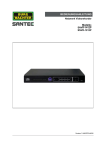
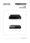
USER MANUAL Network Video Recorder Models: SNVR-1412P SNVR-1812P Version 1.1sfi/0615/engl/A5 Dear customer, Thank you for purchasing a high quality SANTEC device. We recommend that you read this manual thoroughly before operating your new system for the first time. Please follow all instructions and observe the warnings contained in this manual. Please contact your local dealer or SANTEC directly if you have any questions or if you wish to claim for a service or warranty. You will find further information on our website: www.santec-video.com Imprint: All rights reserved. This publication may not be reproduced, stored in a retrieval system or transmitted, in any form or by any means (electronic, mechanical, photocopying, recording or otherwise), without the written prior permission of SANTEC BW AG. No reproduction of any part or excerpts thereof are permitted. Errors excepted. Specifications are subject to change without notice for quality improvement. SANTEC is a registered trademark of SANTEC BW AG. All other companies or products mentioned in this publication are trademarks, registered trademarks or brands of the respective company. © Copyright: SANTEC BW AG An der Strusbek 31 22926 Ahrensburg Germany www.santec-video.com User manual SNVR-1412P, SNVR-1812P Table of contents 1. General 1.1 Security notes and safety precautions 1.2 CE compliance 1.3 Important general notes 1.4 Items included in the delivery 1.5 „Burg Cam“ App for P2P applications 1.6 General notes 5 5 5 6 7 8 8 2. Controls, indicators and connectors 2.1 Front view 2.2 Connections on recorder rear 9 9 11 3. Quick start 3.1 Getting started 3.2 Login 3.3 Calling-up the main menu 3.4 Changing the menu language 3.5 Logout and switching the recorder off 12 12 12 13 13 13 4. Notes on connected cameras 13 5. Controlling the recorder 5.1 Controlling the recorder using the mouse 5.2 Controlling the recorder using the IR remote control 14 14 15 6. Live view 6.1 Event display 6.2 Calling-up the menu bar 6.3 Calling-up the quick menu using the right mouse button 6.3.1 View 6.3.2 PTZ control 6.3.2.1 overview 6.3.2.2 Aux configuration 6.3.2.3 Aux 6.3.3 Auto focus 6.3.4 Camera 6.3.5 Search 6.3.6 Manual 6.3.7 Remote device 6.3.8 Main menu 6.4 Calling-up the navigation bar 6.5 USB auto pop-up 16 16 17 18 18 18 18 20 23 23 23 23 23 23 23 24 25 7. Main menu settings 7.1 Main menu Operate Search 7.1.1 Intelligent search 7.1.2 Search by time 7.1.3 Search by mark 7.2 Main menu Operate Backup 7.3 Main menu Operate Shutdown 7.4 Main menu Info 26 27 31 31 32 33 34 35 _________________________________________________________________________________ -3- User manual SNVR-1412P, SNVR-1812P 7.5 Main menu Setting 7.5.1 Main menu Setting Remote 7.5.1.1 Main menu Setting Remote Remote 7.5.1.2 Main menu Setting Remote Camera 7.5.1.3 Main menu Setting Remote Audio/Video 7.5.1.4 Main menu Setting Remote Camera name 7.5.2 Main menu Setting Network 7.5.2.1 Main menu Setting Network TCP/IP 7.5.2.2 Main menu Setting Network Connection 7.5.2.3 Main menu Setting Network PPPoE 7.5.2.4 Main menu Setting Network DDNS 7.5.2.5 Main menu Setting Network UPnP 7.5.2.6 Main menu Setting Network IP filter 7.5.2.7 Main menu Setting Network E-mail 7.5.2.8 Main menu Setting Network FTP setting 7.5.2.9 Main menu Setting Network SNMP 7.5.2.10 Main menu Setting Network Multicast 7.5.2.11 Main menu Setting Network P2P setting 7.5.2.12 Main menu Setting Network Alarm center 7.5.2.13 Main menu Setting Network Register 7.5.2.14 Main menu Setting Network Switch 7.5.3 Main menu Setting Event 7.5.3.1 Main menu Setting Event Detection 7.5.3.2 Main menu Setting Event Alarm 7.5.3.3 Main menu Setting Event Abnormality 7.5.3.4 Main menu Setting Event Alarm-OUT 7.5.4 Main menu Setting Storage 7.5.4.1 Main menu Setting Storage Schedule 7.5.4.2 Main menu Setting Storage HDD 7.5.4.3 Main menu Setting Storage Record 7.5.4.4 Main menu Setting Storage Channel 7.5.5 Main menu Setting System 7.5.5.1 Main menu Setting System General 7.5.5.2 Main menu Setting System Display 7.5.5.3 Main menu Setting System RS-232 7.5.5.4 Main menu Setting System PTZ 7.5.5.5 Main menu Setting System Account 7.5.5.6 Main menu Setting System Auto maintain 7.5.5.7 Main menu Setting System Import/Export 7.5.5.8 Main menu Setting System Default 7.5.5.9 Main menu Setting System Upgrade 35 35 36 37 37 37 38 38 39 39 39 40 41 41 42 42 43 43 43 43 43 44 44 45 46 46 47 47 48 48 48 49 49 51 51 52 52 52 53 53 53 8. Technical specifications 54 9. Remote access: Access the recorder via the web 9.1 Establish a network connection 9.2 Login via the web 9.3 LAN connection 9.3.1 Displayed information in video image 9.3.2 PTZ control 9.4 WAN connection 9.5Additional web connections 55 55 55 57 58 59 61 62 _________________________________________________________________________________ -4- User manual SNVR-1412P, SNVR-1812P 1. General Please read this user manual carefully before starting to operate this device. Please retain this user manual for future reference. 1.1 Safety instructions and precautions Overcharge Never expose the power socket or the power cord to electrical overcharge. This may lead to fire and life-threatening shocks. Thunderstorms If there is a thunderstorm or if the device has not been in use for a longer period of time, please always disconnect the device from the power source. Disconnect the power cord. This protects the device from lightning damages or overcharging. Entry of liquids or items Never poke with metallic items in the ventilation slots of the device. You may touch dangerous live power items which may lead to an electronic shock, a short circuit or fire. Lithium battery Risk of explosion if the lithium battery is not installed correctly or if it is replaced by an incorrect type. Only use batteries which are compatible to the device and are recommended by the manufacturer. Dispose of used batteries only in accordance with local regulations. 1.2 CE compliance This appliance complies with the CE guidelines. If you require an EC Declaration of Conformity for this device, please send a request to: [email protected] Attention: Any changes or modifications to this appliance which have not been explicitly approved of by the respective regulatory authority, may lead to a prohibition of usage of this appliance. Important: Legal note Monitoring, recording and storage of video surveillance data (images, sound), is subject to strict legal regulations. Please respect the Data Privacy Act which applies to your country. _________________________________________________________________________________ -5- User manual SNVR-1412P, SNVR-1812P 1.3 Important general note Please read the following instructions carefully. 1.3.1 Assembly and installation On-site installation should only be performed by qualified maintenance personnel and must meet local specifications and regulations. Never operate the equipment without the respective protective cover near water, in dusty rooms or extremely humid rooms. The equipment could be seriously damaged. The openings on the equipment are intended for ventilation purposes and protect from overheating. Never cover or close off these openings. Rack mounting is only permissible if sufficient ventilation can be ensured. Overheating may damage the equipment or result in fire due to short-circuit. Power cables and other cables should be run so as to avoid being stepped on or potential damage from falling objects. Damaged cables may result in short-circuit and equipment damage as well as potentially fatal electrical shock. When connecting the supply voltage please note correct polarity. Faulty connections may damage or destroy the equipment. Only use the power source specified on the nameplate. Please consult your electrician if you are unsure whether the power supply on site is appropriate. Only use the supplied power cables or power adapters or the specified recommended power supplies. 1.3.2 Maintenance and repair Shut off and unplug the equipment from the power receptacle prior to every cleaning. Only clean the equipment with a slightly dampened cloth. Do not use harsh cleaners or spray cans. Using harsh solvents such as thinner or petrol may damage the housing surface. Immediately shut off the equipment and promptly disconnect it from the operating voltage. The following damages must be handled by an authorized service centre: o Damage to the power supply cable o If a liquid spilled onto the equipment or an object penetrated the equipment o If the equipment was exposed to water or another liquid o If the equipment is not functioning properly despite observing the instructions in these operating instructions. Only the controls specified in these operating instructions may be adjusted. Incorrect settings to the other controls may damage the equipment. o If the equipment fell to the floor or the housing was damaged o If the equipment performance is substantially the required performance Never attempt to maintain the equipment yourself, as this may expose you to hazardous voltages. Maintenance work should always be performed by qualified personnel only. _________________________________________________________________________________ -6- User manual SNVR-1412P, SNVR-1812P Attention: Opening the appliance will result in loss of warranty. Do not try to repair the appliance yourself but contact your local distributor or specialist. For digital recorders, it is mainly the HDD which subject to natural attrition. HDD attrition may happen after approx. 8,000 to 10,000 hours of operating time which may lead to malfunctions. We thus recommend to replace the HDD in specific intervals in order to ensure a smooth operation of the appliance. Moreover, we recommend to clean the built-in fan regularly from dust and dirt to avoid interferences caused by overheating. Please do not hesitate to contact us in case of further questions. Attention: Attrition of mechanical parts We explicitly point out that any type of recording device, no matter if it is an analogue or digital device, is subject to natural attrition. Every recording device contains mechanical parts which – like any other device – need to be maintained and checked regularly. This is particularly important for appliances which run non-stop. 1.3.3 Spare parts and accessories Only use auxiliary devices which are recommended by the manufacturer. Nonrecommended devices may influence the functionality and may cause electric shocks or fire caused by short circuits. Only use spare parts which are recommended by the manufacturer or which have identical characteristics. Non-approved spare parts may cause harm to people (electric shock) and may damage the device (fire). 1.4 Items included in the delivery 1x Recorder SNVR-1412P or SNVR-1812P 1x Mouse 1x CD (Configuration tool, quick installation guide) 2x Power adapter (only for SNVR-1412P) 1x Power cord 2x Terminal blocks 1x IR remote control 1x Quick installation guide and security notes _________________________________________________________________________________ -7- User manual SNVR-1412P, SNVR-1812P 1.5 „Burg Cam“ App for P2P applications Using the “Burg Cam” App, you can call-up and control the device by your smartphone or tablet. The following Apps are available for smartphone and tablets: the a free-of-charge “Lite” version or the “Pro” version with costs. App Name Device Functions Costs System Burg Cam Lite Smartphone Basic functions, e.g. image adjustment, snapshots, local recording Free-of-charge iOS, Android Burg Cam Pro Smartphone Advanced functions, e.g. image adjustment, stream quality, push notification With costs iOS, Android Burg Cam HD Lite Tablet Basic functions, e.g. image adjustment, snapshots, local recording Free-of-charge iOS, Android Burg Cam HD Pro Tablet Advanced functions, e.g. image adjustment, stream quality, push notification With costs iOS, Android You can download these Apps in the respective stores. 1.6 General note Windows, Android, IOS are trademarks or registered trademarks in the USA and in other countries. All other companies or products mentioned in this publication are trademarks, registered trademarks or brands of the respective company. They are not connected in any way with SANTEC BW AG. Proprietary rights are with the respective manufacturers or brand owners. Illustrations and pictures in this user manual are for better understanding only and may differ from the actual product design. All technical specifications are subject to change. Errors excepted. _________________________________________________________________________________ -8- User manual SNVR-1412P, SNVR-1812P 2. Controls, indicators and connectors 2.1 Front panel Indicators on recorder front panel: 1 No. 1 2 3 4 5 6 3 2 Indicator ALARM REC HDD NET ACT POWER 5 4 6 Description Alarm Recording HDD Network connection IR remote control Power Controls on recorder front panel: 1 No. 2 3 4 5 6 7 8 9 10 11 12 Key 1 On/Off/Login 2 IR receiver 13 14 Description 1x push quickly: The login window is displayed. Press and hold for approx. 3 seconds when the recorder is running: The recorder will shut down. 1x push quickly when recorder is not running: The recorder will boot. This will only work if the on/off button on the recorder rear has been set to “on”. Please do not cover. _________________________________________________________________________________ -9- User manual SNVR-1412P, SNVR-1812P 3 Play, Next 4 5 Fast forward Play, Pause 6 REC 7 ESC 8 Back 9 Play slow Reverse, Pause 10 11 SHIFT 12 FN 13 14 Up, down, left, right, Enter USB interface In playback mode, go to the next video. In menu mode, go to the next menu item. Go fast forward Toggle between playback and pause. Go to recording menu. Also see the following chapter:: Main menu Setting Storage Record (see chapter 7.5.4.3) Cancel and go back to previous menu page. In playback mode, go to previous video. In menu mode, go to previous menu item. Slow playback Pause If you want to enter digits/characters in an entry field (as an alternative to the virtual keyboard), you can use the Shift key to toggle between letters and numbers and between small and capital letters. In full screen mode: Press this key to call-up the PTZ setting window. For entry fields: Drücken Sie diese Taste, um die eingegeben Zeichen (Buchstaben, Zahlen) zu löschen. As an alternative of using the mouse, you can use the direction buttons to navigate through the menu. Press “Enter” to confirm your choice. To connect a USB device, e.g. a mouse. _________________________________________________________________________________ - 10 - User manual SNVR-1412P, SNVR-1812P 2.2 Connections on recorder rear SNVR-1412P: 3 7 6 4 11 8 5 10 1 2 9 SNVR-1812P: 1 2 3 6 4 Connection 1 2 3 4 5 6 7 8 9 10 11 5 7 8 10 9 Description Power input: SNVR-1412P: 12V SNVR-1812P: 230V Power on/off PoE connection Network connection VGA connection Microphone input/output RS-232 HDMI USB connection Alarm output, RS-485 Only for SNVR-1412P: 48V connection for PoE supply _________________________________________________________________________________ - 11 - User manual SNVR-1412P, SNVR-1812P 3. Quick start 3.1 Getting started Connect the mouse, the monitor and the camera(s) with the recorder an (also see chapter 4 on notes on cameras). Connect the monitor and the camera to power (power adapters are included in the respective camera delivery) Finally, connect the recorder to power by using the supplied power adapter/power cord. Switch on the recorder by using the on/off power button on the recorder backside. The POWER LED indicator on the recorder front panel lights up in green Depending on your pre-defined settings, either the camera’s live image or the startup wizard is displayed. You can configure the startup wizard here (see chapter 7.5.5.1): Main menu Setting System General Startup Wizard o Startup Wizard: o Click on „Next step“ or „Cancel“ to go to the login page. Live image: Left-click into the live image. The login window is displayed. 3.2 Login Enter your user name and password and confirm with „Save“. By default, the following user name and password are set: User name: admin Password: 9999 Important note: It is recommended to change the user name and password here: Main menu Setting System Account User (to call-up the main menu, see chapter 3.3 and chapter 7) You are now logged in and have access to various functions. Note on wrongly entered login details:: If you enter 3 times a wrong user names or passwords within 30 minutes, an alarm is triggered. If you enter 5 times wrong login detials, your user account will be locked. _________________________________________________________________________________ - 12 - User manual SNVR-1412P, SNVR-1812P 3.3 Calling-up the main menu You have 2 options to call-up the main menu: To open the main menu, right-click into the live image and select „Main Menu“ from the displayed quick menu. Alternatively, you can open the main menu through the navigation bar which is displayed in the live image. This, however, requires that the navigation bar has previously been enabled. You can enable the display of the navigation bar here (see chapter 7.5.5.1): Main menu Settings System General Navigation bar 3.4 Changing the menu language Open the main menu and select the following: Main menu Settings System General Language (see chapter 7.5.5.1) You can choose from English or German. The default language ex factory is German. 3.5 Logout and switching off the recorder Open the main menu and select the following (see chapter 7.3): Main menu Operate Shutdown Alternatively, you can press the on/off/login key on the recorder front panel (see chapter 2.1) to shut down the recorder. The recorder will shut down, but it is still in operation mode (the LEDs on the recorder front panel are still lighting green). To finally switch off the recorder, use the power on/off button at the rear of the recorder. Note: Please always shut down the recorder prior to switching it off (see above) and don’t switch it off while still running. 4. Note on used cameras Only network cameras (IP cameras) can be connected to this recorder and their images be recorded. SANTEC offers a variety of different IP camera models. Please go to our webshop at: www.santec-video.com _________________________________________________________________________________ - 13 - User manual SNVR-1412P, SNVR-1812P 5. Controlling the recorder 5.1 Controlling the recorder using the mouse You can control the recorder using the supplied mouse. Connect the mouse to the USB port on the recorder’s front or rear panel. Single left-click: Use a single left-click to select a menu item or to start entering data. Double left-click: In live mode, double left-click in the respective camera image to display it as full screen. Double left-click again into the full screen to return to the previous split screen. Single right-click: In live mode, single right-click into the live image to open the quick menu. Here you will find the following items: View (see chapter 6.3.1) Pan/Tilt/Zoom (see chapter 6.3.2) Auto Focus (see chapter 6.3.3) Camera (see chapter 6.3.4) Search (see chapter 6.3.5) Manual control (see chapter 6.3.6) Remote device (see chapter 6.3.7) Main menu (see chapter 6.3.8) Single right-click into (e.g. into the live image) to close the quick menu. Make entries using the virtual keyboard: For some entry fields, a virtual keyboard is displayed if you click into the entry field. Using this virtual keyboard, you can enter letters, numbers or other characters. _________________________________________________________________________________ - 14 - User manual SNVR-1412P, SNVR-1812P 5.2 Controlling the recorder using the IR remote control Besides using the keys on the recorder front panel and the mouse, there is another option to control the recorder: You may use the IR remote control (included in the delivery). Point the remote control to the recorder (the receiver area at the recorder must not be covered). If you press any button on the remote control. the ACT LED on the recorder front panel will flicker briefly. _________________________________________________________________________________ - 15 - User manual SNVR-1412P, SNVR-1812P 6. Live view 6.1 Event display In the live view, small icons are displayed if one of the following events have been triggered: Symbol Description This channel is currently recording. Motion has been detected on this channel. Signal loss (video loss) on this channel. Camera locked/blocked. _________________________________________________________________________________ - 16 - User manual SNVR-1412P, SNVR-1812P 6.2 Calling-up the menu bar If you touch the upper edge of the respective channel with the mouse cursor, the following small menu bar is displayed: 1. Real-time playback: If you click on this symbol, the last 5-60 minutes of recorded videos on this channel will be displayed. If there are no recordings at this time, a corresponding message is displayed. You can define the time (5-60 minutes) here: Main menu Settings System General Real-time play 2. Zoom: If you click on this symbol, a small tickmark appears. You can zoom this channel having the following 2 options: a. Press and hold the left mouse key to draw a frame into the live image which you wish to zoom. b. Use the mouse wheel to zoom the live image. Right-click to return to the original view. 3. Manual recording (video): If you click on this symbol, the manual recording will start. Click again on this symbol to stop the recording. These video data can be stored on a connected USB device (e.g. a USB stick). 4. Manual snapshot: If you click on this symbol, you can make a snapshot of the current image. This snapshot can be stored on a connected USB device (e.g. USB stick) or HDD. 5. Sound: This function is only available if the camera supports audio function and the corresponding devices are connected. 6. Remote device: Call-up this menu item to add new devices or to remove them. _________________________________________________________________________________ - 17 - User manual SNVR-1412P, SNVR-1812P 6.3 Access the quick menu by right-click In live mode (no matter if in split mode or full screen mode), single right-click into the live image to open the quick menu. Here you will find the following items: View (see chapter 6.3.1) Pan/Tilt/Zoom (see chapter 6.3.2) Auto Focus (see chapter 6.3.3) Camera (see chapter 6.3.4) Search (see chapter 6.3.5) Manual control (see chapter 6.3.6) Remote device (see chapter 6.3.7) Main menu (see chapter 6.3.8) Single right-click into (e.g. into the live image) to close the quick menu. 6.3.1 View Here you can select a channel to be displayed as full screen or select split view. Depending on the recorder model, different options for split view are available. 6.3.2 Pan/Tilt/Zoom control 6.3.2.1 Overview This function is only available if a PTZ capable camera is connected to the recorder. If you select “Pan/Tilt/Zoom”, the following control panel is displayed: Speed: Here you can set the PTZ speed (1-8). Click into the speed field and enter the speed value using the virtual keyboard. Zoom, focus, iris: Use the plus/minus buttons to adjust the zoom, focus and iris values. _________________________________________________________________________________ - 18 - User manual SNVR-1412P, SNVR-1812P PTZ directions: You may use the 8 direction buttons (arrows) for PTZ control by clicking on them. In the center of the direction buttons, there is a 3D positioning button. If you click here, the camera image is displayed in full screen. Press and hold the left mouse key to draw a frame into the image. This are can be displayed at 16x speed. The smaller the selected frame/area, the higher the speed. Setting presets, tours, patterns, etc: If you click on the arrow at the right hand side of the PTZ menu, the menu is extended as follows: Symbol Function Symbol Function Preset Flip Tour Reset Pattern Aux config. Autoscan Aux on/off Autopan Call-up menu _________________________________________________________________________________ - 19 - User manual SNVR-1412P, SNVR-1812P 6.3.2.2 Aux configuration Click on the Aux configuration symbol. The following menu appears: Preset: For preset settings, the direction buttons can be used to move the camera into the desired position. Enter the preset number. Save the settings by clicking on „Set“. Use „Del preset“ to delete the preset. Tour: For tour settings, the direction buttons can be used to move the camera into the desired position Enter the preset number for this tour. Save these settings by clicking on “Add preset”. Use “Del preset” or “Del tour” to delete the preset or tour. _________________________________________________________________________________ - 20 - User manual SNVR-1412P, SNVR-1812P Pattern: For pattern settings, the direction buttons can be used to move the camera into the desired position. Enter the pattern number. Click on „Start“ and „End“. Border: For border settings, the direction buttons can be used. Use the left/right buttons to set the borders. _________________________________________________________________________________ - 21 - User manual SNVR-1412P, SNVR-1812P 6.3.2.3 Aux Click on the Aux symbol. The following menu appears: The here defined options depend on the selected protocol. “Aux Num” relates to the Aux on/off button of the decoder. 6.3.3 Auto focus Click here to automatically adjust the image sharpness. 6.3.4 Camera Here you can set various camera settings (also see chapter 7.5.1.2): Main menu Settings Remote Camera _________________________________________________________________________________ - 22 - User manual SNVR-1412P, SNVR-1812P 6.3.5 Search Please see chapter 7.1 6.3.6 Manual control Please see chapter 7.5.4.3 6.3.7 Remote device Please see chapter 7.5.4.3 6.3.8 Main menu Please see chapter 7 _________________________________________________________________________________ - 23 - User manual SNVR-1412P, SNVR-1812P 6.4 Calling-up the navigation bar You have to first enable the navigation bar to display it in the live image. You can enable the navigation bar here: Main menu Settings General Navigation bar Once you have enabled the navigation bar, it is displayed in the live image if you left-click. The main menu is opened by clicking on the house symbol. Symbol Description Calling-up the main menu. Also see chapter 7. Display mode: Full screen or split mode. Start tour or tour is running. Calling-up the PTZ control. Also see chapter 6.3.2 and chapter 7.5.5.4 Here you can define camera settings, e.g. contrast, colour, mirroring, flip, etc. Calling-up the search functions. Also see chapter 7.1 Calling-up the alarm status. Here status for devices and channels are displayed. Calling-up the channel information. For each channel, events are listed, e.g. motion detection, video loss, tampering, etc. Also see chapter 7.5.5.1: Main menu Settings Remote Remote Device status Here you can add or delete devices. Also see chapter 7.5.5.1 Main menu Settings Remote Remote Remote Calling-up the network settings. Also see chapter 7.5.2 Here you will find HDD information. Also see chapter 7.5.4.2 Here you will find information on the USB manager, e.g. backup and upgrade. _________________________________________________________________________________ - 24 - User manual SNVR-1412P, SNVR-1812P 6.5 USB Auto pop-up If you connect a USB device (e.g. a USB stick) to the recorder, it will be detected and the following message appears: You can choose to start a backup or an upgrade process using the USB device. Also see chapter 7.5.5.7 (Import/Export) and chapter 7.5.5.9 (Upgrade). Please note: If you wish to store videos to the USB stick, please pay attention to the video format you want to use for storing the file. Formats AVI and MP4 are recommended. If you store the videos in ASF format on the USB stick, please note that this format is not a recorder-owned format and hence cannot be verified via the software (Burg Player). _________________________________________________________________________________ - 25 - User manual SNVR-1412P, SNVR-1812P 7. Main menu settings You have 2 options to call-up the main menu: To open the main menu, right-click into the live image and select „Main Menu“ from the displayed quick menu. See chapter 6.3 Alternatively, you can open the main menu through the navigation bar which is displayed in the live image. See chapter 6.4 The main menu is structured as follows: Operate: Search Backup Shutdown Info: System Event Network Log Setting: Remote Network Event Storage System _________________________________________________________________________________ - 26 - User manual SNVR-1412P, SNVR-1812P 7.1 Main menu Operate Search 2 3 1 4 5 11 6 7 10 8 9 12 _________________________________________________________________________________ - 27 - User manual SNVR-1412P, SNVR-1812P No. Symbol Function Display window The searched image or file is displayed here. At playback mode, full screen or split screen is supported. 2 Seach type Here you can select between: From read/write HDD From I/O device You can search for snapshots („pic“) or for videos („rec“). If you search for files/pictures from an I/O device, please make sure the respective device is connected to the recorder. 3 Calendar Use the calendar to select a date for the search. If a date is colour-coded, this means that snapshots or video recordings are available for this date. 4 Display mode Here you can select the display mode for each channel (full screen, split mode). Depending on the recorder model, different display modes are available. 1 _________________________________________________________________________________ - 28 - User manual SNVR-1412P, SNVR-1812P No. Symbol 5 Bookmark Function Here you can call-up the bookmark search for the respective channel. Also see chapter 7.1.3 A list of all recordings (snapshots, videos) for the specified day is displayed. 6 Detailed list Use the symbol „Locked info“ to lock files. Please note that files which are currently written or overwritten cannot be locked. Use the arrow ► 7 Playback panel to go back to the calendar view. Play/Pause: You have the following options to start the playback: Click on the play symbol. Double-click on the respective time in the time bar (see item 8). Double-click on the desired file in the detailed list (see item 6). In slow play mode, click it to switch between play/pause. . ■ Stop Backward play: In playback mode, click on this symbol to the previous file/image. Click again to pause going back. │ │ ► Back: In normal play mode, left click the button, the file begins backward play. Click it again to pause current play. Play slow: In playback mode, click on this symbol to play forward (file or image). Fast forward: In playback mode, click on this symbol to play forward (file or image). _________________________________________________________________________________ - 29 - User manual SNVR-1412P, SNVR-1812P Smart search Volume setting for playback In full screen mode of the desired channel, click on this symbol to make a snapshot. The snapshot can be saved to a connected USB device (e.g. stick). Bookmark: See chapter 7.1.3 8 Time bar In full screen mode, only one time bar is displayed. In split mode (e.g. for channels), the corresponding number of time bars is displayed (e.g. 4). By default, the time bar starts at 0 and ends at 24. Click on the desired time in the colour-coded time bar to start the playback. Green = regular recording Red = Alarm recording Yellow = Motion recording 9 Time bar unit You can define the time unit for the time bar: 24 hours, 12 hours 1 hour, 30 minutes. Backup Select the file(s) from the list you wish to backup. Click on the backup symbol. Select the backup path or create a new folder. Click on „Start“ to start the backup process. Only one backup can run at a time. This button also serves as “Save” button for a video clip (see item 11). 11 Clip You can cut out elements/parts from the video. Start the playback of the desired video. Click on the scissor symbol once you have reached the desired situation/frame in the video. Use the time bar to go to the desired end time. Click again on the scissor symbol. Use the backup symbol to save the video clip. 12 Record type The recording type is displayed. 10 _________________________________________________________________________________ - 30 - User manual SNVR-1412P, SNVR-1812P 7.1.1 Smart search If you click on the „smart search“ symbol the following window is displayed: Left-click to define a search area. Click again on the search symbol to start the smart search. Click again to stop the search. 7.1.2 Search by time Go to the detailed list. In the upper section, you can enter the exact search time in the time field. Then click on the search symbol All recordings will be listed starting at the specified time. Double-click on the desired recording to play it. _________________________________________________________________________________ - 31 - User manual SNVR-1412P, SNVR-1812P 7.1.3 Search by bookmark (marks manager) In playback mode, you can assign a name to the selected item. Start the playback. Click on the mark symbol. In the displyed window, enter the mark time and the mark name. At a later point in time, you can search for this mark, either by mark time or by mark name. For mark search, click on the mark search symbol desired file to play it. If you click on the mark manager symbol marked, will be listed. . Double-click on the an overview of all files which are In this list, you can edit or delete marked files. _________________________________________________________________________________ - 32 - User manual SNVR-1412P, SNVR-1812P 7.2 Main menu Operate Backup There are various possibilities to backup data, e.g. via a USB device (e.g. USB stick) or HDD. Open the main menu and select. The following window is displayed: Here you can select the backup device, the start and end time of the recording, the camera name and the file format. Click on „Add“. A summary of your defined backups is displayed. _________________________________________________________________________________ - 33 - User manual SNVR-1412P, SNVR-1812P The recorder automatically calculates the required storage capacity for this backup. Tick each recording which you wish to backup. Click on „Start“ to start the backup. The remaining backup time is displayed. Once the backup has successfully been completed, a message is displayed. Note: If you cancel the backup before it is completed, only the data to this time are backed-up. If, for example, a total of 10 files are to be backed-up but you cancel the process after 7 files, only these 7 files are stored as a backup. 7.3 Main menu Operate Shutdown You can choose from: Shutdown (shutdown the recorder) Logout (e.g. to logout a user and to login a new user) Restart the recorder It is highly recommended to always shutdown the recorder first. Only then switch off the recorder using the power on/off button on the recorder rear. _________________________________________________________________________________ - 34 - User manual SNVR-1412P, SNVR-1812P 7.4 Main menu Info Here you can receive information on the recorder and the video data. System: o HDD: Double-click on a HDD to receive further information. o Recordings o BPS (video stream) o Version (e.g. system version, serial number, MAC address, etc.) Event: Here you will receive status information on the recorder and the camera channels. Network: o Online user: Here you can manage the users, e.g. blocking a user (for max. 65535 seconds). Every 5 seconds, the information on this page will automatically be updated, e.g. to list new or blocked users. o Network load: Network information are displayed here, e.g. sending or receiving speed, IP address, etc. o Network test: Here you can test the connection to a specified IP address. Enter an IP address (IPv4) or a domain name and click on „Test“. Log: Here you can call-up the log information. Enter the “type” and the desired time frame. All relevant log information will be listed. If you click on „Details“, you will receive further information on this log. 7.5 Main menu Setting Here you can adjust settings for: Remote (camera) Network Event Storage System 7.5.1 Main menu Setting Remote Here you can adjust camera settings for: Remote Camera Audio/video Channel name _________________________________________________________________________________ - 35 - User manual SNVR-1412P, SNVR-1812P 7.5.1.1 Main menu Setting Remote Remote Here you can adjust various camera settings. Remote: If you click on „Device search“, all IP devices (IP cameras) which are connected to the the recorder, will be identified and listed. Tick the desired device and click on „Add“ to add the device (camera). The image of this camera will be displayed in the live view. In the list of “Added devices”, all cameras are listed which are currently active and thus displayed in the live view. Click on „Delete“ to delete the selected device. Click on the pencil symbol to edit the settings for the respective camera. Notes: In the list of „Added devices“, the channel number and the port number might not be identical but be different because they channels and ports are independent of each other. In the list of „Added devices“, only those camera can be deleted which are connected to the recorder via a switch. Cameras which are connected directly to the recorder (thus without a switch) cannot be deleted because they are always detected by the recorder and thus always added to the list. Device status: The status of the individual cameras is listed: green = connected; rot =not connected. Firmware: For each camera, the currently installed firmware version is listed. _________________________________________________________________________________ - 36 - User manual SNVR-1412P, SNVR-1812P Update: You can upload a new firmware to the selected camera. Note: Firmware updates for the recorder are done here (see chapter 7.5.5.9): Main menu Setting System Upgrade 7.5.1.2 Main menu Setting Remote Camera Here you can make various camera configurations. This page can also be accessed via the quick menu: Quick menu Camera 7.5.1.3 Main menu Setting Remote Audio/Video Here you can adjust settings for: Encode: o Channel selection o Playback type o Compression o Resolution o Frame rate o Bitrate o I-frame interval o Enable audio/video Snapshot: o Manual snapshot o Channel o Mode o Image size o Image quality o Interval Overlay: o Channel selection o Masking area: Max. 4 masking areas per channel o Time display: Enable this function and click on „Set“ to display the time in the video image and to change its position. o Channel display: Enable this function and click on „Set“ to display the channel name in the video image and to change its position. o Copy: Copy the settings to other channels. 7.5.1.4 Main menu Setting Camera Camera name Click into the name field to call up the virtual keyboard and assign a name to the individual cameras/channels. _________________________________________________________________________________ - 37 - User manual SNVR-1412P, SNVR-1812P 7.5.2 Main menu Setting Network Here you can adjust settings for: TCP/IP Connection PPPoE DDNS UPnP IP-Filter E-mail FTP setting SNMP Multicast P2P setting Alarm center Register Switch 7.5.2.1 Main menu Setting Network TCP/IP Here you can adjust settings for: MTU: 1500 = Default 1492 = Recommended for PPPoE 1368 = Recommended for DHCP IP version: IPv4 or IPv6 MAC adddress (no changes possible) Mode: Static or DHCP IP address: Can only be assigned in static mode. Subnet mask: Can only be assigned in static mode. Default gateway: Can only be assigned in static mode. Preferred DNS: Enter IP address Alternate DNS: Enter IP address LAN download: 1.5x or 2x speed compared to regular download speed. _________________________________________________________________________________ - 38 - User manual SNVR-1412P, SNVR-1812P 7.5.2.2 Main menu Setting Network Connection Here you can adjust settings for: Max. number of connection, i.e. users (max. 128) TCP Port UDP Port HTTP Port HTTPS Port RTSP Port Note: If you change one of the above mentioned ports and don’t keep the default port value, you have to restart the recorder. 7.5.2.3 Main menu Setting Network PPPoE Enable the PPPoE function and enter the user name and password (will be supplied by the Internet service provider). Click on “Apply” and “OK”. Restart the recorder. After the reboot, the recorder automatically connects to the Internet. 7.5.2.4 Main menu Setting Network DDNS To setup the DDNS, you need a PC with DDNS software installed or a fix IP address in the Internet. The PC thus serves as a DNS (Domain Name Server). Click on “Enable”. Select the DDNS type. The server IP will be assigned automatically. Enter the domain name which you have received from your Internet service provider. Click on „Apply“ and „OK“. Restart the recorder. After the reboot, open your Internet Explorer make the following entries: o http://(DDNS server IP)/(virtual directory name)/webtest.htm o Ex.: http://10.6.2.85/DVR _DDNS/webtest.htm.) At the recorder, open the menu Network DDNS Quick DDNS: The DDNS function allows you to access the recorder via the registered domain name. The quick DDNS client has the same function as other DDNS client end. It realizes the bonding of the domain name and the IP address. DDNS server is for our own devices only. You need to refresh the bonding relationship of the domain and the IP regularly. There is no user name, password or the ID registration on the server. _________________________________________________________________________________ - 39 - User manual SNVR-1412P, SNVR-1812P Each device has a default domain name generated by MAC address for your option. You can also use customized valid domain name. Before you use Quick DDNS, you need to enable the following: Server address: www.quickddns.com Port number: 80 Domain name: Either default domain name or customized domain name User name: Is optional. You may enter e.g. your e-mail address. Note: The system may take back the domain name that is idle for one year. You will get a notification e-mail before the cancel operation. Note on Quick DDNS: Quick DDNS function depends on your network and may be blocked depending on your security installations. 7.5.2.5 Main menu Setting Network UPnP The UPnP protocol establishes a connection between LAN and WAN. Please enter the router‘s LAN and WAN addresses. Double-click on the respective service name in the list to enter additional port information: External port: Please only enter ports from 1024 to 5000 to avoid port conflicts. TCP resp. UDP protocol: Internal and external port have to be identical. _________________________________________________________________________________ - 40 - User manual SNVR-1412P, SNVR-1812P 7.5.2.6 Main menu Setting Network IP-Filter Here you can define max. 64 IP addresses (IPv4 or IPv6) as „trusted“ or „blocked“. Only the here defined “trusted” IP addresses can be used to access the recorder. The here defined “blocked” IP addresses cannot be used to access the recorder. Click on “Enable“. Select the “trusted“ or “blocked“ sites. Click on “Add”. Use the virtual keyboard to enter the IP address or the IP address range, i.e. a start and an end IP, and then click on “OK“. Click on “Apply” and “OK”. If you click on “Default“, all „“trusted“ and all “blocked“ sites will be deleted and the list will be empty. 7.5.2.7 Main menu Setting Network E-mail Here you can define if, when and how an e-mail notification will be sent in case of an event. Click “Enable“. SMTP server, port: Please enter the IP of your e-mail SMTP server and its port. If you enable “Anonymous“, a user name and password are not required. User name, password: Please enter your login details to access your e-mail box. Receiver: E-mail address of the recipient (max. 3 e-mail addresses) Sender: E-mail address of the sender Subject: You can enter a reference line for the e-mail notification (max. 32 characters). Use “Attachment” to add a file to the e-mail (snapshot, video). Encrypt type: Please select, if required. Interval: Enter the seconds. 0 = no interval Enable health e-mail: Enable this box if you wish to send a test e-mail. Interval for health e-mail: Enter the interval in minutes to regularly send e-mail. _________________________________________________________________________________ - 41 - User manual SNVR-1412P, SNVR-1812P 7.5.2.8 Main menu Setting Network FTP setting In order to use the FTP server function, you need to have one. If you don’t have a FTP server yet, you have to install one, e.g. Serv-U FTP server. Procedure: Purchase or download the Serv-U FTP server. Install the Serv-U FTP server on your PC. Start the server via: Start Program Serv-U FTP Server Serv-U Administrator Enter the user password and the FTP directory. Enable the write function. Several recorders may be uploaded to the same FTP server. Several directories may be created. At the recorder, open the menu Network FTP setting Activate “Enable”. Here you can enter the server information. Use the same user name and password as for the FTP server. Use “Test“ to varify your entries. 7.5.2.9 Main menu Setting Network SNMP SNMP stands for Simple Network Management Protocol. “Enable” the function and fill-in the required fields. Note: SNMP port and trap port must not be identical. _________________________________________________________________________________ - 42 - User manual SNVR-1412P, SNVR-1812P 7.5.2.10 Main menu Setting Network Multicast Multicast describes the transmission of information from one point to a group (one-to-many distribution). Information (data) is transmitted to several recipients or a group simultaneously. The information packet is sent only once even if it need to be delivered to a large number of recipients. Hence data packets can be sent efficiently to several recipients at the same time. This is done using special multicast IP addresses. IP-address: Valid range for multicast group: 224.0.0.0 to 239.255.255.255 (for IPv4), i.e. you can use the following IP for multicast:: 235.8.8.36 Reserved ranges: 224.0.0.0 to 224.0.0.225, e.g.: o 224.0.0.1: All systems in the sub net o 224.0.0.2: Al routers in the sub net o 224.0.0.4: DVMRP router o 224.0.0.5: OSPF router o 224.0.0.13: PIMv2 router Administrative addresses: 239.0.0.0 to 239.255.255.255: Cannot be used for Internet transmissions. 7.5.2.11 Main menu Setting Network P2P setting Here you can scan the QR code to call-up the P2P App. 7.5.2.12 Main menu Setting Network Alarm center Here you can define whether and when an alarm report is to be created. 7.5.2.13 Main menu Setting Network Auto register You may use this function so that the recorder automatically registers at a proxy. The proxy serves like a switch. Enter the IP, port and proxy IP and tick “Enable“. 7.5.2.14 Main menu Setting Network Switch Here you can define the IP address, subnet mask and gateway for the switch. _________________________________________________________________________________ - 43 - User manual SNVR-1412P, SNVR-1812P 7.5.3 Main menu Setting Event 7.5.3.1 Main menu Setting Event Detect Here you can adjust settings for: Motion detection Tampering Video loss Motion detection: Select the channel by ticking “Enable“ to activate the motion detection function. Define the “Area” for the motion detection. Click into the grid to activate or de-activate specific areas. Use “Period“ to define the days and times for motion detection and for corresponding actions. This time frame is only valid for motion detection and not for other events such as video loss or tampering. Anti-dither time may vary from 5 to 600 seconds, indicating the duration of the alarm if a motion has been detected, e.g. buzzer, tour, PTZ activation, snapshot creation or recording. If, for example, you define the anti-dither time to 10 seconds, the buzzer, the tour, etc. will be running for 10 seconds. Define the type of action to be triggered in case of a detected motion: PTZ activation, tour, snapshot, buzzer or recording. Tamper: In case of a detected tampering (e.g. caused by manipulation of the camera, e.g. changing its position or covering it) specific actions can be triggered for a defined period of time – as this is the case for motion detection. To define the tamper function, please proceed as described above for motion detection. Video loss: In case of a video loss specific actions can be triggered for a defined period of time – as this is the case for motion detection. To define the tamper function, please proceed as described above for motion detection. Note: If you select “Send e-mail“ as triggered action, you have to define the e-mail recipient here (see chapter 7.5.2.7): Main menu Setting Network E-mail _________________________________________________________________________________ - 44 - User manual SNVR-1412P, SNVR-1812P 7.5.3.2 Main menu Setting Event Alarm Here you can define the type of alarm to be triggered at the recorder or the camera. IPC ext. alarm: This function relates to the physical alarm inputs at the camera. Requirements for this function are that the camera is equipped with alarm inputs and that at least one external alarm device is connected to the camera. Select the camera channel. Define the type of action (e.g. send e-mail, buzzer, etc.) if the alarm device which is connected to the camera detects an alarm. IPC off. alarm: This function relates to the camera which is offline due to an event. This means that if the camera is disconnected from power or disconnected from the network (e.g. caused by a defective cable or manipulation), you can define the type of triggered actions (send e-mail, buzzer, etc.). Local alarm: This function relates to the physical alarm inputs at the recorder. This recorder is equipped with 4 alarm inputs. Requirements for this function are that at least one external alarm device is connected to the recorder. _________________________________________________________________________________ - 45 - User manual SNVR-1412P, SNVR-1812P Net Alarm: If an event is detected via the network, an action may be triggered. Note: If you select “Send e-mail“ as triggered action, you have to define the e-mail recipient here (see chapter 7.5.2.7): Main menu Setting Network E-mail 7.5.3.3 Main menu Setting Event Abnormality HDD: Define the event type: No HDD HDD error No storage capacity For each event type define the action: Alarm-Out Show message Alarm upload Send e-mail Buzzer Network: Define the event type: Network disconnected IP conflict MAC conflict For each event type define the action: Alarm-Out Show message Alarm upload Send e-mail Buzzer Note: If you select “Send e-mail“ as triggered action, you have to define the e-mail recipient here (see chapter 7.5.2.7): Main menu Setting Network E-mail 7.5.3.4 Main menu Setting Event Alarm-Out The recorder is equipped with 2 alarm outputs. You can activate them by schedule or manually. If you select “Schedule“, you have to define the desired schedule here (see chapter 7.5.3.2): Main menu Setting Event Alarm Local alarm Schedule setup _________________________________________________________________________________ - 46 - User manual SNVR-1412P, SNVR-1812P 7.5.4 Main menu Setting Storage Here you can adjust settings for: Schedule HDD Record Channel 7.5.4.1 Main menu Setting Storage Schedule Here you can adjust settings for: Record: Select the desired channel and define the pre-recording time (1-30 seconds). Redundancy: To be able to use this function, at least one HDD has to be defined as redundant. If a total of only one HDD exists, this function is not available. ANR: Automatic Network Reproduction Technology: If the network fails and a camera is equipped with a SD card, the missing recordings will be downloaded from the SD card so that all data is saved to the recorder. Define the event type by ticking the respective box: Green = Normal Yellow = Motion Red = Alarm Blue = Motion & alarm Enable the desired weekday or all days. You may define the schedule per day and per hour for each event type. There are 2 options to do so: o Enable the desired alarm type and click on the time bar of the respective day to enter the time or time frame. o Click on the wheel symbol and enter the time or time frame. Use the eraser symbol to delete the respective alarm type for the specific day. Max. 6 times or time frames per day can be defined for all event types. Use the copy function to copy the settings to other channels. _________________________________________________________________________________ - 47 - User manual SNVR-1412P, SNVR-1812P Snapshot: To setup a schedule for snapshot creation, please proceed as described above for recordings. The image attributes for a snapshot, e.g. image size, image quality, etc, are defined here (see chapter 7.5.1.3): Main menu Setting Remote Audio/Video Snapshot 7.5.4.2 Main menu Setting Storage HDD Here you can manage the HDDs. HDD information such as status or or available storage capacity are displayed. 7.5.4.3 Main menu Setting Storage Record For manual recording the following functions are available per channel: “Schedule“, “Manual“ and “Off“. 7.5.4.4 Main menu Setting Storage Channel On overview on the HDDs or the HDD groups and related main streams, sub streams or snapshots are displayed here. _________________________________________________________________________________ - 48 - User manual SNVR-1412P, SNVR-1812P 7.5.5 Main menu Setting System Basic settings for the recorder are made here: General Display RS232 PTZ Account Auto maintain Import/Export Default Upgrade 7.5.5.1 Main menu Setting System General Here you can adjust settings for: General Date & time Holiday General: Device ID: Use the virtual keyboard to assign a device ID or a name. Device no.: Use the virtual keyboard to assign a device number. Language: Select the desired language. If you change the language setting, you have to reboot the recorder to apply the new language setting. Video standard: PAL, NTSC HDD full: Define whether the data is to be overwritten or the recording to be stopped if the DD is full. Pack duration: Define the pack duration (1-120 minutes). Realtime playback: Define the realtime playback duration (5-60 minutes). Auto Logout: Define the time (0-60 minutes) for auto logout, i.e. the current user will be logged out if he is idle for the here specified time. You need to re-login if you wish to continue to work with the recorder. IPC Time Sync: Enter the interval for time synchronisation between recorder and camera. _________________________________________________________________________________ - 49 - User manual SNVR-1412P, SNVR-1812P Navigation bar: Enable this box, if the navigation bar is to be displayed in the live image. Startup Wizard: Enable this box, if the Startup Wizard is to be displayed at each recorder booting. If disabled, you will go directly to the login page. Mouse speed: Define the speed of mouse movement. Date & time: Here you can define the system time, i.e. the time on the recorder. It is important to set the correct time, e.g. for event time searches. You may also set the time format and daylight saving time. Holiday: In this list, all holidays or other days of absence are listed. To add new days, click on “Add holidays”. Then define the date and the name for this holiday. Click on “Add more” to add additional holidays to the list. _________________________________________________________________________________ - 50 - User manual SNVR-1412P, SNVR-1812P 7.5.5.2 Main menu Setting System Display Here you can adjust settings for: GUI Tour GUI (Graphical User Interface): You can define what is to be displayed in the video image: Resolution: If you change the resolution, you have to reboot the recorder. Transparency: Define the transparency of the displayed menu in the video image. 0% means that the menu is not see-through and the live image cannot be seen here, i.e. the menu covers the live image. Time display, channel display: Define whether the time or the channel name is to be displayed in the live image. Image enhance: If enabled, the video image is displayed with less noise. Original scale Tour: Enable the tour function here. Enter the tour interval (5-120 seconds). Define the window mode. In the channel group list, double-click on the respective group to edit it. Click on „Add“ to add a channel group to the list. Click on „Delete“ to delete a channel group from the list. Use the up and down buttons to scroll through the list. 7.5.5.3 Main menu Setting System RS232 Define settings for e.g. controlling external devices such as PTZ domes. Function Baud rate Data Bit Stop Bit Parity _________________________________________________________________________________ - 51 - User manual SNVR-1412P, SNVR-1812P 7.5.5.4 Main menu Setting System PTZ If a PTZ camera is connected, the following functions are available. Channel PTZ type: For „Local“: o Protocol o Address o Baud rate o Data Bits o Stop Bits o Parity 7.5.5.5 Main menu Setting System Account Here you can manage user and setup user groups. In the list you will find users and groups. Use the pencil symbol next to the respective user/group to edit it. Use the cross next to the respective user/group to delete it. Click on “Add user” resp. “Add group”. Max. 64 users and 20 groups can be created. For each user/group the following can be defined: User name Define the password or assign a new password by using the virtual keyboard. Define whether a user belongs to a group „Recycle“: If enabled, several users can use the same account to login at the recorder. Define the user rights/authorizations: o Access to system functions, e.g. PTZ, camera, event, shutdown, etc. o Access to playback of individual channels o Access to monitor (display) of individual channels 7.5.5.6 Main menu Setting System Auto maintain Here you can define rules regarding the following:: Automatic reboot: Define the day and time for the recorder to automatically reboot. If you don’t want to use this function, please select “Never“. Automatically delete old files: Select “customized” to define the number of days after which existing files are to be deleted. The files (recordings) can be saved for max. 31 days before they are automatically deleted. If you don’t want to use this function, please select “Never”. _________________________________________________________________________________ - 52 - User manual SNVR-1412P, SNVR-1812P 7.5.5.7 Main menu Setting System Import/Export Here you can export or import data. This function is helpful if you wish to save the recorder configurations to a stick and then use the stick to copy these configurations to another recorder. Please connect a USB device (e.g. stick) to the recorder. The recorder identifies the stick and a window pops up with the following setting options: File backup Configuration backup Log backup System upgrade Select the function you wish to execute. In the Import/Export menu, click on “Apply” so that the stick is listed under “Device name”. Then select the stick. Its content is shown in the list. Select the desired folder in the list and click on „Import“ or „Export“. Use “New directory” to create a new directory/folder. Use „Format“ to format the USB stick, i.e. its content will be deleted. 7.5.5.8 Main menu Setting System Default Here you can reset individual or all settings to factory default settings. Tick the respective item: All Remote device Event System info Network Storage Note: Resetting the settings to factory default also includes colour, language, time, video format, IP address and user account. 7.5.5.9 Main menu Setting System Upgrade Please connect a USB device (e.g. stick) to the recorder which contains the data you wish to upload to the recorder (e.g. a new firmware). Click on „Start“ to start the upgrade process. As long as the upgrade process is running, the recorder must not be switched off. Once the update has been completed, please reboot the recorder. _________________________________________________________________________________ - 53 - User manual SNVR-1412P, SNVR-1812P 8. Technical specifications Model Type Video inputs/outputs Audio inputs/outputs Alarm inputs/outputs HDD capacity (internal) HDD capacity (max.) Max. number or HDDs (internal) External HDD possible Video norm Operating system Monitor outputs Monitor resolution Monitor display Displayed elements Compression Max. recording resolution (camera dependent) Max. recording rate Bit rate Ethernet / PoE Max. users Smartphone / tablet USB ports Voltage Power consumption PoE power output Operating temperature Dimensions Weight Certification Recommended accessories SNVR-1412P SNVR-1812P Network video recorder 4/0 8/0 1/1 Cinch 4/2 2 TB 4 TB (2x 2 TB) 2x SATA Via USB PAL, NTSC Embedded Linux 1x HDMI, 1x VGA 1920x1080, 1280x1024, 1280x720, 1024x768 1/4 1/4/8/9 Camera name, time, video loss, camera locked, motion detection, recording H.264 / MJPEG 5 MP (2560x1920) 3 MP (2048x1536) 1080p (1920x1080) 720p (1280x720) D1 (704x576) 200Mbps 48 – 8192 kbps 1x RJ-45 port (10/100/1000 Mbps), 4 ports, IEEE802.3at 128 iPhone, iPad, Android, Windows Phone 2x USB (1x 2.0, 1x 3.0) 12 V DC and 48 V DC via 230 V AC external power supply 20 watt (without HDD and without external devices) PoE: Max. 15 watt per channel PoE+: Interconnection of a channel group (4 ports) max. 25.5W on one channel, e.g. for PoE+ supply of speed domes -10° to +55°C 376 x 56 x 285 mm 2 kg without HDD 2.5 kg without HDD CE, RoHS HDD-2000HV HDD (2 TB) Subject to technical changes. Errors excepted. _________________________________________________________________________________ - 54 - User manual SNVR-1412P, SNVR-1812P 9.Remote access: Access the recorder via the web 9.1 Establish a network connection You can access the recorder remotely by using the web. In order to do so, please make the following preparations: 1. Start the recorder as usual. 2. Connect the recorder to the network using a LAN cable. 3. Open the main menu at the recorder: Main menu Setting Network TCP/IP As „Mode“ please select „DHCP“. Click on “Apply”. 4. Open the main menu: Main menu Info Network Network test The assigned IP address is displayed, e.g. z.B. 10.1.1.67 This recorder IP adddress is need when you access the recorder via the web. 9.2 Login via the web Basically, there are 2 options to access the recorder via the web: 1. Manual entry of IP address into Web Browser: o Once the above preparations have been made, open the Web Browser on your PC, e.g. Internet Explorer, Safari, Firefox. o In the address field of your Web Browser, enter the recorder IP address (see above). Example: http://10.1.1.67 o If you access the recorder via the web for the first time, you will be prompted to install a plug-in. Please confirm the installation and execute it. 2. BW IP ConfigTool: A CD is included in the delivery which contains the „BW IP ConfigTool“. o Install the “BW IP ConfigTool“ (configuration tool) from the CD onto your computer. o When you use the ConfigTool for the first time, you will be prompted to install the plugin. Please accept the plugin installation. o The latest version of the ConfigTools can be downloaded in the SANTEC webshop in the product section of the respective camera model (www.santecvideo.com). o Start the ConfigTool and click on “Refresh“. All IP devices in this network will be found automatically and listed here with their IP address. _________________________________________________________________________________ - 55 - User manual SNVR-1412P, SNVR-1812P o Click the Explorer symbol . Your standard Web Browser (e.g. Internet Explorer) will be opened automatically. No matter if you access the recorder via the Web Browser or the Config Tool: In any case, the following web login window is displayed: As connection type, you can choose between „LAN“ and „WAN“. Default login for web access: User name: Password: admin 9999 Note: It is highly recommended to change the default user name and password. You can view, edit and delete the login details here: Main menu Setting System Account The live view of the video image is displayed. _________________________________________________________________________________ - 56 - User manual SNVR-1412P, SNVR-1812P 9.3 LAN connection If you have selected the „LAN option on the login page, the following live view page of the connected camera(s) is diplayed: 1 3 2 4 Double-click on a camera channel to display it as full screen. Double-click again on the full screen to return to the previous split view mode. No. 1 2 Description Menu item: Live Playback Alarm Setup Info Logout Channels are listed here. If you move the mouse to one channel, a small menu opens next to it. Here you can define this channel to be „Main Stream“ or „SubStream“ . Your selection is displayed by the letter M resp. S behind the camera name. If you click on “Open all”, all camera channels are displayed as main stream. The button then changes to “Close all”. 3 4 If you click on “Instant record”, the manual recording will start or stop. PTZ control Image adjustment: Brightness Contrast Saturation Sharpness Use Reset“ to reset all settings to factory default settings. _________________________________________________________________________________ - 57 - User manual SNVR-1412P, SNVR-1812P 9.3.1 Displayed information in video image In the upper left corner of each channel’s live view image, the following information is displayed: 4 1 2 1. 2. 3. 4. 3 IP address of recorder Channel number Monitor bit stream M = Main stream; S = Sub stream In the upper right corner of each channel’s live view image, the following functions are displayed: 3 1 5 2 4 1. Digital zoom: Click on this symbol. Then click in the live image and keep holding the mouse button to draw an area to be zoomed in. Click and hold the left mouse button the move the zoomed image. Click again on the symbol to return to the previous view. Alternatively, rightclick into the zoomed image. 2. Local recording: If you click on this symbol, it will change its colour from grey to white and the manual recording will start. Click again on the white symbol to stop the recording (the symbol turns grey again). 3. Snapshot: Click on this symbol to make a snapshot of the current video image. 4. Audio: Click on this symbol to enable or disable the audio function (sound). Note: This function is only available if suitable audio devices are connected. 5. Use the cross to close the video image. _________________________________________________________________________________ - 58 - User manual SNVR-1412P, SNVR-1812P 9.3.2 PTZ control When using the PTZ control function, please ensure that a suitable PTZ camera is connected to the recorder and that the corresponding configurations have been made (see chapter 6.3.2). In the live view image on the right hand side, you will find a panel for PTZ control: 3D Intelligent positioning Use this arrow to open/close the PTZ menu and the PTZ settings. Direction buttons: Use the 8 direction buttons to move the camera into the desired position. 3D intelligent positioning: In the center of the 8 positioning buttons you will find this button. Click on it and the channel will be displayed as full screen. Press and hold the mouse key to adjust the area size. Speed: Enter the PTZ speed (1-8). Zoom, focus, iris: Use the plus/minus buttons to adjust the values for zoom, focus and iris. PTZ settings: Make adjustments for: Scan: Use “Setting” to define the left and right border. Use the direction buttons to adjust the camera position and click on „Set left“. Proceed in the same for “Set right”. _________________________________________________________________________________ - 59 - User manual SNVR-1412P, SNVR-1812P Preset: Use the direction buttons to adjust the camera position and enter a preset number. Click on „Add“. Tour: Enter a preset number. Click on “Add” to add this preset to the tour. Proceed in the same way to add further presets to the tour. Use “Delete” to delete the respective preset from the tour. Pattern: Enter a pattern number and click on „Start“ to start PTZ functions such as zoom, focus, iris, direction, etc. Click on “Add”. Pan Light, wiper: Enable the ight and screen wiper function (only available if the camera housing is equipped with a light and screen wiper). Flip Reset: Reset to default settings. _________________________________________________________________________________ - 60 - User manual SNVR-1412P, SNVR-1812P 9.4 WAN connection On the login page, select „WAN“ connection. The WAN setting options are basically the same as the LAN setting (see chapter 9.3), except for the following difference: By default, the first channel is displayed as main stream in full screen. Double-click to display the split view. The buttons “Open all” and “Close all” are not active. The recorder cannot display the live image and the playback image at the same time. If, for example, you use the search function in playback mode, the live image is automatically closed to save bandwidth and to speed-up the search. _________________________________________________________________________________ - 61 - User manual SNVR-1412P, SNVR-1812P 9.5 Additional web setting options The setting options for the recorder using the web (thus remotely) are basically the same as the settings which you do directly at the recorder. Please read the respective chapters for direct recorder settings. Playback Alarm Setup o Remote: o Network o Event o Storage o Setting Info o Version o Log o Online user Logout _________________________________________________________________________________ - 62 - User manual SNVR-1412P, SNVR-1812P Notes: _________________________________________________________________________________ - 63 - Your local distributor: __________________________________________________________________________ www.santec-video.com