1
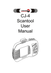
CJ-4
Scantool/Oscilloscope
User
Manual
CJ4 0000GEN/05A07/ENG
INDEX
INTRODUCTION
AA
GENERAL DESCRIPTION
1
CHARACTERISTICS
1
FUNCTIONS
1
SPECIFICATIONS
2
LOCATION OF MAIN FEATURES
3
CONTENTS
4
KEY PAD
5
VEHICLE COMPATIBILITY
5
CONECTING TO THE VEHICLE
6
CJ4 MAIN MENU OPTIONS
7
OBDII GENERIC
INTERFACE MODE
EXECUTE CARD
LABSCOPE
Instructions by section, below.
BATTERY TESTER
SCREENSHOTS
INFO CENTER
OBDII GENERIC
11
QUICK TEST
11
PERMANENT CODES
15
PENDING CODES
18
CLEAR CODES
19
FREEZE FRAME
20
READINESS STATUS
21
LIVE DATA MENU
23
SELECTING
24
LIVE DATA
28
GRAPH 1
30
GRAPH 2
32
O2 TEST
35
VIN
39
PROTOCOL INFO
40
DTC LIBRARY
41
CONFIGURATION
47
INTERFACE MODE
50
SERIAL (a)
50
USB (b)
51
WIRELESS BLUETOOTH (c)
52
Continued on next page
A1
INDEX (continued)
EXECUTE CARD
LABSCOPE
SPECIFICATIONS
CONNECTING THE TEST LEADS
MAIN MENU
SINGLE CHANNEL
VOLTAGE ADJUSTMENT
HOLD
CHANNEL
TIME
TRIGGER
WAVE FORMS
2 CHANNEL
VOLT METER
HOLD
RESET
CHANNEL
FREQUENCY GRAPH
SELECTING THE SCALE
SELECTING THE CHANNEL
ESPAÑOL/ENGLISH
BATTERY TESTER
The technology behind the Battery Tester
Innovations in battery systems
Integrated solutions
SAFETY AND CAUTIONS
CARE AND MAINTENANCE
INTRODUCTION
FUNCTIONS
BEFORE STARTING THE TEST
OPERATING INSTRUCTIONS
BATTERY TESTER MENU
TEST BATTERY
STARTER TEST
CHARGING TEST
CHANGE LANGUAGE
Continued on next page
A2
53
54
55
56
57
60
60
61
63
64
66
69
72
73
74
75
76
77
78
79
80
82
84
84
85
86
87
88
88
89
92
93
94
INDEX (continued)
SCREENSHOTS
EXTRACTING THE SCREENSHOTS
INFO CENTER
INFORMATION CENTER MENU
ACRONYMS
CONNECTOR FINDER
LANGUAGE
WARRANTY
95
98
104
105
105
109
111
114
A3
INTRODUCTION
New technologies implemented in automobiles and the necessity to diagnose this vehicles has encouraged Injectronic to take the
initiative of developing new equipment to satisfy this needs.
As the result of a series of marketing investigations, the search
for high quality and reliable components, as well as skilled manufacturing process from design, engineering and production, surges a final
product, the CJ4 Scantool/Oscilloscope automotive diagnostic equipment.
The CJ4 Scantool/Oscilloscope with its scanning capacity,
generic OBD II, EOBD and CAN plus the Labscope feature, is ready
for most vehicles in circulation on countries around the world. In addition, the expansion port accepts optional cartridges that allow the CJ4
Scantool/Oscilloscope to perform diagnostics in vehicle specific
mode and special functions like the optional Fuel Injector Tester. And
to complement this features, the CJ4 Scantool/Oscilloscope supports an optional Battery Tester to make a complete and thorough diagnostic.
Furthermore, the integration of the oscilloscope for testing all
electronic automobile systems and ease of operation, characteristic of
Injectoclean equipment, gives you added functionality.
As always, Injectronic appreciates your preference, and invites you to read this user manual carefully so that you can take full
benefit of your CJ4 Scantool/Oscilloscope.
AA
GENERAL DESCRIPTION.
Characteristics:
•
128 x 128 pixel resolution, illuminated screen, for better visibility outdoors.
Integrated 2 channel oscilloscope.
Optional cartridges for wider coverage and additional applications.
Graphs live data parameters.
No batteries required.
Updateable via Internet/PC.
•
•
•
•
•
Functions:
•
•
•
Retrieve permanent and pending trouble codes.
Code description of most vehicle-specific trouble codes.
Erase trouble codes from computer memory and turn off the MIL indicator (Check Engine).
Display Freeze Frame data, captured when a fault code is set.
Live data parameters displayed in digital format.
Graphs live data parameters.
Monitors Emission control system parameters.
Digital Voltmeter.
Oscilloscope with single or 2 channel option.
Double cursor on graphs.
Screen Shots.
Multi-language application.
Stand alone or PC/Laptop interface modes.
USB and Serial communications supported.
Compatible with our 4514 Battery tester.
•
•
•
•
•
•
•
•
•
•
•
•
1
SPECIFICATIONS.
•
SUPPORTED SYSTEMS:
OBD II.
CAN
ISO 9141
J1850 PWM
J1850 VPW
ISO 14230-4
SCI
CCD
18.7 cms. x 11.15 cms. x 5.60 cms aprox.
(7.40” x 4.40” x 2.20” approximate)
(CJ4 housing, no cables or module).
350 gms. (12.35 Oz.) Approximate
(CJ4 monitor, no cable).
128 X 128 Pixels.
•
PROTOCOLS:
•
DIMENSIONS:
•
WEIGHT:
•
•
SCREEN:
TROUBLE CODES SUPPORTED:
•
OSCILLOSCOPE:
•
•
LANGUAGES:
UNITS OF MEASURE:
•
EXPANSION PORT:
P, B, C, U.
2 Channel
500 Mhz samples
0 to 20 volts scale
English-Spanish, others optional.
English/Metric
•
MODULES:
•
POWER:
Yes
Optional, 2 to 16 MB memory with specific
and special applications.
Self-powered when connected to Data Link
Connector on vehicle.
2
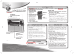
LOCATION OF MAIN FEATURES ON THE CJ-4.
A
B
D
C
E
Bottom view
F
Fig. 1
G
A) Memory cartridge for applications/specific functions (OPTONAL).
B) “Banana” type connectors for test leads used with the Oscilloscope function..
C) 128 x 128 Pixels screen, with integrated illumination.
D) DB15 connector, for OBD II cable assembly.
E) Membrane type Key pad with 6 pressure sensitive buttons.
F) USB type connector for PC/Laptop connectivity.
G) Serial type connector for PC/Laptop connectivity.
3
CONTENTS in storage case:
•
•
•
•
•
•
•
CJ-4 Scantool.
User Manual.
OBD II cable.
USB cable for PC connection.
Serial cable for PC connection.
High impact plastic storage case.
Oscilloscope cables (3) with alligator clips and test probes.
(*)
(*)NOTE: Memory cartridges with specific or special applications are
optional and are not included with the CJ4 package.
4
KEY PAD.
Key Functions
ESC (Escape):
Returns to previous step / screen.
ARROWS:
Allow; up, down, left or right movement and scrolling in menus.
ENTER:
Press after making a selection in a menu and to freeze readings.
VEHICLE COMPATIBILITY.
The CJ4 Scantool is capable of communication with Domestic, Asiatic
and European vehicles that conform to the OBD II standard.
CAN communication is included, introduced to the market in 2003 and
will be required on 100% of vehicles sold in the US starting in the year 2008.
5
The CJ4 integrates the EOBD diagnostic system used in Europe and
other countries since the year 2000.
CONNECTING THE CJ4
-FIRST plug in the matching end of the OBDII cable to the DB-15 connector in
the CJ4 (located in the upper side of the CJ4) See fig.#1 (D). Taking care to
guide the cable end straight into the CJ4 to prevent damage to the pins or
the receptacle. Tighten the screws evenly using finger force only.
-Locate the Diagnostic Link Connector (DLC) under the dash in the vehicle,
usually at the left or right of the steering wheel. Consult the vehicle owners
manual or service manual for exact location.
-Plug the OBDII end of the cable to the DLC.
-The CJ4 should be energized and display the “CJ4 MENU”, turn ignition key
to the ON position.
6
MAIN MENU OPTIONS.
Once the CJ4 has turned on, the screen will show the main
menu for the CJ4’s functions with the following options:
OBDII GENERIC:
Allows diagnostics on OBDII in generic mode, CAN protocol and EOBD systems.
INTERFACE MODE:
This function allows the CJ4 to enter into a communication interface mode
between the vehicle and a PC, Laptop or a PDA. Support for serial, USB and
wireless Bluetooth options.
EXECUTE CARD:
With this function the CJ4 Scantool increases its diagnostic power when
using special applications integrated into optional cartridges that are inserted
on the upper back side of the equipment.
LABSCOPE:
The incorporated oscilloscope option allows viewing in real time, wave forms
of positive values of electrical signals, necessary to analyze the impulses received and sent by control units, sensors and actuators of automotive electronic systems.
LANGUAGE:
Change the language, English / Spanish, of the CJ4 Menu, the OBD II Generic submenu and functions, also the Extras menu will be affected by the
change. Other menus and functions have their own option to change language. Refer to each submenu function for instructions.
7
BATTERY TESTER:
The CJ4 is ready to make use of the Injectoclean/Midtronics 4514 Battery
Tester. In just a few minutes you can obtain accurate analysis on battery condition, starting and charging systems, crucial for the operation of the vehicles
electronics.
SCREENSHOTS:
This option allows viewing of stored screenshots in the CJ4 Scantool.
This feature allows you to review, save and delete stored screenshots without
the need to use a PC. Use the CJ4 Screenshot Tool and Screenshot converter to transfer, save and customize screenshots in your PC.
INFO CENTER:
ACRONYMS:
In here you can look up the full description of most common acronyms used in
automotive diagnostics, components and systems. If more then one description applies, they will be displayed in the same window.
CONNECTOR FINDER:
OBD2 Diagnostic Link Connector (DLC) location of approximately 1600 models is accessible here, Select make, model and year then, text and a graphic
appear in the screen to guide you to the location.
LANGUAGE:
You can select the language for the acronyms and connector finder functions.
EXTRAS:
When updates become available for the CJ4, there may be added extras from
time to time. This extras may include a basic vehicle application or function
that complements the operation and functionality of the CJ4. Most, if not all of
this extras will be included in the update at no cost, FREE.
NOTE:
The CJ4 is capable of capturing screenshots from the following functions: OBDII Generic, Labscope, Battery Tester and from the Info Center’s
Acronyms and Connector Finder.
While on OBDII Generic, Battery Tester and Info Center functions,
press and hold the DOWN key for about 2 seconds to capture the screen.
For the Labscope function, press and hold the LEFT and RIGHT arrow keys at the same time for about 2 seconds to capture the screen.
Refer to the Screenshots section for instructions on the options available to manage the captured screenshots.
8
DIAGNOSTICS.
Once the CJ4 has been connected to the vehicle and the Main Menu
is visible, the “OBDII GENERIC” option will be highlighted, press “ENTER” to
access the Scantool functions of the CJ4.
In the next screen, you can see what firmware version is installed.
Press “ENTER” to continue.
NOTE: Regularly visit the
Injectronic website for
the latest firmware and
updates available.
9
After pressing “ENTER” the CJ4 will automatically detect the protocol
on that vehicle, once the correct protocol is found, communication will be established and the diagnostic will start.
The CJ4 has the capacity to retrieve data from the following protocols;
CAN, ISO 14230 Fast Init, ISO 9141, J1850 VPW, J1850 PWM.
The protocol detection is visible with the protocol name and search
bar representation. As the search progresses, the horizontal bar will “fill” and
once the correct protocol is found, the search stops and communication will
start.
If the CJ4 cannot detect a protocol, “Unknown Protocol” will appear in
the screen. Retry doing the following;
-Disconnect the DLC connector from the vehicle,
-Disconnect and reconnect the cable at the CJ4 connector,
-Reconnect to the vehicle DLC.
If there is still no detection of protocol, check for the following;
-Faulty DLC connector or damage to wiring in vehicle.
-Refer to service manual for other causes.
10
Once communication has been established, the menu for generic
diagnostics will be shown in the screen.
OBDII/CAN GENERIC MAIN MENU.
To navigate through the options, press the up or down arrow
keys then press “ENTER”.
-QUICK TEST.
The CJ4 integrates this test that permits a fuel injection system diagnostic in a matter of seconds. This type of diagnostic is convenient as part of
routine service, or as preventative maintenance with very low labor involved
and practically no cost.
The information provided by the CJ4 Scantool cover the primary data
needed to begin a diagnostic:
•
Monitors
•
Permanent fault codes
•
Pending fault codes
•
Freeze Frame data
11
Selecting the Quick Test option for OBDII/CAN Generic in your CJ4 is
the first function in the diagnostics menu. Since this option is already highlighted just press “ENTER” to start executing the automatic series of tests.
Press ENTER key to
start the test.
NOTE: Due to the quickness of the diagnostic, some of the screens won’t be
visible long enough to appreciate the information.
12
At the end of the diagnostic, a second window will open with either a;
Problem detected or No Problem test result.
The CJ4 Scantool considers a No Problem result if:
•
No Permanent codes
•
No Pending codes
•
No Freeze Frame data
•
Monitor Status is OK
This is an overall test of systems and
main components, to detect a problem or
display indication of saved data in
the vehicle’s computer.
In the result window there are 2 buttons, the “OK” button is highlighted automatically, pressing it will reveal the individual results of the tests:
Quick Test overall results
Results for Permanent
and Pending codes.
Availability of Freeze
Frame data is indicated here.
Each test section results are displayed here.
If problems are detected in any section, “Yes”
will appear for that test.
13
If the results of the Quick Test find a problem the Problem Detected
message will show on the secondary window:
Pressing the “ENTER” button will show the individual test results,
allowing you to view where the problem(s) was detected.
In this example, Permanent codes are detected
and Freeze Frame is available for review.
You can review the results for each of the tests. Each test is performed like if it was done manually, so pressing “ENTER” on any particular
block will display results for that test. For example: if you press “ENTER”
when the Permanent Codes block is highlighted, the number of codes and
their description will be displayed.
Press “ENTER” on any of the other blocks to display the results for each.
Permanent codes (page 14)
Pending codes (page 17)
Freeze Frame (page 19)
•
•
•
The bottom of the screen displays a Help message.
14
-Permanent DTC.
This function displays Permanent trouble codes (DTC) captured in the
vehicle’s computer.
The following screen will display DTCs and their description:
Code description.
Number of DTCs retrieved
System and code number.
If more than one code is retrieved from the computer, the top of the
screen will show the following information:
DTC sequence number on display from total codes retrieved.
15
This is the total number of
codes that are registered in
the vehicles ECU.
To be able to see all the codes retrieved, press the RIGHT arrow key
to display each one, in ascending sequence.
The left and right arrows indicate that it is possible to scroll
through all of the retrieved
codes.
Sequence position of the
code in display.
Total number of
retrieved codes.
To see each code one by one, press the RIGHT arrow key then the
next available code in the sequence is displayed. This is done in an ascending manner. Press the RIGHT arrow key once for each code.
Description of the code is displayed in each screen.
16
To review previous codes in the sequence simply press the LEFT
arrow key. Each time that you press it, the screen will show the code number
and description of the codes in descending sequence.
Pressing the RIGHT or LEFT arrow keys will not delete or retrieve
more codes.
Pressing
the
LEFT arrow key
returns to a
previous code
in a descending
manner.
If when the Quick Test was performed there were no codes stored in
the vehicle’s ECU, the following screen will be displayed:
The “OK” button will be selected by default, press the “ENTER” button
in the key pad to exit from this screen and return to the diagnostic menu.
17
-Pending DTC.
This option allows you retrieve any codes that are stored in the vehicle’s computer but have not set the MIL light on. An intermittent problem or an
operating malfunction may have been detected by the computer for a short
period of time but it did not re-occur again or if it did, it was not constant or
severe to trigger a Permanent code.
If a malfunction is constant or severe and the MIL light stays on, then
it becomes a Permanent code.
If more then one Pending code is registered, you can review the
codes in the same manner that for Permanent codes, by pressing the RIGHT
and LEFT arrow keys.
18
-Clear DTC.
The CJ4 can clear Permanent and Pending codes captured by the
vehicle computer. Also, the Check Engine light will be turned off. Normally this
is done after the cause of the trouble code(s) has been repaired.
In the Main menu, highlight the “Clear DTC” option and press the
“Enter” button in the keypad of the CJ4 and the following screen will appear:
By default the “OK” button is highlighted, pressing “ENTER” in the keypad will
erase all DTCs stored.
Note: When clearing codes from the vehicle memory, you erase freeze
frame data and the vehicles adaptive memory is cleared also.
If you are not sure that you want to loose this data, press the RIGHT arrow
key to highlight the “CANCEL” button and then the “Enter” key. Doing this will
take you back to the Diagnostic Main Menu.
Highlight the CANCEL button to
exit from this screen and abort
the clear DTC function.
19
-Freeze Frame.
The Freeze Frame function displays the operating conditions of the
vehicle at the moment that a fault code is triggered and the code is recorded.
The information available in the Freeze Frame screen depends on
what is available by the manufacturer, and it varies by vehicle make and
model.
General information includes; engine RPM, engine temperature, engine load, vehicle speed, fuel trim and systems status.
DTC registered at time the
fault code was triggered.
This are the
parameter values registered.
The available parameters from
the vehicle are displayed here.
20
-Readiness.
The Readiness Status function analyzes the emission control system,
this system is constantly supervised by the Engine Control Module, it’s purpose is to determine that all the emission components are functioning properly
and the monitoring cycle is complete.
Emission control monitors functioning depends on the test results
executed by the ECM. This can determine if the test was Complete, Incomplete or is Not supported.
Availability of monitors is dependent on the design of the fuel injection
system in the vehicle.
In the Diagnostic Main menu highlight “Readiness” and press “Enter”,
this screen will be displayed:
Monitor tested
Monitor condition
This arrow indicates that
there are more registered
monitors, to view them, press
the DOWN arrow key.
21
To see more available monitors in the vehicle, press the Down arrow
key and more monitors will appear
Monitor Name
Monitor’s condition
The arrows on top and
bottom of the scroll bar
indicate in which direction are more available
monitors. To move up or
down use the Up and
Down arrow buttons in
the key pad.
When you scroll up or down another monitor will be highlighted, when
you get to the bottom or top, only one arrow will show in the scroll bar.
In this example we have
reached the last monitor at
the bottom, notice that only
an arrow at the top of the
scroll bar is present. Press
the Up arrow key to return
to the top, while doing this,
an arrow at the bottom of
the bar will appear again.
You can return to the
diagnostics main menu
at any time by pressing
the “ESC” key in the CJ4.
22
-Live Data Menu.
Live Data allows visualization of all available parameters from the
engine control systems, such as: engine RPM, TPS, charge percentage, etc.
All parameters are displayed in digital format.
To access this function, press the Enter key when you are in the diagnostic main menu. The following menu will appear on the screen:
The following options are available in this function:
•
•
•
•
23
Select Parameters
Live Data
1 Graph Live Data
2 Graph Live Data
-Select Parameters.
This option permits you to select the parameters that are most important to you or for the diagnostic being performed. The amount of parameters
depend on the total available from the vehicle. This reduces the time needed
for the diagnostic by having less parameters to search through.
The default option on the Live Data menu is Select Parameters, press
the Enter key on the pad and the following screen will appear.
As an example, you only want the following parameters:
•
•
•
•
•
LOAD_PCT
MAP sensor
Engine RPM
MAF sensor
O2S11 (Oxygen sensor 1 Bank 1)
The next steps will guide you through the process;
24
To select the first parameter, LOAD_PCT, use the Down arrow key to
highlight that block, then
Press the Right arrow
key to add to the list
A Check mark will appear in the box.
This arrow indicates that there are
more parameters available.
Press the Down arrow to see them.
The next parameter to select is the MAP,
press the Down arrow until it is visible.
25
Once the block has been highlighted, press “Enter” to add to the list
then press the Right arrow key to put a Check mark.
1– Highlight parameter
2– Press Enter to select
3– Press Right arrow to
put Check mark.
Repeat same steps for every parameter that you want to include in
the list.
26
If you made a mistake or don’t want a parameter after all, scroll with
the arrow keys to the desired parameter and press the LEFT arrow key, the
check mark will be taken off and that parameter will not be in the list.
To delete a parameter from
the Live Data list,
1– Highlight the parameter,
2– Press the LEFT arrow key,
3– The check mark is cleared.
Once you have selected the parameters that will be shown on the list,
press ESC in the keypad. The screen will go back to the Live Data display
then, press the Down arrow key to highlight “Live Data” and press ENTER key
to start viewing the selected parameters.
27
-Live Data.
With Live Data you can view values and engine operating conditions
and systems that provide data under the generic standard.
The CJ4 has the capacity to interpret up to 104 live data values. The
values displayed are dependent on the vehicle, in other words, the amount
and availability of such information varies by manufacturer and vehicle model.
All available parameters displayed are viewed in real time.
The CJ4 screen displays the parameter name, value and a simultaneous graph of the parameter that is highlighted.
To view a particular parameter value in a graph, press the Down arrow key then press ENTER and that parameter’s graph will display at the bottom of the screen.
Highlight Live Data and press ENTER
Press Up or Down arrow keys to
select parameters.
Scroll bar moves accordingly.
Arrows at top and bottom of scroll
bar indicate more available parameters.
Parameter value displayed in a graph.
Each parameter has a predetermined value range.
28
Every time that you press the Down arrow key the parameter underneath will
be highlighted and its value displayed in a graph.
Arrows indicate more parameters available at top or bottom
of the list.
The new parameter selected
displays it value and the graph
changes as well, in real time.
Here we see an arrow only at the
top, indicating that there are no more
parameters available at the bottom.
The range value changes
with every parameter, the
value adjusts to the most
common for that parameter
under normal conditions.
29
NOTE: The screens shown in here are for illustration only, the CJ4 can retrieve up to 104 parameters, depending on the vehicle.
1 Graph Live data
The third choice in the Live Data menu, displays a single graph of a
selected parameter, from the ones available on the vehicle.
To start this function, select “1 Graph Live Data” by pressing the
Down arrow key to highlight it, then press “ENTER” key.
A single graph screen is displayed, in it on the upper left corner, you
will see a drop down menu window in which you can select a parameter to
view.
When you enter this screen,
a graph of the
parameter in
the drop down
window will
start appearing.
To change the
parameter, press
the Down arrow
key on the CJ4 to
reveal the available parameters.
30
All available parameters will be shown in the drop down window.
Using the Up and Down keys, search for the parameter that you want to be
graphed by the CJ4.
Press the Down arrow key to
unfold the drop down menu.
Once you have selected
another parameter press
ENTER to start graphing
the selection.
The CJ4 will start displaying the new parameter selected.
Selected
Parameter
Minimum and
Maximum values, according
to each parameter
Numerical value
of the parameter,
in real time.
The graph
reflects the
numeric value as
it updates at the
same time.
Repeat the previous steps to select another parameter to be graphed.
31
2 Graph Live Data.
This option allows the technician the ability to view 2 different parameter graphs simultaneously on the screen in real time. This function is very
useful, especially when verifying two different signals that are linked to a system.
To access this function, from the Live Data menu, highlight “2 Graph
Live Data” and press the ENTER key on the CJ4 pad.
The following screen is displayed in the CJ4.
An example of this functions is this; we need to verify operation of a
TPS at the same time with the engine RPM.
We need to select each parameter in the upper and lower graph sections of the screen.
32
First press the Right arrow key, the drop down menu of the upper
graph is unfolded to show the available parameters.
Next, with the UP and Down
arrow key scroll to the desired
parameter, when it is highlighted, press the ENTER key.
In this case it will be RPM.
The RPM signal will generate its
numeric value and graph will be
displayed automatically in the upper section of the screen.
To select the second parameter, press the Right arrow key, then the
lower drop down menu window gets “framed”, then press the Down arrow key
to unfold the window’s drop down and the available parameters are shown.
33
Repeat the same steps like for the selection of the first parameter,
remember it is done by pressing the Up and Down arrow keys then, the ENTER key.
1– Use Up and Down arrow
keys to select parameter.
In our example, the TPS.
2– Press the ENTER key.
When this operation is completed, the following screen will be displayed:
The parameter values and
graphs get updated at the
same time.
The graph’s leading edge
(live data) is all the way to
the right.
If you select a parameter by error or you want to see another, press
the Right arrow key to switch between the upper and lower drop down windows, then press the Down key to unfold the menu, select the parameter and
press ENTER key.
The graphs will continue to get generated as the signal is retrieved by
the CJ4, this is done indefinitely.
To exit this function press the ESC key to return to the Live Data
menu.
34
-O2 Tests.
The Oxygen sensors provide information to the computer as to the
amount of Oxygen in the exhaust gases exiting out the tail pipe. This information helps the engine computer in determining fuel injection delivery amount to
try and reach the ideal Stoichiometric ratio. This ratio is the mixture of air and
fuel equivalent to 14.7:1. 14.7 parts of air to 1 of fuel, this “ideal” mixture burns
efficiently without contamination. This proportion is also known as Lambda.
There are many factors that prevent to always reach this mixture on
gasoline internal combustion engines, some are; engine temperature, intake
air temperature, altitude were the vehicle is operated, etc. The result is, generating contaminating levels that can be high.
Because of this, ecological deteriorations occur, governments in
many countries promote laws that require automobile manufacturers to implement systems that reduce this type of emissions. Another factor that prompted
de development of emission controls, was the fuel crisis of the 1970s, that
mainly affected the USA, generating since then, strict regulations for emissions outstanding, the state of California.
Encompassed in the progress of the On Board Diagnostics (OBD I
and OBD II), more tests have been added to this systems, that allow monitoring the function of the Oxygen sensors.
The CJ4 includes the Oxygen sensors test, which allows verification
of response time, operating voltage range for each sensor in its respective
bank.
35
It is important to clarify that the availability of sensors, how many and
what kind of testing, is in accordance to manufacturer specifications, considering also the variations that each make, year and vehicle model.
From the OBDII/CAN Generic main screen, use the arrow keys to
highlight the “O2 Tests” title and press ENTER key.
On this screen press ENTER,
the CJ4 will look in the vehicle
computer for available sensors.
A new screen “Oxygen
Banks” will show the available
O2 sensors and their position.
Press ENTER key to start the
test on this O2 sensor, or select another by pressing the
Up or Down keys then press
ENTER.
NOTE: In order to adequately perform this tests, the engine needs to
be idling and coolant temperature at normal range. Otherwise the tests will be
erroneous and display wrong data.
36
For this example we are going to test “Bank 1 Sensor 1”, the following
screen will be displayed with the results of the test.
Description of
and position.
sensor
Description of test performed
to this sensor.
Minimum range of
the test.
Value
registered
during the execu-
Test result for this
sensor.
Maximum range
of the test.
Position of the test
performed,
arranged in consecutive order.
Total of tests performed on this
sensor.
To see the rest of the test results, just press the Right arrow key, the new
screen will show the results for the next test in the sequence of tests performed to this sensor.
Press
t h e
RIGHT
arrow
k e y
again
for next
results.
Notice that the test result sequence number changes on each new screen.
37
Once you have reviewed all the results for Bank 1 Sensor 1, press the
ESC key to return to the “Oxygen Banks” screen in which you can select another sensor for testing, Bank 1 Sensor 2 as in our example.
Press the ENTER key to initiate the tests by the CJ4.
Again, the test result screen will display Oxygen sensor data, now for
Sensor 2 on Bank 1. If more then one test was performed on this sensor, all
results are available by pressing the Right key.
Number of tests performed
on this sensor.
Remember that the CJ4 only tests those sensors that are available for
test in the vehicle. The CJ4 may detect the sensors but it wont be allowed to
perform the series of tests, this function is vehicle dependent.
38
-VIN
The VIN or Vehicle Identification Number is a series of 17 digits, usually numbers and letters, assigned at the factory and is unique to each vehicle. This number contains information such as make, year and model, engine
size, and factory serial number for that particular vehicle.
This feature is available on those vehicles that, from factory according
to make, year and model, is recorded into the ECU.
With the UP and DOWN
arrow keys highlight “VIN”
and press ENTER
If this information is available from
this vehicle, this screen will appear.
If the vehicle does not
support this feature this
screen will be displayed.
39
-Protocol info.
This function will display the characteristics of the communication protocol that the vehicle being tested has.
•
Protocol:
Is the communication standard for that vehicle.
•
Baud Rate:
Is the signal communication speed between the vehicle’s
computer and the CJ4.
It is measured in Kbps = One Thousand Bauds per second.
•
OBD II Pins:
The numbers displayed indicate the pins that are used by the
DLC connector to transmit data between the vehicle’s
computer and the CJ4 Scantool.
40
-DTC Library.
One of the characteristics of the OBD II system is that codes and their
descriptions tend to be standardized. Trouble Code or Fault Code are the
common names used to describe that the vehicle’s computer has detected a
problem. In previous OBD systems, codes would be 1, 2 or 3 digits, and were
represented by numbers only.
The J2012 standard, establishes definitions for trouble codes that
affect systems related to emissions. The codes used by OBD II systems are
five digits long, start with a letter, and followed by 4 numbers. Since they start
with a letter, the only way to retrieve and understand them is with a scanner
like the CJ4 Scantool. The range of codes was designed to allow for expansion in the future.
Universal Designation.
The first number next to the letter indicates if the code is common for
all auto makers (P0xxx). This code is used by most manufacturers, the number and description is similar. This codes are widely known as Generic.
The letter identifies the system which registered a problem.
P
B
C
U
Engine and Transmission
Body
Chassis
Vehicle Systems Communication Network
Specific Designation.
Each auto manufacturer has particular conditions in the design of
their systems. This codes are not used by all manufactures, due to their basic
system of operation, diagnostics procedures or variations in their implementation. This codes are known as Specific (P1xxx).
Specific codes P1xxx are designated with their own description and
assigned for a specific fault or system. Even though codes are assigned by a
manufacturer for the same make, they have variations in their use on different
models and years.
41
DTC Numbering system.
The second digit (from left to right) in the code number, indicates a
system or subgroup were the fault was detected. This number is consistent in
generic P0xxx and specific P1xxx codes. The standard is like this:
P0100
Air intake and fuel systems.
P0200
Fuel system, related to fuel injectors only.
P0300
Ignition (Misfire).
P0400
Emission Controls.
P0500
Idle Speed Control or Vehicle Speed Sensors.
P0600
Actuator Components (Relays, Solenoids, etc.)
P0700
Transmission
This function can be used without having to retrieve codes from the
vehicle, if you know or want to find out any generic code description.
The CJ4 has an integrated library, which you can consult for generic
code descriptions generated by most OBD II vehicles.
To access this feature, from the OBDII/CAN Generic menu, press the
Down arrow key until the DTC LIBRARY title is highlighted then press ENTER.
This screen will be displayed in the CJ4.
42
For example, we are going to search for description of code P0837.
When this screen is accessed, the first window is “framed”, in there
we are going to select the letter for the system that the code is from.
Press the Down arrow key, the drop down menu will show the predetermined choices, P, B, C, U.
Using the Down arrow key select
the letter “P” for the code that we
are looking for, then press ENTER. The menu will close and the
letter will show in the window.
Next, press the Right arrow key to move to the second window. This window
will be “framed” and ready to be accessed. Press the Down arrow key for the
drop down menu to appear.
43
The numbers 0
to 5 will appear
first, if the number that you are
looking for is
here, press the
Down key to
highlight it.
Keep pressing
Down key to go
to numbers 6 to
9. Stop at the
desired
number. In our example is 0, so
we need to
press the UP
key to reach
the number 0,
once
there,
press ENTER.
NOTE: The library in the CJ4 is for generic descriptions only, so the
second digit should be 0.
Now it’s time to select the third digit (8) in our code description
search.
Press the Right arrow key to “frame” the next window. Once there, press the
Down key and again, the numbers will appear in the drop down menu.
Repeat the same process as we did for the second digit to
select the number 8 for our code. Repeat the steps for the
fourth and fifth digits.
44
Select number 3
Select number 7
Notice that description
for the code that
matches the numbers
in the boxes is displayed, continue to
the next box to make
selection of next number.
RECAP:
1– “Frame” a window.
2– Press Down arrow key.
3– Press Down or UP keys to highlight a number.
4– Press ENTER to select number.
5– Press Right arrow key to “frame” next window,
and repeat steps 2-5 for next digit.
45
As mentioned before, every time a digit is selected, description for the
digits in the boxes is displayed.
We have made our last digit selection and automatically the description to the P0837 code is displayed as seen in the screenshot below.
The number in the
code description
window is the
same as the one
you entered
Full description is displayed in the window.
If you entered a code number that is manufacturer specific, there may
be no description available, the same is true if you entered a bogus number.
In the future, memory cartridges with specific vehicles applications will
be available and code descriptions for the same will be accessible in the
same manner.
46
-Configuration.
The CJ4 Scantool has the capacity to display information in English or
Spanish. Also, you can change the units of measure between English and
Metric. When the CJ4 is switched to Spanish, not only the functions are displayed in Spanish but also the code descriptions. Refer to page 7 “CJ4 Main
Menu” and the “Language” submenu for instructions on how make changes.
This configuration option applies to the OBDII/CAN Generic submenu
and is for the parameters units of measure.
To change units of measure, follow this procedure.
Use the Down arrow key to highlight the “Configuration” title then
press ENTER in the keypad of the CJ4.
Press ENTER key
when Configuration is highlighted.
The next screen will appear, then
press ENTER.
47
The screen displays the Metric and English units of measure options.
With the UP and DOWN arrow keys make your selection
and press ENTER.
After your selection and having pressed ENTER, the screen will display the
units of measure that will be represented when viewing parameters.
It is recommended to set the CJ4 accordingly to the type of vehicle being
worked on. If you are working on a vehicle made in or for the USA the best
setting is English System units of measure, since most specifications in service manuals are in SAE.
For Asiatic and European vehicles, the recommendation is Metric system, since this is the standard for DIN and JIS.
48
Screenshots reminder.
The CJ4 has the ability to take screen shots of the information being
displayed on the screen, in practically all of the functions.
Screen shots are very easy to take;
•
When you are working in either the OBDII GENERIC or Battery
Tester functions, just press the Down key for 2 seconds, on any
diagnostic screen then, a window will appear with the message:
“Screen Shot ready”.
•
To take a screen shot when in the Labscope option, you need
to press the LEFT and RIGHT arrows key at the same time, the
“Screen Shot ready” message window will appear on the
screen.
The screen shots will be stored in the memory of the CJ4 Scantool in
a progressive manner, the CJ4 will assign a number that is consecutive, without regards to which function (OBDII Generic, Battery Tester or Labscope)
they were taken from.
To manage the images stored in the CJ4 consult the section “Screen
shots” in this manual.
49
INTERFACE MODE (a)
With this option, the CJ4 can communicate via a serial cable, USB or
wireless Bluetooth with PC/Laptops and PDAs.
This communication option allows the CJ4 with the ability to act as a
data communication interface between a vehicle and a PC, and to take advantage of the diagnostic programs developed by Injectronic, which permit
preparing a report and option to print with the shop and customer information.
Another function of this type of connection is for updating the CJ4,
and to transfer data like screenshots to a PC.
SERIAL:
To set the CJ4 to the serial Interface Mode, press the Up or Down
arrow keys in the key pad to highlight the “Interface Mode” option in the Main
Menu of the CJ4.
Connect the serial
cable to the CJ4 and
COM port in PC.
This end to the
RJ45 port in the
CJ4. (see figure
1-G on page 3)
Now press ENTER
and this image appears in the screen
This end to a
COM port in a
Laptop or PC.
Next, open an Injectronic
program in the PC and
select the COM port assigned to the CJ4 to establish the connection.
Follow instructions for
each particular program.
50
INTERFACE MODE (b)
Additionally to the serial communication port, the CJ4Scantool can be
connected to a PC or Laptop with the USB cable (supplied), this feature allows the CJ4 to be used with any newer computer that does not have a COM
port.
USB:
Follow these steps to set communication with the USB cable.
Connect the USB
cable to the CJ4 and
USB port in PC.
This end to a USB
port in Laptop/PC
Now press ENTER
and this image appears in the screen
This end to the
USB connector in
the CJ4. (See Fig.
1-F in page 3)
Next, open an Injectronic
program in the PC and
select USB in the RS232/
USB option window.
Follow instructions for
each particular program.
At this time you are ready to do either of this:
•
Use the CJ4 as an interface between a vehicle and a PC,
•
Transfer screen shots from the CJ4 to a PC,
51
INTERFACE MODE (c)
To make the CJ4 even more versatile, it can transmit data to a PC/
Laptop and PDAs via wireless Bluetooth © communication. An adaptor is an
available option accessory from Injectronic that permits this function.
Wireless BLUETOOTH:
The wireless Bluetooth adaptor comes complete with a connector
cable and the Bluetooth transmitter. Follow this instruction for this set-up.
Connect the adapter
cable to the CJ4.
This end to the
RJ45 port in the
CJ4. (See Fig.
1-G in page 3)
Now press ENTER
and this image appears in the screen
Next, open an Injectronic
program in the PC and
select the virtual COM
port for this connection or
the one assigned to the
adapter to establish the
connection.
Follow instructions for
each particular program.
To use this feature, your PC/Laptop needs to
be Bluetooth © enabled, an optional adapter
is available from Injectronic that allows this
type of communication.
(Not to be confused with WiFi)
52
EXECUTE CARD
This option allows the CJ4 to execute functions included in the external modules (cartridges) that are inserted in the back side of the CJ4. See
figure 1-A in this manual.
Insert the cartridge into the CJ4, making sure that it is securely in
place. Then, connect the OBDII connector to the DLC in the vehicle following
the procedure described in the “Connecting to the Vehicle” section of this
manual.
Once the CJ4 is powered on, select the “Execute Card” title on the
CJ4 Menu screen, using the Up and Down key to achieve this.
With the Execute Card title highlighted, press the ENTER key.
Depending on the application on the cartridge, the screen that is displayed next will be different, follow instructions included with the cartridge.
If no cartridge is inserted in the memory slot of the CJ4, this message
will appear on the screen.
Just press the ENTER key to return to the Main Menu of the CJ4.
53
LABSCOPE
“Seeing” the signals that sensors, actuators and communication between Control Units has become a necessity in recent model vehicles. This is
due to the increasing use more systems controlled by computers and those
computers take in signals from sensors and put out signals to actuators.
The CJ4 with it’s built-in Oscilloscope allows viewing those signals as
they go in and out of control modules. Decisions on the control modules are
made accordingly and affect the overall operation of the engine or system that
a particular signal, being input or output, is faulty or non-existent.
A quick explanation of an oscilloscope is this.
The signal picked up by the test leads is represented by lines in the screen
and this lines are a direct representation of the voltage that passes through
wires or goes in/out of sensors and actuators.
This voltage appears in a scale with two axis. Axis “Y” is vertical (updown) and displays the voltage available, axis “X” is horizontal (left-right) and
displays the length of time that voltage is present.
“Y” Axis
“X” Axis
54
SPECIFICATIONS
•
•
•
•
•
•
DC, 20 Khz
Max of 200 samples per second
1 Mega ohm, 25 pF input impedance
0 V to 20 V
Time scale from 312.5uS to 10 minutes
25mA power consumption at max sample rate
20uA I low consumption mode
NOTE: This Oscilloscope is for Automotive use Exclusively.
55
CONNECTING THE TEST LEADS
The CJ4’s Oscilloscope uses three leads to perform test;
•
•
•
BLACK, is a ground connection (negative), connect it first.
RED, is for channel #1 (positive)
YELLOW, is for channel #2 (positive)
- The OBD II connector has to be plugged in to power the Labscope.
- Both channels use the same connection to ground, the BLACK lead,
make sure you have a good clean contact (no paint or rust), best
when connected to battery negative post, engine block or ground point
- The CJ4 has female color coded connectors at the top to correspond
to the colors of the test leads.
- 3 “acupuncture” pin probes are included, they are used to pierce into
a wire or to “back-probe” on a connector. Caution should be taken
when handling the pin probes to prevent personal injury.
- When using the Voltmeter function or the Oscilloscope in 1 channel,
use the BLACK and RED test leads only.
RED
BLACK
YELLOW
Ground point connection
Red Pin Probe
Block Ground
56
Oscilloscope Operation
Plug the CJ4’s OBD II cable onto the ALDL connector in the vehicle,
highlight LABSCOPE in the CJ4 Main menu and press ENTER.
Oscilloscope Menu options
Single Channel will display only one graph,
of either, channel 1 or 2.
Use this setting to measure Voltage from
injector circuits, inductive sensors, Hall effect
sensors, O2 sensors and others.
Double Channel allows viewing two graphs
simultaneously.
This allows to get readings of input and output of a sensor, an actuator and a sensor,
battery voltage and a circuit voltage, etc.
57
Oscilloscope Menu options continued
The Voltmeter function is for simple voltage
readings. It is displayed in digital format only,
no graphs.
Frequency Graph refers to how many times
a signal is present. Sensors an actuators
work in this mode, some send and receive a
“square” or “wave” signal. (i.e. ABS sensors,
crankshaft/cam sensors, VSS sensor)
Here you can change the Language of all
functions in the Oscilloscope feature.
Reminder:
The screen capture feature is available in all the Labscope functions.
Please refer to the Screenshot section for instructions.
58
Access and Display features
Press ENTER when Single Channel is highlighted in the CJ4 main menu.
The following screen is displayed:
Maximum (high)
voltage range
displayed.
Selected Channel
on display.
Time scale selected.
Hold button allows
“freezing” the graph.
Minimum (low)
voltage range
displayed.
Channel select button.
Time scale select
button.
Voltage selector
button
Maximum voltage
registered during test.
In order to get an accurate reading, it is necessary to adjust the settings in the Labscope for the signal being tested.
In the next pages we are going to describe how to adjust (calibrate)
the Labscope, as well as the different functions available from the Labscope.
59
SINGLE CHANNEL
Voltage adjustment.
This adjustment is done by modifying the value on the button at the
bottom left corner in the CJ4 screen. This button is selected (highlighted)
when you first access the Single Channel function.
Press ENTER to display
the drop-down menu.
Press de UP or DOWN arrow keys to select the appropriate voltage
for the test about to be performed. The available voltage ranges are: 1, 5, 10,
and 20 volts.
Refer to a repair manual for the voltage value of the item tested, for
example: an oxygen sensor generates a signal of 1 volt maximum, inductive
type sensors 12 volts, etc. In order to get the correct voltage displayed during
the test, the voltage range needs to be adjusted.
60
Hold
The second button on the Single Channel screen is the HOLD button.
This feature “freezes” the display during a test, to analyze the wave form.
The Hold screen counts with two cursors, that can be moved to compare or view a value at any point in the wave form.
As an example, in the following screens we are going to explain each
item that is displayed.
The voltage setting is
displayed here.
Time scale setting on
this test.
This cursor is a solid
line and is on the
lead side of the
graph.
This cursor is a broken line and is on
the trailing side of
the graph.
=10.07Hz
This is the value of
the time between the
two cursors.
61
This is the frequency
value between the
two cursors.
When you press the ENTER key and the Hold button is highlighted,
the screen that is being displayed “freezes” and the following screen appears,
the cursors are positioned in a predetermined position in the graph, you can
mode them to any position within the graph.
This is the point were
This is the point were
the broken cursor
the solid cursor
crosses the voltage
crosses the voltage
line on the trailing
line on the leading
side of the graph.
side of the graph.
This is the value of
where the broken
cursor is in the graph.
This is the value of
where the solid cursor is in the graph.
To move the cursors, first, press either UP or DOWN arrow keys and
the value for the corresponding cursor will toggle accordingly (left or right cursor) then, second, press either LEFT or RIGHT arrow keys to move the selected cursor to the left or right of the graph. While doing this, the value of the
cursor will change as it is moved.
Selected cursor is indicated by arrow when
Up / Down keys are
pressed to toggle between cursors.
The Value is indicated
on highlighted window
when Left / Right keys
are pressed to move
selected cursor.
62
Channel
This option allows the CJ4 to display your choice of channel,
channel 1 is automatically selected when you access this function.
To change channel, first, using the RIGHT arrow key scroll to the CH1
button, then press ENTER, with the DOWN arrow key highlight CH2 and
press ENTER. Now the number 2 appears at the top of the screen in the middle, verifying that you are in channel 2.
Remember to have the Yellow test lead connected to a test source in
order to get a signal when in channel 2.
Repeat the same steps to return / change channels.
63
Time Scale
The time scale in use is displayed in the upper right corner of the
screen. This value is represented in the X axis (horizontal) of the graph.
To modify the time scale, with the RIGHT arrow key scroll to the time
scale button and press ENTER. A series of time options is displayed and they
range from 312.5 microseconds to 10 minutes.
With the UP and DOWN arrow keys, scroll to the desired time and
press ENTER key, the screen will show the scale in use now and the graph
will be adjusted accordingly. If no graph is visible, repeat the steps to select a
faster time scale until the graph is visible and you are able to make a diagnosis with the information being displayed.
Press RIGHT key 3 times
Min = Minutes
s = Seconds
ms = Milliseconds or Thousandths of a second
us = Microseconds or Millionths of a second
64
This adjustment is dependent on how fast the signal is generated.
It is possible to adjust the time scale to see different perspectives of the electrical signal, for example;
This is graph of a fuel injector in a V6
engine.
The time scale is adjusted to 100 ms.
The same injector with the time scale
adjusted at 50 ms.
In here we are looking at half of the
time then the previous graph.
In other words, we are zooming-in to
just about one cycle of the signal.
Still with the same injector and the
time scale adjusted to 500 ms (half of
a second), the graph shows more cycles (pulses).
Notice the details are not as visible as
with lower time scale settings.
65
Trigger
The trigger is used to stabilize and optimize the graph being displayed
There are three parts to configure the trigger.
Two modes:
1. Normal: The graph is refreshed if the signal meets the requirements set by other trigger configurations. Use this mode when a user identified signal is being tested.
2. Automatic: The screen is refreshed even if the requirements of
other configuration adjustments are not met. This mode helps to display
graphs like analog voltage.
And voltage level:
3. Level: This is a voltage value. In order to refresh the signal that is
displayed in the graph, it needs to reach the voltage level in Normal mode.
To adjust the trigger, press the RIGHT arrow key once the time scale
has been adjusted (see previous section), press ENTER again to display the
trigger options (Auto - Normal), using the UP and DOWN arrow keys make
your selection and press ENTER. While in Normal mode, the word NORM will
appear at the top right corner, bellow the time scale value.
66
Level
Once the trigger has been selected, the next adjustment is the trigger
voltage level.
Press the RIGHT arrow key when in the trigger mode screen, this
highlights the Level button, press ENTER. The indicator will move in the graph
to the trigger point and the value will be displayed at the bottom. The indicator
can be moved up or down with the UP and DOWN arrow keys, and its value
will change accordingly.
Trigger
Indicator
Move the trigger indicator with the
UP and Down arrow keys. Its value
changes in here.
67
Cursor
With this option you can make active the cursors in the graph with the
time and the frequency between them. This option is different then the one in
the HOLD feature (see page 61) which “freezes” the display, here the cursors
are used in real time to see the values of each cursor.
You can disable this feature and return to its initial state also.
Press the RIGHT arrow key to highlight the Cursor button and press
ENTER, the word Cursor changes to Settings. Now with the UP/DOWN and
LEFT/RIGHT arrow keys, move the position of each cursor and display the
value of each at the bottom of the screen.
Move the lines
(cursors) with the
UP/DOWN for cursor
selection and LEFT/
RIGHT for cursor
position.
Press ESC key
to return to the
starting cursor
positions.
68
Wave Forms
A selection of electrical wave forms of the most common automotive
sensors and actuators is available in this function of the CJ4.
The main purpose of this feature is to give the user of the Labscope a
reference of the ideal wave form for each of the elements in this list.
To access this information, press the RIGHT arrow key while still in
the Cursor settings from the previous section, the Waveform Library screen
appears. Press ENTER to display the list of available sensors and actuators.
Using the UP and DOWN arrow keys, scroll to the item that you want and
press ENTER, the wave form for that sensor or actuator will be displayed.
This is a list of the wave form graphics available in the CJ4:
•
•
•
•
•
•
•
•
•
•
•
•
•
•
•
•
•
•
•
69
ABS
CAM sensor
Crank sensor
EGR valve
Evaporative control valve
IAC valve
Ignition Coil
Injector
Knock sensor
MAF
MAF/MAP
RPM
Air Temperature
Engine Temperature
TPS sensor
Air Volume
VSS Hall type
VSS Optical type
VSS sensor
70
To return to the live graph,
press ESC twice and the
screen will look like this.
From here you have three choices;
1. return to select another sample wave form,
2. return to the live graph with the adjustments already done or
3. return all the way to the single channel settings screen.
71
DOUBLE CHANNEL
This function allows the CJ4 Oscilloscope to display two graphic wave
forms at the same time, with the same advantages of the single channel mode
Before starting with this application, is recommended that the test
leads are connected into the CJ4 and the BLACK lead to a good ground as
described in page 56 then the Red and Yellow leads to the components that
you are testing. The RED lead is for channel 1, while the YELLOW lead is for
channel 2.
In this example screen,
we have a fuel injector
and an
ignition coil signal.
All of the adjustments are the same as for the single channel display.
Note: The option to display wave forms is not available in the double
channel setting due to screen viewing area limitations.
72
VOLTMETER
Another function that is included in the CJ4’s Oscilloscope feature is a
Voltmeter. Useful to measure voltage to automotive electrical circuits.
Highlight Voltmeter in the Oscilloscope menu and press ENTER.
The Labscope takes voltmeter readings from channel 1 by default,
although, you can use channel 2 just by switching to channel 2.
Remember to always connect the BLACK lead first to the negative
side of the circuit or component being tested, then, the RED to the positive
side. If channel 2 is going to be used, either, instead of channel 1 or to another source, connect the YELLLOW lead also (remember to switch between
channels).
This is the Voltage
value of the component or circuit, it
refreshes every 30
milliseconds.
Minimum and
Maximum values
registered during
test.
Hold or “Freeze”
button.
Resets the Minimum and
Maximum voltage values registered during the test.
73
To switch between
channels 1 and 2.
Hold
The Hold function “freezes” the data on the voltmeter screen. Since
the Hold button is already highlighted when the voltmeter is accessed, just
press ENTER.
To continue, press ENTER again.
Press to
“freeze”.
Press to
continue.
Reset
This button resets the Minimum and Maximum voltage values registered during the test. Since the screen refreshes every 30 milliseconds the
reset to zeros is almost unnoticed.
An option that permits to actually see that the values have been reset
is to freeze the screen and then reset the value, this is done by pressing the
LEFT arrow key to highlight the Hold button and then press ENTER. Then
press the RIGHT arrow key to highlight the Reset button again and press ENTER, the values will become 0.00s (zeros). Now press the LEFT arrow key to
return to the Hold button and press ENTER, this “unfreezes” the screen and
returns to displaying live data, notice the Minimum and Maximum values have
changed and will continue to change every time the values go below the Minimum and above the Maximum.
The following graphics illustrate the procedure.
74
Min-Max values Reset feature
75
Channel
In the same way that in the Labscope Single Channel function, the
Voltmeter can be set to display data from either channel, each individually.
Once the Voltmeter function is accessed, connect the test leads to a
source; BLACK to ground, RED to positive for channel 1 and/or YELLOW to
positive for channel 2.
76
FREQUENCY GRAPH
With this option, the CJ4 Labscope can display a real time graph of
electrical signals, in a choice of two scales, from either of the two selectable
channels.
This type of display is useful for sensors that generate a “square” signal or sine wave.
First, connect the test leads, BLACK to a physical ground (-). Then,
the RED (channel #1) or/and the YELLOW (channel #2) to the sensor(s).
With the UP or DOWN arrow keys select Freq. graph and press ENTER.
Here is a description of the screen that appears:
The default scale
is .5 to 10 kHz.
Change the scale with this
button. Available scales are:
.5-10 kHz and 10-200.0 kHz.
77
Change the
channel to be
displayed in the
screen with this
button.
Modifying the scale.
There are sensors that generate a faster signal then others or have a
variable frequency like speed changes (RPM).
This is why the two scale options are offered, the default of .5-10 kHz
and an alternate of 10-200.0 kHz.
To make this change press ENTER when the Scale button is highlighted. Then the two available scales will be displayed, use the UP or DOWN
arrow keys to make the change and press ENTER. The screen will display the
change.
In this screen the graph looks different due to the change in frequency
(speed), making the graph more clear. To return to the previous setting,
repeat the same steps.
78
Changing channel.
If you are analyzing two separate signals, you can switch between
channels just by making this change in the following way.
Press the RIGHT arrow key to highlight the CH1 window, then press
ENTER. The CH1 and CH2 submenu will be displayed, use the UP or DOWN
arrow keys to make your selection and press ENTER.
Remember two things:
-1, the BLACK test lead needs to be connected to a good ground and,
-2, in order to make sure that you are looking at the correct component on
each channel, the RED test lead needs to be inserted into the RED connector
in the CJ4, as well as the YELLOW into the YELLOW in the CJ4.
It is not necessary to have the YELLOW test lead connected into the CJ4 if it
is not going to be used.
79
Español.
The CJ4 is bilingual and this feature is also available in the Oscilloscope function of the Scantool.
To change language just press ENTER when you have highlighted
Español in the Oscilloscope Menu. The screen will change automatically to all
Spanish language; Oscilloscope Menu, Submenus and functions.
80
Screenshots reminder.
The CJ4 has the ability to take screen shots of the information being
displayed on the screen, in practically all of the functions.
Screen shots are very easy to take;
•
To take a screen shot when in the Labscope option, you need
to press the LEFT and RIGHT arrow keys at the same time, the
“Screen Shot taken” message window will appear on the
screen.
•
When you are working in either the OBDII GENERIC or Battery Tester functions, just press the Down key for 2 seconds,
on any diagnostic screen then, a window will appear with the
message:“Screen Shot ready”.
The screen shots will be stored in the memory of the CJ4 Scantool in
a progressive manner, the CJ4 will assign a number that is consecutive, without regards to which function (OBDII Generic, Battery Tester or Labscope)
they were taken from.
To manage the images stored in the CJ4 consult the section “Screen
shots” in this manual.
81
BATTERY TESTER
The CJ4 Scantool/Oscilloscope incorporates support for the 4514
Battery Tester. This battery and electrical test accessory is used to perform
electrical charging system output measurements, starting system draw and
battery condition; test batteries with 250-850 cold cranking amps (CCA, CA,
EN and DIN ratings compatible); is safe, simple and accurate, and is patented
field proven Midtronics technology.
TECHNOLOGY
This Battery and Electrical System Test Accessory, was made by
INJECTOCLEAN in compliance with MIDTRONICS technology.
This technology is based in a test known as Conductance Test, that is
capable of measuring the conductance surface in the plates inside the battery, this is a determining factor in the battery’s capacity to supply power.
When a battery ages this surface looses active material or “sulfates”, reducing
the capacity to generate current.
This method is fast, accurate and easy to determine the overall condition of the battery.
BATTERY MANAGEMENT INNOVATION
Focused on the development and marketing of innovative technologies for battery management, Midtronics has changed industry standards and
practices. The company’s history of advanced battery-related research and
patented technologies has been tailored for a variety of applications, including
transportation (automotive, heavy-duty trucking, off road), stationary
(telecommunications, and uninterruptible power) and motive power, and military use.
The development of progressive products has positioned the company as a leader in the industries it serves.
NOTE: THE 4514 BATTERY TESTER IS NOT INCLUDED WITH THE CJ4,
IT IS AN OPTIONAL ITEM AND IS SOLD SEPARATELY.
82
Integrated Solutions.
As the transportation industry evolves, Midtronics is working with vehicle manufacturers and electrical system suppliers focused on the development of advanced electrical systems. Midtronics' revolutionary inGEN™ system monitors battery state of health (SOH) and state of charge (SOC) to control charging and loads, thereby improving fuel economy and vehicle reliability. Further, Midtronics has developed an integrated battery monitor-onGUARD.
The Intra Technologies division of Midtronics is a premier producer of
power management solutions used to improve the reliability, efficiency and
cost of DC power systems.
All of Intra Technologies’ products utilize a proprietary, patented
MOSFET semiconductor switch, which can manage extremely high electrical
current while generating very small amounts of heat in a very cost and size
efficient packaging.
Intra’s superior solid-state products provide protection from battery
power loss, over current, overheating, short circuit and other power issues
encountered in vehicle applications.
This division is a critical element in Midtronics’ overall Integrated Solutions offerings, providing additional technologies that can be combined with
the effective battery and electrical system diagnostic capabilities of inGEN™
and onGUARD to create active power management solutions.
83
SAFETY and HANDLING
•
WARNING: Before using this electrical device make sure you read all
instructions in this manual.
•
The use of personal safety equipment is recommended when
working with batteries. Failure to comply with the safety recommendations may result in an accident involving fire, risk of electrical shock, or serious personal injury.
•
Make sure you handle the equipment as recommended by the manufacturer handling procedures to avoid the risk of an accident or a malfunction of the product.
•
ELECTRICAL: To avoid the risk of electrical shock do not disassemble
this product.
•
Use only accessories recommended by INJECTOCLEAN.
•
SERVICE: Service must only be performed by Injectoclean repair personnel. Service or repair by unqualified personnel may result in risk of
injury, damage to the equipment, and may void your warranty. Refer to
the Product Warranty Policy section of this manual.
HANDLING PROCEDURES
Make sure when using the Battery Tester to use only the approved cables as
recommended by the manufacturer.
Keep your Battery Tester dry, clean, and free from oil and grease. Use a
clean cloth to wipe the outside of the equipment when needed
84
INTRODUCTION
The Battery Tester is an add on accessory that enables
your CJ4 Scantool/Oscilloscope to determine the state of
health of 12-volt batteries.
Using this technology the Battery Tester can detect weak
batteries before they fail.
This Battery Tester also performs tests in the starting and
charging systems and is easy to setup and use.
The Battery Tester comes with cable clamps that attach to
the vehicle’s battery terminals and the other end of the
module plugs onto the OBD II connector of your
CJ4 Scantool/Oscilloscope.
85
BATTERY CONDUCTANCE TESTER FEATURES
•
Test batteries rated at 250 CCA to 850 CCA.
•
Battery rating systems:
-CCA
-CA
-DIN
-EN
•
Battery test results displayed:
-Voltage
-CCA
-Battery Condition:
*Good
*Good Recharge
*Charge & Retest
*Replace Battery
*Bad Cell-Replace
•
Starting test results displayed:
- Voltage
- Starter System OK or FAIL. Check Wiring and Starter.
•
Charging test results displayed:
-Voltage
-Charging System OK or FAIL. Check Wiring and Starter.
86
PREPARATIONS PRIOR TO TESTING THE BATTERY.
Testing Out-of-Vehicle
Clean the battery posts or side terminals with a wire brush. When
testing side-post batteries, install and tighten the lead terminal stud adapters.
Failure to properly install the stud adapters, or using stud adapters that
are dirty or warn, may result in false test results. Do not use steel bolts.
Testing In-Vehicle
Turn off engine and all accessory loads. Testing with the ignition
switch on or vehicle loads on, will cause inaccurate readings.
VERY IMPORTANT
If the vehicle was running before testing, turn on
the headlights for 30 seconds to remove the battery’s
surface charge. Let the battery rest for 1 minute to recover
before testing.
87
OPERATING INSTRUCTIONS.
Connect the battery tester clamps to the battery on the car. Make
sure you place the clamps correctly; positive (red) and negative (black) directly to the battery posts.
Connect the OBD II connector from the CJ4 Scantool to the Battery
Tester.
The screen of the CJ4 will power up and display the CJ4 MENU, using the DOWN arrow key scroll to BATTERY TESTER and press ENTER.
The illustration of how to connect the battery tester will appear, then press
ENTER to access the BATTERY TESTER MENU.
88
Highlight and press
ENTER to change
language.
TEST BATTERY
With this test, you can determine the percentage of useful life in the
battery, as well as the amperage capacity and the voltage available.
Press ENTER to access the battery test set up screen.
Select the unit
of measure for
the battery.
Select the amperage capacity
of the battery.
Highlight and
press ENTER
to start test.
Selecting the amperage units of measure.
Since the Unit of measure window is already highlighted when this
screen is accessed, just press ENTER to display de dropdown menu to select
the appropriate measure.
With the UP and DOWN arrow keys, select the unit of measure and
press ENTER.
89
Setting the amperage rating.
The amperage rating
usually is found on a
tag or sticker in the
battery, this number
value is going to be
entered in the amperage rating window.
Use the RIGHT arrow key to highlight the amperage capacity window
and press ENTER. A numbers key pad will be displayed, using the UP/DOWN
and LEFT/RIGHT arrow keys, highlight the first number of the battery amperage rating and press ENTER. Again with arrow keys, select the next number
and press ENTER, then do the same for the third number.
After all the numbers have been selected, press ESC to lock the
value in the window.
90
Press the DOWN arrow key to highlight START TEST and press ENTER. The test will be performed by the module and the CJ4, in a few seconds
the results will be displayed in the screen.
The following is an example of test result screen and explanation of
displayed components.
Amperage units
of measure.
Battery amperage
rating.
Test result recommendation.
Visual illustration
of test result.
Voltage registered at time of
test.
Actual percentage
of battery charge .
Actual amperage
capacity of battery
Actual amperage capacity of
battery at time of test.
Remember that in order to perform an accurate test some preparations need to be done first, please refer to the “Preparations prior to testing
the battery” in the Battery Tester section of this manual.
91
STARTER TEST
With this test you will be able to have an overall result of the starting
system condition. Components in this system that may cause it to fail the test
are; battery, terminals and cables, starter and mechanical problems in the
engine.
With the 4514 clamps connected to the battery (Red to positive and
Black to negative) and the Battery Tester function accessed in the CJ4, use
the DOWN arrow key to highlight STARTER TEST and press ENTER.
Test instructions will appear, they are as follows;
1) Connect the tester clamps to the battery,
2) Press key <ENTER>
(Battery must be fully charged for this test).
3) Start the vehicle.
4) Press key <LEFT> and wait.
After a few seconds the test result will appear in the screen.
Overall
system
condition
Press ENTER to view battery
voltage drop during test and
percentage of battery voltage
Press ESC to return to the
Battery Tester menu and
perform the Charging test.
92
CHARGING TEST
The Charging test verifies that the charging system is working and
displays the voltage available to the electrical system in the vehicle. (It does
not measure how much amperage is being generated by alternator).
Normally a charging system is working properly if the voltage registered in the test is within 2 Volts over the starting voltage before the test. Anything below the starting or above 2 volts over indicates a problem, possible
causes are: alternator, regulator, loose accessory belt, wiring or electrical
problem, battery.
DOWN arrow key and highlight CHARGING TEST and press ENTER.
Instructions screen reads:
1) Connect the tester clamps to the battery.
2) Press key <ENTER>
(Battery must be fully charged for this test).
3) Rev the engine at 2000 rpm for 15 seconds.
4) Press key <LEFT> and wait.
After a few seconds the results appear in the screen.
93
CHANGE TO SPANISH
To change language, highlight CHANGE TO SPANISH and press
ENTER, all the Battery Tester menu and functions will be displayed in Spanish to return to English just press ENTER.
Screenshots reminder.
The CJ4 has the ability to take screen shots of the information being
displayed on the screen, in practically all of the functions.
Screen shots are very easy to take;
•
When you are working in the Battery Tester function, just press
the Down key for 2 seconds, then a window will appear with the
message:“Screen Shot ready”.
The screen shots will be stored in the memory of the CJ4 Scantool in
a progressive manner, the CJ4 will assign a number that is consecutive, without regards to which function (OBDII Generic, Battery Tester or Labscope)
they were taken from.
To manage the images stored in the CJ4 consult the section “Screen
shots” in this manual.
94
SCREENSHOTS
The SCREENSHOTS feature on the CJ4 Scantool/Oscilloscope
allows the capture of data that is being displayed in the screen during engine
diagnostics or electrical system tests. You can review this screenshots in the
screen of the CJ4 Scantool/Oscilloscope or transfer them to a PC or Laptop,
were you can review and even manipulate them with the Screen Shot Converter.
Highlight SCREENSHOTS in the CJ4 Menu and press ENTER.
The SCREENSHOT VIEWER screen is displayed with instructions.
In the following illustration sequence we are going to view 10 saved
screenshots, then we are going to delete 2.
Notice that as we view the screenshots, the numbers at the bottom
right hand of the screen indicate the number of the one in view and how many
are saved. Then, when we delete 2 of them the total number saved changes.
To start viewing the screenshots press ENTER while on the Screenshot Viewer screen.
95
VIEWING SCREENSHOTS
Press the RIGHT arrow key to review the screenshots.
Press the LEFT arrow key to return to the previous screenshot.
Press ESC to exit this function.
96
DELETING SCREENSHOTS
Press the LEFT or RIGHT arrow keys to select the screenshot that
you want to delete, then press the DOWN arrow key for about 2 seconds and
a message window will appear.
If you are sure that you want to delete this screenshot, press the
LEFT arrow key to highlight the YES button and press ENTER.
The screenshot gets deleted and the total number of saved screenshots changes.
Press ESC to exit this function.
97
-Transferring Screen Shots.
On this section we will learn how to transfer screen shots, captured by
the CJ4, into your PC. Refer to “Screen Shots” section in this manual.
It is recommended to create a folder with the title “Screen Shots” to
save your transferred files and utilize it for that purpose only.
Icon of folder created for the
specific purpose of storing
transferred screen shots from
the CJ4 Scantool.
First verify that the “CJ4 Screenshot Tool” program is installed in your
PC. Refer to the installation instructions for “Driver” and “PC software”, in the
CD that was included in the CJ4 storage case or downloads from the Injectronic web site.
If the “CJ4 ScreenshotTool” program is installed, you should see this
icon on your computer’s screen.
Once the program is installed, connect the CJ4 to the PC with the
USB cable, as described in the “Interface Mode, USB” section of this manual.
98
Open the “CJ4 Screenshot Tool” program, the following window appears in your PC desktop.
On the upper left corner, there is a window under the heading “Select
COM Port”, click on the arrow to display the ports available in your PC, select
the one that was assigned when you did the installation of the USB Driver.
Refer to the installation instructions of the driver.
Once selected, it will
appear in the window.
99
Now, select the location were the screen shot will be saved.
Press the “Browse” button.
The list of possible locations in the PC hard drive will appear.
In our example we created a folder in the desktop, highlight the
“Desktop” folder.
“Desktop” folder.
Scroll up or down to look
for the “Desktop” folder.
100
Inside the “Desktop” folder, look for the “Screen Shots” folder.
Press OK once the Screen Shots folder has been highlighted, the
next window confirms the location were the screenshots will be saved.
If you prefer to erase the screen shots saved in the CJ4 after they
have been transferred, click inside this window to check mark that option.
101
If you opted to erase the screenshots in the CJ4, they will be deleted
after the transfer has finished, this clears memory in the CJ4.
Press the “Download” button to start transferring the saved screenshots from the CJ4 to your PC. The time needed varies depending on the
amount of files that are getting transferred. At the end of the transfer, the files
are erased from the CJ4 memory.
When the transfer and erasure of files, if selected, has finished, you
will see this confirmation window. Press OK, then EXIT.
102
The screen shots are saved in BMP format.
This window is how they appear in the “Screen Shots” folder.
Double click on any icon to open in another program.
103
INFO CENTER
In the INFO CENTER there are two helpful features and a setting.
•
ACRONYMS
There are about 800 descriptions of the most commonly used OBD II
automotive acronyms in the CJ4 Scantool/Oscilloscope.
•
CONNECTOR FINDER
Location of the DLC (Data Link Connector) of more than 1600 models
is available in this feature, in a graphic and indicating if this connector is behind a cover, like an ashtray.
•
LANGUAGE
The Language setting allows the user to change to Spanish language
all of the acronym and connector finder screens.
104
ACRONYMS
Acronyms are abbreviations of the different components and/or systems in an automobile, as set by SAE standards.
To access this function, press ENTER once the INFO CENTER is
highlighted in the CJ4 Menu. The information center menu appears, and acronyms is highlighted by default, press ENTER.
A key pad appears in the CJ4’s screen. It’s functionality is very similar
to telephone key pads, to select the desired letter you press the same key
one to three times, after about 2 seconds, the letter is set and the cursor
moves to the next space.
In the following example we are going to look for the description for
the TPS acronym.
105
After the ESC key has been pressed, the TPS description is displayed
If no description or
the letters don’t
match the available
data, this window
will appear, press
ENTER to exit.
Press ESC to exit
Press ENTER to search for another acronym.
106
Additional key functions
Aside from the “Alpha” (letters) keys, there are other keys that have
additional functions.
The BACK arrow is used to delete
a character from the screen.
Highlight this key by moving with the UP/DOWN and LEFT/RIGHT
arrow keys and then pressing ENTER as many times as needed to delete.
**********
The NUM key allows access to the
numbers key pad.
Highlight this key in the same way than for the other keys, with the
arrow keys, then press ENTER, the key pad changes to number keys.
Navigation on this keys is the same as with the letters.
To return to the letter key pad, highlight the ABC key in the number
key pad and press ENTER.
To return to the
Alpha key pad,
highlight the
ABC key and
press ENTER.
**********
The CE key is used to delete all of
the characters in the screen.
Highlight this key and press ENTER to delete every character that is
in the display window.
At this time the special character keys are not used.
107
Alphabetized acronyms
This feature gives the user the ability to search acronyms by the first
letter, in other words, if you don’t know all the initials for the acronym but you
know the first letter, this allows a search by that first letter.
Following is a step by step illustration of how to use this feature.
Once you have accessed the acronym search function, enter the first
letter of the acronym to be searched and press ESC.
A list of all acronyms that start with that letter will be displayed, to
view all available descriptions, scroll with the DOWN arrow key.
108
CONNECTOR FINDER
The second feature of the Info Center is a Connector Finder.
Location of the OBD II diagnostic connector (DLC) for most vehicles 1996 to
date is available here in a diagram illustration with text describing the location
and special details, like if it is behind an ashtray.
Access the Connector Finder function and press ENTER. The connector finder vehicle selector screen will be displayed.
The window at the top is to select the vehicle make, it is highlighted
when this screen appears, press ENTER. A drop-down list is shown, with the
DOWN arrow key highlight the vehicle make and press ENTER.
Next, with the DOWN arrow key highlight the model window and
press ENTER, highlight the model in the list and press ENTER.
Last, select the year from the list in the select year window and press
ENTER, then with the DOWN arrow key highlight the FIND button and press
ENTER. The next screen will show a diagram and text describing the location
of the DLC for that vehicle.
109
Press ESC to exit this function.
110
LANGUAGE
As with all of the features and functions of the CJ4 Scantool/
Oscilloscope, the info center can be accessed in Spanish also.
To change the language, highlight LANGUAGE in the information
center menu and press ENTER. The screen will be displayed in Spanish, the
Acronyms and Connector Finder functions will also be in Spanish.
To return to English, just press ENTER when LENGUAJE is highlighted.
111
Screenshots reminder.
The CJ4 has the ability to take screen shots of the information being
displayed on the screen, in practically all of the functions.
Screen shots are very easy to take;
•
When you are working in the Information Center function, just
press the Down key for 2 seconds, then a window will appear
with the message: “Screen Shot ready”.
The screen shots will be stored in the memory of the CJ4 Scantool in
a progressive manner, the CJ4 will assign a number that is consecutive, without regards to which function (OBDII Generic, Battery Tester or Labscope)
they were taken from.
To manage the images stored in the CJ4 consult the section “Screen
shots” in this manual.
112
113
Warranty.
INJECTRONIC guarantees this product (including any accessories) for a period of ONE YEAR against defects in materials and workmanship as follow:
•
Workmanship: For a period of ONE YEAR from date of purchase,
if it is determined that this product is defective, INJECTRONIC will
repair or replace the defective product.
•
Parts: INJECTRONIC will provide at no additional cost, a replacement o reconditioned parts in exchange for the defective items.
After the warranty period, you are responsible for payment of
damaged parts.
•
Accessories: INJECTRONIC will replace the defective accessories
with new items.
To obtain warranty services, the product needs to be sent prepaid, in the
original package or comparable with the same grade of protection to
INJECTRONIC.
This Warranty DOES NOT cover cosmetic defects or damage caused by
events out of our control, to include: accidents, falls, exposure to heat,
damage while in transit out of service, alterations or repairs not authorized or errors, while following instructions, intentional damage. This
guarantee will not cover damages caused by its operation, improper
maintenance, voltage surge or any repairs not authorized by INJECTRONIC.
THE PURCHASE RECEIPT IS YOUR EVIDENCE OF THE DATE OF PURCHASE, AND IT NEEDS TO BE SENT BY FAX OR SCANNED, NO LATER
THEN 30 DAYS AFTER THE PURCHASE IS MADE, TO REGISTER YOUR
PRODUCT AND OBTAIN WARRANTY SERVICES.
IN CASE THIS REQUIREMENTS ARE NOT MET, THE COST OF SERVICE
OR REPAIRS SHALL BE COVERED BY THE CUSTOMER.
This warranty is void if the product serial number applied at the factory
has been altered or removed.
For more information or warranty questions, please contact us at:
[email protected]
114