1
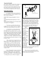
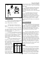
1234567890123456789012345678901212345678901234567890123456789012123456789012345678901234567890
1234567890123456789012345678901212345678901234567890123456789012123456789012345678901234567890
1234567890123456789012345678901212345678901234567890123456789012123456789012345678901234567890
1234567890123456789012345678901212345678901234567890123456789012123456789012345678901234567890
1234567890123456789012345678901212345678901234567890123456789012123456789012345678901234567890
1234567890123456789012345678901212345678901234567890123456789012123456789012345678901234567890
1234567890123456789012345678901212345678901234567890123456789012123456789012345678901234567890
1234567890123456789012345678901212345678901234567890123456789012123456789012345678901234567890
1234567890123456789012345678901212345678901234567890123456789012123456789012345678901234567890
1234567890123456789012345678901212345678901234567890123456789012123456789012345678901234567890
1234567890123456789012345678901212345678901234567890123456789012123456789012345678901234567890
1234567890123456789012345678901212345678901234567890123456789012123456789012345678901234567890
1234567890123456789012345678901212345678901234567890123456789012123456789012345678901234567890
1234567890123456789012345678901212345678901234567890123456789012123456789012345678901234567890
1234567890123456789012345678901212345678901234567890123456789012123456789012345678901234567890
1234567890123456789012345678901212345678901234567890123456789012123456789012345678901234567890
1234567890123456789012345678901212345678901234567890123456789012123456789012345678901234567890
1234567890123456789012345678901212345678901234567890123456789012123456789012345678901234567890
1234567890123456789012345678901212345678901234567890123456789012123456789012345678901234567890
1234567890123456789012345678901212345678901234567890123456789012123456789012345678901234567890
1234567890123456789012345678901212345678901234567890123456789012123456789012345678901234567890
1234567890123456789012345678901212345678901234567890123456789012123456789012345678901234567890
1234567890123456789012345678901212345678901234567890123456789012123456789012345678901234567890
TM
TomcoTechtips
ISSUE 32
rests on the pintle plate, or on the small metal
button cap on some models (Fig. 1). As the
OPERATING PARAMETERS
EGR pintle moves upward, so does the pintle
The PCM monitors the Manifold Absolute Pres- shaft of the EVP. This change in the EVP
sure (MAP) Sensor, the Engine Coolant Tempera- position, changes the voltage signal to the PCM.
ture (ECT) Sensor, the Throttle Position Sensor The PCM uses this voltage signal as a reference
(TPS) and the EGR Valve Position Sensor (EVP) of EGR flow.
EVP SENSOR VEHICLE
EVP SENSOR CONNECTOR
to calculate the correct amount of EGR flow
HARNESS CONNECTOR
EVP
required. The PCM then sends the appropriate
VREF
VREF
PIN A
SIGNAL
signals to the EGR control solenoid(s) so precise
EVP SIGNAL
PIN C
SIG. RTN
PIN B
control of EGR can occur.
FORD EGR VALVES
SIG. RTN
The PCM will not operate the EGR valve unless it
sees:
1.The engine warmed up to normal
operating temperature.
2.TPS at partial throttle.
3.TPS not at Wide Open Throttle (WOT).
4.MAP/MAF must be indicating light or
moderate load.
5.A certain amount of computer clock
time has to be elapsed.
EVP
The EVP is
the feedback to the
PCM of EGR
position. The
PCM monitors the
EVP signal to see
if the EGR valve is
opened the desired
amount.
As stated,
the tip of the EVP
VREF
5V
SIGNAL
SIG. RTN
PCM
Spring
Substrate
assy.
Housing assy.
EVP Mounting
Screws
EVP
EVP O-Ring
Upper Diaphragm
Housing
Return Spring
Diaphragm
Lower Diaphragm
Housing
Figure 1
Shaft / Wiper
assy. (Follows ECA
valve position)
Figure 2
The EVP is a three pin sensor (Fig 2).
One pin “A” supplies five volts from the computer. Another pin “B” is the ground for the
sensor, and the third pin “C” is the signal back to
the PCM. The EVP sensor functions the same as
most position sensors. A five volt reference is
sent across a resistive material. As the pintle on
the position sensor moves up, the five volts travel
across less of the resistive material. This allows
c Tomco, Inc. 1997
Tomco Tech Tips #32
more of the voltage to return to the computer. As
the pintle moves down, the five volts travel
across more of the resistive material so less of
the voltage returns to the PCM. (See Tech Tip
#19 for a more in depth look at EVP sensors).
EGRV
EGRC
Connection to
vacuum source
SOLENOID TESTING
A resistance check can be performed on
the EGR solenoid(s). A rule of thumb for resistance on these solenoids is:
EGRC/EGRV Solenoids should be 32 to 64
ohms.
EGR Shutoff Solenoids should be 51 to 108
ohms.
EVR Solenoids should be 20 to 70 ohms (100 to
135 ohms for 7.5L engines).
If you have any doubts about the ohm
reading you receive check your service manual
for the correct specifications for your vehicle.
A functional test can be performed on
most applications by using a Scan Tool. Enter
the Output State check and cycle the accelerator
pedal. This will turn all the solenoids on and off.
Using a DVOM monitor the voltage at the EGR
solenoid(s). They should toggle from a high
voltage to a low voltage. Typically this is stated
in the manuals and scan tools as above 10.5 volts
to below 2 volts.
If the voltage does not toggle make sure
that you have system voltage on the power side
of the connector. If system voltage is present
and the voltage does not cycle to the low side
check the connector and wiring to the PCM. If
the wiring and connector are okay the problem
may be in the pin at the PCM or the driver in the
computer itself.
Next, disconnect the vacuum connection
to the EGR shutoff, EGRC, or EVR solenoid.
Hook up a vacuum pump to the supply port of
the EGR shutoff, EGRC, or EVR solenoid (Fig.
3). During the test you will have to supply a
Connection to EGR Valve
Figure 3
constant vacuum to the port from the vacuum
pump. Hook up a vacuum gauge to the outlet
port of the solenoid. Have someone cycle the
accelerator pedal. The solenoid should hold
vacuum in one accelerator pedal position, and
release vacuum in the other. The release of
vacuum should be in less than 2 seconds.
If the
vacuum does not
Electronic Vacuum
Regulator (EVR)
release, or
releases too
CAP
slowly, check the
filter on the
FILTER
solenoid (Fig. 4,
EVR filter
shown). If this is
clogged it will
EVR
inhibit the
venting of the
solenoid. Some
of the EGRV
solenoids have a
vent hose that
goes up to the
Figure 4
throttle body.
Make sure this vacuum line and the port in the
throttle body are not plugged.
If the vents are okay and the vacuum
portion of the test just performed will not cycle
correctly, replace the solenoid(s).
Tomco Tech Tips #32
EGR/EVP TESTING
Figure 5
We have come up with a number of short
cuts in diagnosing the EGR valve and EVP
sensor. The procedure is as follows:
1. Disconnect the vacuum line to the
EGR valve, and connect a vacuum pump to it
(Fig. 5).
2. While holding your hand on the EGR
valve apply 10 inches of vacuum. If you feel the
valve pop or stick, the valve will have to be
serviced or replaced.
3. The valve should hold the 10 inches of
vacuum for at least one minute. If it doesn’t hold
vacuum, either the EGR diaphragm is leaking or
the EVP gasket is leaking. We have seen a
number of these gaskets leaking, causing intermittent codes.
4. If the valve checks out okay, test the
EVP sensor. Hook up a DVOM with a bar
graph, or preferably a labscope to the EVP signal
wire. Turn the Key On Engine Off (KOEO).
The starting voltage
% EGR
VOLTAGE
should be in the range
Black
Grey
shown in figure 6. If it
0
0.83
0.40
is not in range, the EGR
10
1.18
0.75
20
1.52
1.10
valve may have a piece
30
1.87
1.45
40
2.22
1.80
of carbon holding it
50
2.57
2.15
60
2.91
2.50
slightly open, or the
70
3.26
2.85
sensor may be bad.
80
3.61
3.20
90
3.95
3.55
Exercise the EGR valve
100
4.30
3.90
using a vacuum pump.
Figure 6
The base voltage should
return to the same value every time the vacuum is
released. If not it may be a sign of carbon buildup
on the pintle.
5. The sensor transition, while exercising
the EGR, should be smooth with no glitches on
the DVOM or the scope. If not, replace the
sensor. (See electronics 101 for a view of labscope
patterns.)
6. A resistance check can also be performed on the EVP. With the key in the off
position, remove the EVP connector. With an
acceptable meter, measure the resistance between
the VREF (Pin “A”) and EVP (Pin “C”) signal.
While exercising the EGR valve the resistance
should range from 5500 ohms to no less than 100
ohms.
VACUUM PROBLEMS
We have looked at the EGR solenoids and
the EGR valve and EVP for testing and problems.
But there could be a low vacuum problem. Check
the source vacuum and make sure there are no
leaks in the line to the solenoid. Also make sure
you check the line to the EGR valve itself.
In many cases the systems we have been
looking at start to open the EGR valve at 1 to 1.5
in HG and only need a maximum of 4 in HG to
open fully. When checking to see if opening an
EGR valve will make a difference in RPM, we
hook up a vacuum pump and apply 15 inches of
vacuum. This is almost 4 times as much vacuum
as the EGR valve will see under normal operating
conditions. This might cause us to miss a partially clogged or sticking EGR valve. Apply the
vacuum to the valve that it will see under normal
operation to test it more accurately.
CODES
Taking a careful look at and understanding the codes on the Ford EGR system can help
you chose the right diagnostic path. For instance
if a code 33 in the Key On Engine Running
(KOER) test mode has been set, this means that
the EVP voltage did not change when the EVR
was energized. If a code 84 during the KOEO
Tomco Tech Tips #32
test was not shown, we know that the EVR
functioned electrically. This means that the
computer sent out the signal. No sense in wasting time checking the signals from the computer.
Take time to read the code description and
definition, before you head off testing.
ELECTRONICS 101
Good EVP Pattern
Lets look at some of the waveforms
associated with these EGR systems. Figure 7
shows a pattern of a good and bad EVP signal.
As you can see we have set the scope voltage
scale at 1 volt per division and the time base at
250 ms per division. At these settings we can get
a good view of the EVP signal. We have the
(KOEO) and are monitoring the EVP signal as
we exercise the EGR valve. As you can see by
the arrow in the bad pattern we have a drop out
in the signal. This is our glitch in the EVP
signal.
Figure 8 shows the signal of the EVR
cycling on and off. As you can see we have set
the scope voltage at 5 volts per division and the
time base at a 5 ms per division. This pattern
was captured loading the engine in drive. The
Scanner read about a 40% duty cycle. The
maximum high of this signal is 13 volts while
the low voltage is 8.8 volts. If you look at the on
time of the signal (where it drops to a low voltage) it appears to be at the 40% duty cycle we
have seen on the Scanner.
Bad EVP Pattern
<
Figure 7
Figure 8