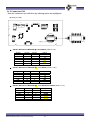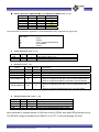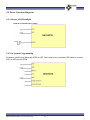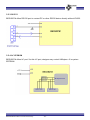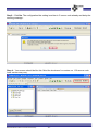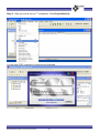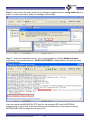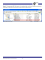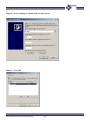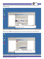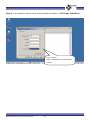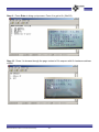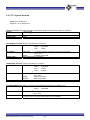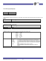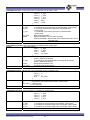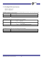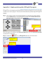
1
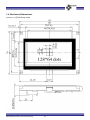
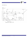
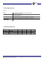
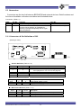
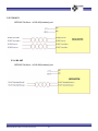
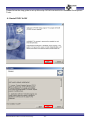
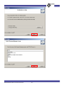
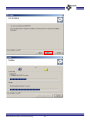
BEGV627M USER MANUAL z z z z z z z z z z LCD Embedded System Microchip PIC24FJ64GA002 MCU 64KB program flash/ 8KB SRAM I2C-EEPROM 64KB(Additional 64KB option) Dot Matrix 128*64 I2C-STN LCD w/ white LED backlight 1* RS232 + (shared RS232/RS422/RS485) 3 GPIOs 4-wire resistive touch panel Operating at 150 mA Free SDK Support Bolymin, Inc. www.bolymin.com.tw [email protected] Table of Content Chapter 1 Introduction ................................................................................................................................. 6 1.1 Features .......................................................................................................................................... 8 1.2 Board Layout ................................................................................................................................... 8 1.3 Block Diagram ................................................................................................................................. 9 1.4 Mechanical Dimensions ................................................................................................................ 10 1.5 Board Specifications ..................................................................................................................... 12 1.6 Ordering Information .................................................................................................................... 12 Chapter 2 Installation ................................................................................................................................. 13 2.1 Connectors .............................................................................................................................. 14 2.1.1 Connectors & Pin Definition of CN1 .................................................................................. 14 2.1.2 Connector CN2 ................................................................................................................... 15 2.2 Pin vs. Function Diagram .............................................................................................................. 17 2.2.1 Power/LCD/Backlight ......................................................................................................... 17 2.2.2 In‐System Programming .................................................................................................... 17 2.2.3 RS‐232 ................................................................................................................................ 18 2.2.4 I2C‐EEPROM ....................................................................................................................... 18 2.2.5 RS‐422 ................................................................................................................................ 19 2.2.6 RS‐485 ................................................................................................................................ 19 Chapter 3 MCU port mapping .................................................................................................................... 20 3.1 MCU Pin Configuration ................................................................................................................. 21 3.2 MCU Port Mapping ....................................................................................................................... 22 3.2.1 LCD Controller .................................................................................................................... 22 3.2.2 Touch Panel ....................................................................................................................... 22 3.2.3 RS‐232/RS‐422/RS‐485 ...................................................................................................... 22 3.2.4 Backlight PWM ................................................................................................................... 22 3.2.5 I2C‐EEPROM ....................................................................................................................... 22 3.2.6 General Purpose I/O .......................................................................................................... 22 Chapter 4 Software Development Tool & Utility ........................................................................................ 23 4.1 Install CCSC 4.093 ......................................................................................................................... 24 4.2 Install MPLAB ver 8.36 .................................................................................................................. 29 4.3 Install Bolymin Demo Code and library (SDK) .............................................................................. 36 4.4 Compile source code using MPLAB IDE ver 8.36 .......................................................................... 38 4.5 Programming HEX code using ICD3 .............................................................................................. 44 4.6 Running Hyper Terminal ............................................................................................................... 55 4.6 Running Hyper Terminal ............................................................................................................... 56 BEGV627M User Manual Ver.01 Preliminary ‐ 2 ‐ Chapter 5 Software Reference Manual ................................................................................................... 76 5.1 Setup development environment ................................................................................................ 77 5.2 Introduction of library .................................................................................................................. 79 5.2.1 Summary of modules of library ......................................................................................... 79 5.2.2 How to use library in application program ........................................................................ 80 5.3 Function Primitives ....................................................................................................................... 84 5.3.1 UART function .................................................................................................................... 84 5.3.2 I2C eeprom function ........................................................................................................... 86 5.3.3 LCD control function .......................................................................................................... 87 5. 3.4 Backlight PWM control function ....................................................................................... 89 5.3.5 Touch function ................................................................................................................... 90 Appendix A ‐ Simple operation guide of BTImg2LCD program .................................................................. 92 Appendix B ‐ Important Notice ................................................................................................................... 94 Appendix C ‐ Notes when running under Windows 7 ................................................................................ 95 BEGV627M User Manual Ver.01 Preliminary ‐ 3 ‐ Precaution FCC WARNING CAUTION This device is designed to meet the requirement in part 15 of the FCC rules. Operation is subject to conditions ruled under FCC part 15. BEGV627M User Manual Ver.01 Preliminary ‐ 4 ‐ Please check packing content upon receiving BEGV627M parcel, make sure that all materials and options are packed inside parcel according to your order. Packing Contents Check-List □ BEGV627M Embedded module □ Software Utility Disc □ ICD3 and ISP cable (option) □ MGI02-0$ ISP converter board (option) BEGV627M User Manual Ver.01 Preliminary ‐ 5 ‐ Chapter 1 Introduction Abstract This chapter is to offer you basic information regarding BEGV627M, to help you incorporate BEGV627M into your system. Contents include: 1-1 Features 1-2 Board Layout 1-3 Block Diagram 1-4 Mechanical Dimension 1-5 Board Specifications 1-6 Ordering information BEGV627M User Manual Ver.01 Preliminary ‐ 6 ‐ BEGV627M User Manual Ver.01 Preliminary ‐ 7 ‐ 1.1 Features BEGV627M is designed based on PIC24FJ64GA002 microprocessor and ST7588T LCD controller. Bolymin offers free Software Design Kit(SDK) for single-chip program development. Together with a 128x64 I2C STN LCD and LED backlight built-in, this all-in-one LCD embedded system BEGV627M offers designer a ideal solution to save hardware/software integration cost, space, and design time. Armed with RS232, RS422/485, I2C-EEPROM, 3 GPIOs, BEGV627M may communicate a variety of devices and peripherals. The BEGV627M is targeted for a industrial control panel for factory automation equipment, electronics instrument, HMI (human-machine interface), office automation equipment, medical equipment, parking system, ticketing system.. and so on. 64KB in-system programmable (ISP) flash, additional 64KB extendable, offers sufficient ROM size for designer to develop software and operate i2c-controlled dot matrix LCD and 3 GPIOs (IOA, IOB, IOC). BEGV627M is more than simply a Microchip development board, furthermore, it integrates display and I/O so that developers may start her application without the hassle of hardware integration. Henceforth, a quick time to market for customers’ innovative product is ensured.. 1.2 Board Layout This layout shows the location of each important IC, connector and jumper. Please refer to chapter 2 for further information on jumper and connector. (Drawing 1.2) 2 5 1 4 16 1 CN3 U7 CN5 8 4 A1 U5 U3 Y1 U6 1 U2 2 12 K1 1 3 CN2 11 1 CN1 BEGV627M V91 5 U1 A 1 :RS232 7 : CN2 - IO 2 :CN5 8 : RS422/485 K 6 7 3: Microprocessor 4 :EEPROM 5 :CN3 6 :CN1 – ISP BEGV627M User Manual Ver.01 Preliminary ‐ 8 ‐ 1.3 Block Diagram (Drawing 1.3) BEGV627M User Manual Ver.01 Preliminary ‐ 9 ‐ 1.4 Mechanical Dimensions (Drawing 1.4) (Front & top view) BEGV627M User Manual Ver.01 Preliminary ‐ 10 ‐ (Side & Back view) BEGV627M User Manual Ver.01 Preliminary ‐ 11 ‐ 1.5 Board Specifications (Table 1.5) MCU Memory Display Touch Panel Serial Ports High-performance, Low-power PIC 16-bit microprocessor Microchip PIC24FJ64GA002 64K Bytes In-System Programmable Flash 8K Bytes Internal SRAM 1 x 64K Bytes External I2C-EEPROM (Additional 64KB optional) Support I2C interface, resolution 128 x 64 monochrome STN LCD, with edge LED white backlight only; use ST7588t for LCD controller. Support four-wired resistive touch panel Support 1 x RS232 port, and 1 x RS232/RS422/RS485 co-shared port 1.6 Ordering Information (Table 1.6) Part No. Description RS232-A RS232-B BEGV627M Dual RS232 ☆ ☆ BEGV627M1 One RS232 ☆ BEGV627M2 One RS232/One RS422 ☆ BEGV627M3 One RS232/One RS485 ☆ Display: FSTN/Positive LCD,LED/White Backlight(Default) BEGV627M User Manual Ver.01 Preliminary ‐ 12 ‐ RS422 RS485 ☆ ☆ Chapter 2 Installation Abstract This chapter is to offer designer fundamental information of BEGV627M connectors, in order to help designer configure correct setting and connection between BEGV627M and system application. Contents include: 2-1 Connectors BEGV627M User Manual Ver.01 Preliminary ‐ 13 ‐ 2.1 Connectors Connectors are the key link between BEGV627M and external devices. Detail locations and functions of available connectors are tabled and illustrated below. Connectors: (Table 2.1) Label CN1 CN2 Pin No. 5 12 Function In-System Programming (ISP) Connector for GPIO, serial IO, /Reset, and Power. Connect CN2 of 627M to J2 of MGI$02 for powering up target board(627M) and for Hyper terminal operation. Item No. WFI-RT05-10Q DF11C-12DP-2V(57) 2.1.1 Connectors & Pin Definition of CN1 (Drawing 2.1CN1) Y1 1 CN3 16 U7 CN5 4 U5 U3 A1 U6 1 U2 1 2 12 K1 1 z z CN2 11 1 CN1 K CN1 Pin Definition (Table 2.1.1a) Pin No. 1 Signal /Reset 2 A Description MPLAB controllable voltage – power target device from ICD3 (ranges from 3 to 3.5 volt, see page 48) 3 GND 4 PGD Connect PIC24FJ64GA002 port RP0/PGD1,#1 5 PGC Connect PIC24FJ64GA002 port RP1/PGC1,#2 ISP Power & Ground (Table 2.1.1b) Signal VCC GND z BEGV606M 5 U1 A 5 Type Pin No. P P 2 3 Description Logic power supply (+3.3V) Logic power supply (ground) ISP Power & Ground (Table 2.1.1c) Signal /Reset PGD PGC Type Pin No. I Bi Bi 1 4 5 BEGV627M User Manual Ver.01 Preliminary Description Auxiliary moment reset for external input ISP Programming Data ISP Programming Clock ‐ 14 ‐ CN1 2.1.2 Connector CN2 Note the variance in pin definition by ordering option as highlighted. (Drawing 2.1CN2) Y1 16 1 CN3 U7 CN5 4 U5 U3 A1 U6 1 U2 12 2 11 1 2 12 K1 1 z K CN2 Pin Definition of BEGV627M - Dual RS232 (Table 2.1.2a) Pin No 2 4 6 8 10 12 Pin No. 1 3 5 7 9 11 Signal VDD NC NC TX1 RX1 /RST CN2 Pin Definition of BEGV627M1 - One RS232 (Table 2.1.2b) Signal GND TX0 RX0 IOA IOB IOC z CN2 1 CN1 Signal GND TX0 RX0 IOA IOB IOC z BEGV627M V91 11 5 U1 A Pin No 2 4 6 8 10 12 Pin No. 1 3 5 7 9 11 Signal VDD NC NC NC NC /RST CN2 Pin Definition of BEGV627M2 - One RS232/One RS422 (Table 2.1.2c) Signal GND TX0 RX0 IOA IOB IOC Pin No 2 4 6 8 10 12 Pin No. 1 3 5 7 9 11 BEGV627M User Manual Ver.01 Preliminary Signal VDD 422RP 422RN 422TP 422TN /RST ‐ 15 ‐ CN2 z CN2 Pin Definition of BEGV627M3 - One RS232/One RS485 (Table 2.1.2d) Signal GND TX0 RX0 IOA IOB IOC Pin No 2 4 6 8 10 12 Pin No. 1 3 5 7 9 11 Signal VDD NC NC 485P 485N /RST Here summarize all CN2 pins applicable on 627M embedded system categorized by signal type. Pin Types I O Bi U P z Power & Ground (Table 2.1.2e) Signal VDD GND z =Input =Output =Input / Output (Bi-Directional) =User defined =Power Type Pin No. P P 1 2 Description Logic power supply (+5V) Logic power supply (ground) Serial I/O (Table 2.1.2f) Signal Type Pin No. RX0 TX0 422RP 422RN I O I I 6 4 3 5 422TP/485P/TX1 Bi 7 422TN/485N/RX1 Bi 9 z Description Receiver of first RS232 with driver Transmitter of first RS232 with driver no inverting receiver of RS422 inverting receiver of RS422 When is configured as RS422 it act as no inverting transmitter, When is configured as RS 485 it acts as positive differential IO. When is configured as RS232 Transmitter of second RS232. When is configured as RS422 it acts as inverting transmitter, When is configured as RS 485 it acts as negative differential IO. When is configured as RS232 Receiver of second RS232. General purpose I/O (Table 2.1.2g) Signal /Reset IOA IOB IOC Type Pin No. I U U U 11 8 10 12 Description Auxiliary moment reset for external input I/O port (PIC24FJ64GA002 port RP4, #8) I/O port (PIC24FJ64GA002 port RP7,#13) I/O port (PIC24FJ64GA002 port RP11,#19) Note that there is a series resistor of 100 ohm on the 3 GPIOs, also with ESD protection circuit. The RS-232 voltage is elevated from CMOS 3.3v to TTL 5 volt level through ICL3232. BEGV627M User Manual Ver.01 Preliminary ‐ 16 ‐ 2.2 Pin vs. Function Diagram 2.2.1 Power/LCD/Backlight Diagram of system power supply. 2.2.2 InSystem Programming Customer need to buy Microchip ICD3 for ISP. Also need to buy converter ISP cable to connect ICD3 to ISP port on 627M. BEGV627M User Manual Ver.01 Preliminary ‐ 17 ‐ 2.2.3 RS232 BEGV627M offers RS-232 port to contact PC or other RS232 device directly without ICL232. 2.2.4 I2CEEPROM BEGV627M offers I2C port. Via this I2C port, designer may control 64Kbytes x 2 in-system EEPROM. BEGV627M User Manual Ver.01 Preliminary ‐ 18 ‐ 2.2.5 RS422 BEGV627A offers 1 x RS-422(isolated) port. 2.2.6 RS485 BEGV627A offers 1 x RS-485(isolated) port. BEGV627M User Manual Ver.01 Preliminary ‐ 19 ‐ Chapter 3 MCU port mapping Abstract This chapter explains PIC24FJ64GA002 MCU pin configuration and port mapping toward key elements such as LCD, Touch Panel, RS-232, RS-422, RS-485, LED Backlight, I2C- EEPROM and 3 General purpose I/O. BEGV627M User Manual Ver.01 Preliminary ‐ 20 ‐ 3.1 MCU Pin Configuration (Drawing 3.1, PIC24FJ64GA002) BEGV627M User Manual Ver.01 Preliminary ‐ 21 ‐ 3.2 MCU Port Mapping 3.2.1 LCD Controller (Table 3.2a) MCU PIC24FJ64GA002 RP2/SDA2, #3 RP3/SCL2, #4 TDO/SDA1/RP9, #15 LCD Controller LSDA LSCL LCD RST 3.2.2 Touch Panel (Table 3.2b) MCU PIC24FJ64GA002 AN0, #27 AN1, #28 AN11, #21 AN12, #20 Touch Panel X1 (CN3#1) Y1 (CN3#2) X2 (CN3#3) Y2 (CN3#4) 3.2.3 RS232/RS422/RS485 (Table 3.2c) MCU PIC24FJ64GA002 RP14, #22 RP15, #23 RP6/PGC3, #12 RP5/PGD3, #11 RS-232/422/485 RX0 (CN2#6) TX0 (CN2#4) 422TN/485N/RX1 (CN2#9) 422TP/485N/TX1 (CN2#7) (Table 3.2d) MCU PIC24FJ64GA002 RA4/T1CK, #9 RS-485 Enable RS-485 3.2.4 Backlight PWM (Table 3.2e) MCU PIC24FJ64GA002 RP10, #18 LED backlight Backlight PWM 3.2.5 I2CEEPROM (Table 3.2f) MCU PIC24FJ64GA002 RP2/SDA2, #3 RP3/SCL2, #4 RP8/TCK, #14 EEPROM/ I2C EEPROM SDA EEPROM SCL EEPROM WP 3.2.6 General Purpose I/O (Table 3.2g) MCU PIC24FJ64GA002 RP4, #8 RP7, #13 RP11, #19 General Purpose I/O IOA(CN2#8) IOB(CN2#10) IOC(CN2#12) BEGV627M User Manual Ver.01 Preliminary ‐ 22 ‐ Chapter 4 Software Development Tool & Utility Abstract This chapter explains PIC24FJ64GA002 MCU software development tool Microchip ICD3 and Bolymin free software utilities. BEGV627M User Manual Ver.01 Preliminary ‐ 23 ‐ Please follow the step guide to set up Microchip PIC24FJ64GA002/004 Software Development Tools. 4.1 Install CCSC 4.093 BEGV627M User Manual Ver.01 Preliminary ‐ 24 ‐ BEGV627M User Manual Ver.01 Preliminary ‐ 25 ‐ BEGV627M User Manual Ver.01 Preliminary ‐ 26 ‐ Click Next to complete installation of CCSC 4.093 . BEGV627M User Manual Ver.01 Preliminary ‐ 27 ‐ Now check the CCSC complier version CCSC version is 4.093. BEGV627M User Manual Ver.01 Preliminary ‐ 28 ‐ 4.2 Install MPLAB ver 8.36 Designers may download software development too MPLAB ver 8.36 from the following URL: http://www.microchip.com/stellent/idcplg?IdcService=SS_GET_PAGE&nodeId=1406&dD ocName=en023073 http://ww1.microchip.com/downloads/en/DeviceDoc/MPLAB_IDE_8_36.zip or from BOLYMIN utility disk. BEGV627M User Manual Ver.01 Preliminary ‐ 29 ‐ BEGV627M User Manual Ver.01 Preliminary ‐ 30 ‐ BEGV627M User Manual Ver.01 Preliminary ‐ 31 ‐ BEGV627M User Manual Ver.01 Preliminary ‐ 32 ‐ BEGV627M User Manual Ver.01 Preliminary ‐ 33 ‐ Click No. Bolymin driver supports only CCSC v4.093 binary object file and henceforth user have to apply the same compiler such that binary objects can be linkable. BEGV627M User Manual Ver.01 Preliminary ‐ 34 ‐ Note the MPLAB IDE v8.36 is added on the desktop. BEGV627M User Manual Ver.01 Preliminary ‐ 35 ‐ 4.3 Install Bolymin Demo Code and library (SDK) Here is the URL to download latest version of source code and libraries with pre-configured compile environment. http://www.bolymin.com.tw/embedded/BEGV627M.rar Decompress the rar file into c:\BEGV627M and here is the file listing – ¾ C:\BEGV627M folder contains version info README file and BTImg2LCD, a bitmap font conversion utility program. Please refer to last appendix for step guide. ¾ Header file (*.h) and linkable object files (*.o) – use default folder as follows : BEGV627M User Manual Ver.01 Preliminary ‐ 36 ‐ ¾ Working folder contains all demo source code , intermediate files, and HEX codes BEGV627M User Manual Ver.01 Preliminary ‐ 37 ‐ 4.4 Compile source code using MPLAB IDE ver 8.36 Please follow the step guide to make your 1st successful compilation. Step 1 - click left icon on desktop or Start→All programs→Microchip→MPLAB IDE Step2 – Click File-Open Workspace – browse into c:\BEGV627M\prg folder , and open BEGV627_DTP.mcw BEGV627M User Manual Ver.01 Preliminary ‐ 38 ‐ Step3 – Click No. The configuration bits setting is written in C source code already and belay the warning message.. Step 4 – Your screen should be like this. Mind the checksum for version ver 1.00 source code. Later version may vary. BEGV627M User Manual Ver.01 Preliminary ‐ 39 ‐ Step 5 – Now you are all set for 1st compilation. Click Project-Build all. You will see CCSC compiling in progress as illustrated. BEGV627M User Manual Ver.01 Preliminary ‐ 40 ‐ Step 6 – Here comes the same old warning message complaining about configuration bit as in step 2. For the same token, belay the message and click No. Step 7 – check the compilation result – go to output window by clicking Windows-Output, maximize it, and read the last line – BUILD SUCCEEDED. Congratulations for what you have achieved this far. Also note that a new BEGV627M_DTP.hex file, the program HEX code for EEPROM programming, is generated. In the next section, we will introduce you the steps for writing EEPROM HEX code to target device using ICD3. BEGV627M User Manual Ver.01 Preliminary ‐ 41 ‐ Step 8 - The generated HEX file locates in the working folder as follows. Double check the time stamp will be identical to the build time at the last line of above screen. BEGV627M User Manual Ver.01 Preliminary ‐ 42 ‐ Advanced users may start playing with source code, change “Demo“ into “Moon“ for instance. Then recompile to generate new program HEX and write it into EEPROM. You will see the change takes effect as expected. BEGV627M User Manual Ver.01 Preliminary ‐ 43 ‐ 4.5 Programming HEX code using ICD3 6 5 7 3 4 1 2 ** Inside ICD3(1), designer will get DVD, ICD3 device(2), RJ-45 cable(3) and USB cable(4). Please purchase MGI02-0$ (4) , a Bolymin proprietary converter board to interface between ICD3 and target device, BEGV627M (5). You need a RS-232 straight-through cable (pin 2,,3,,5 used) for hyper terminal operation by PC (Windows XP recommended). Prepare a DC 5v/500mA adapter to connect to MGI02-0$ ((4) to supply power to target device. User may custom may consider using 5volt from PC-USB(7) as power source. ICD3 is always self-powered by PC-USB cable(2). Note to remove 5 volt power from target board before ICD3 is connected to MGI02-0$. Configuration for EEPROM programming – Apply only connection marked with blue. BEGV627M User Manual Ver.01 Preliminary ‐ 44 ‐ Here are requirements for HEX code EEPROM programming- Hardware Requirements # HW Item Qty Description 1 PC with COM port 1 Requires RS-232 port 2 Programmer-ICD3 1 3 Converter board 1 MGI02-0$ 4 USB cable 1 Type A maleÅ---Æ Type B male 5 RS-232 ext. cable 1 Straight through RS-232 extension cable DB-9 maile-DB-9 male; or use a USB-serial cable Software Requirements # SW item Qty Description 1 Programming IDE 1 MPLAB IDE 4.83 by Microchip 2 Terminal Emulation 1 Hyper Terminal (XP build in) 3 Bolymin DEMO program 1 Demo source code, DLL, and program HEX BEGV627M User Manual Ver.01 Preliminary ‐ 45 ‐ Step 1 - Connect 1 RJ-11 and 2 USB cable to 3 ICD3 3 2 1 Step 2 - Connect 1 RJ-11 and cables to 2 MGI02-0$ 2 1 Step 3 - Connect MGI02-0$ to PC using a RS-232 cable BEGV627M User Manual Ver.01 Preliminary ‐ 46 ‐ Step 4 - Connect MGI02-0$ to BEGV627M. BEGV627M User Manual Ver.01 Preliminary ‐ 47 ‐ Step 5 - Open MPLAB IDE v8.36,Click on Configure-Select Device Step 6 - Select PIC24FJ64GA002 as Device, then click OK. BEGV627M User Manual Ver.01 Preliminary ‐ 48 ‐ Step 7 – click Programmer-Select Programmer - 5 MPLAB ICD3. Note target device is not powered as yet. Therefore there is no display on LCD. BEGV627M User Manual Ver.01 Preliminary ‐ 49 ‐ Step 8 - Change programmer settings to use ICD3 as power supply to target device. Click Programmer-Settings, select Power tab, check on Power target circuit from MPLAB ICD3. Then click OK. BEGV627M User Manual Ver.01 Preliminary ‐ 50 ‐ Step 9 - As soon as the power setting is done, note target device is now powered by ICD3 and LCD will display the default demo program as illustrated. Also on ICD3, observe the blue Active LED is on. Notice a Device ID Revision will display on the last line of output window. BEGV627M User Manual Ver.01 Preliminary ‐ 51 ‐ Step 10 - User may try toggle the power target device from ICD3 and observe the output windows message as follows, blue LED on ICD3 is off – 627M LCD display is off. Now switch back to powered by ICD3. BEGV627M User Manual Ver.01 Preliminary ‐ 52 ‐ Step 11 - Select the Hex code for programming. Browse into c:\BEGV627M\prg folder BEGV627M User Manual Ver.01 Preliminary ‐ 53 ‐ And select the HEX file Step 12 - Click on icon to program the program HEX code. Observe the output windows should display Programming/Verify complete upon completion of a successful HEX programming. BEGV627M User Manual Ver.01 Preliminary ‐ 54 ‐ Step 13 - After HEX code programming, target device is reset and BEGV627M LCD should display as follows: For more detail operation about ICD3, please also refer to Micrcochip URL: http://www.microchip.com/stellent/idcplg?IdcService=SS_GET_PAGE&nodeId=1406&dDocNa me=en537580&redirects=icd3 In case user wanted to change to folder structure, remember to change .mcp file with appropriate folder name. Traverse through the .mcp and modify target folder as appropriate. BEGV627M User Manual Ver.01 Preliminary ‐ 55 ‐ 4.6 Running Hyper Terminal After EEPROM programming is done, disconnect ICD3, and power target device using 5Vdc. Now connect RS-232 from convert board to XP/Win7 PC. (Photo applies configuration #1, see next page) . Connect CN2 of 627M to J2 of MGI$02 converter board. At least 4 pins are required as marked. J2# CN2 Signal CN2 # CN2 # CN2 Signal 2 GND 2 1 VDD 4 TX0 4 3 NC 3 RX0 6 5 NC IOA 8 7 TX1 IOB 10 9 RX1 IOC 12 11 /RST BEGV627M User Manual Ver.01 Preliminary ‐ 56 ‐ J2# 1 Configuration #1 for hyper terminal operation – As highlighted pink, apply External DC 5v , only J2-CN2 connection needed, and RS-232 to support hyper terminal operation from XP PC end. Configuration #2 for hyper terminal operation – Alternative connection is have target device draw power directly from ICD3. Note external 5Vdc should NOT be connected. Remember to change ICD3 setting using MPLAB as stated at step 10 of Chapter 4-5. Either configuration works, configuration #1 might be easier if there is no source code change involved. Also configuration #1 provides a 5 volt rather than 3.3volt on target device. BEGV627M User Manual Ver.01 Preliminary ‐ 57 ‐ Use Hyper terminal to operate the demo program BEGV627M supports touch panel. Bolymin calibrated the touch panel before shipping out. User may try demo program by using touch panel as input device. Please use hyper terminal for terminal emulation and kernel debugging. The PC keyboard can then emulate as a input device to 627M. Here is the step guide - Step 1 - Make sure you have at least one RS-232 serial port available. The following example shows a COM3 is available. BEGV627M User Manual Ver.01 Preliminary ‐ 58 ‐ Step 2 - On XP PC: StartÆAll programsÆTelecommunicationÆHyperTerminal (or Windows+R, hypertrm) Step 3 - Click No if you do not use hyper terminal to telnet to UNIX host. BEGV627M User Manual Ver.01 Preliminary ‐ 59 ‐ Step 4 – enter country and area code as appropriate. Step 5 – Click OK. BEGV627M User Manual Ver.01 Preliminary ‐ 60 ‐ Step 6 - Enter the file name to store the hyper terminal settings. System will auto add a .ht extension name. Please define a name and choose a icon for this connection, and click Yes to continue. Step 7 -Select COM port as appropriate. Hyper terminal will pull down only valid COM ports. Choose a suitable COM port, and click Yes to continue. BEGV627M User Manual Ver.01 Preliminary ‐ 61 ‐ Step 8 - It is required to set the serial communication as follows – 115200 bps, N/8/1/None. Key in COM port setting:115200/8/No/1/No, and click Yes to continue. BEGV627M User Manual Ver.01 Preliminary ‐ 62 ‐ Step 9 – Press Enter to bring up top menu. Press 1 to get to i2c (24c512) Step 10 - Press 1 to browse through the page content of i2c-eeprom with i2c hardware address of $A2. BEGV627M User Manual Ver.01 Preliminary ‐ 63 ‐ Step 11 - Here is I2c-eeprom content listing starting from 0x0 to 0xff. Step 12 - Press 2 to write 0xAA into whole page. BEGV627M User Manual Ver.01 Preliminary ‐ 64 ‐ Step 13 -Press 3 – write 0 to the whole page via i2c to eeprom (starting from $0 to $00ff) Press N for next page, P for previous page to confirm the change. BEGV627M User Manual Ver.01 Preliminary ‐ 65 ‐ Step 14 - Press N to browse content of next page, which is with a starting address of 0x100 . Step 15 -Press P to browse content of previous page, which is with a starting address of 0x00. Confirm that previous write operation of 0x00(data) to 0x00 (address) page is indeed succssful. Press 0 0 to return to top menu. BEGV627M User Manual Ver.01 Preliminary ‐ 66 ‐ Step 16 -Press 3 to enter LCD test. There are 8 patterns available for the demo. Step 17 - Cycle through 1 to 8 to observe the various demo patterns as shown next page. Now press 0 to return to top menu. BEGV627M User Manual Ver.01 Preliminary ‐ 67 ‐ 1. Full on 2. Vertical line 3. Horizontal line 4.Half blocks 5. Cross dots (2x2 checker board pattern) 7. Picture pattern #1 BEGV627M User Manual Ver.01 Preliminary 6. Show characters 8. Picture Pattern #2 ‐ 68 ‐ Step 18 - Press 4 to enter brightness test. Step 19 -Press 1 to increment brightness level by 5. The brightness ranges from 0 to 100 with a step of 5 for each adjustment. BEGV627M User Manual Ver.01 Preliminary ‐ 69 ‐ Step 20 -Now try press 2 2 to reduce brightness level by 10. 0 to return to top menu, 5 to enter Touch BEGV627M User Manual Ver.01 Preliminary ‐ 70 ‐ Step 21 -Now use light pen to touch from left to right screen, you will observe the DX value increases as the click goes east-bound. Step 22 -Use light pen to touch from top to bottom, note the DY value increase as the click goes south-bound. BEGV627M User Manual Ver.01 Preliminary ‐ 71 ‐ Step 23 - 0 to return to top menu, 6 to calibrate (5-point) Press and hold box with cross for around 2 seconds by the order to center, upper-left, upper-right, lower-right, lower-left. After this calibration, demo program auto return to top menu. 2nd CP – upper left. BEGV627M User Manual Ver.01 Preliminary ‐ 72 ‐ 3rd CP – upper right. 4th CP – lower right BEGV627M User Manual Ver.01 Preliminary ‐ 73 ‐ 5th CP –lower left Automatically return to top menu upon completion of 5 CP calibrations. BEGV627M User Manual Ver.01 Preliminary ‐ 74 ‐ Step 24 – Close hyper terminal . Click yes to save into c3.ht the serial communication protocol (com3,115200bps, N/8/1). Next time open the hypertrm, simply click file-open and select c3.ht. BEGV627M User Manual Ver.01 Preliminary ‐ 75 ‐ Chapter 5 Software Reference Manual Abstract This chapter introduces all functions of device driver library for BEGV627M device and describes major issues about application program development. BEGV627M User Manual Ver.01 Preliminary ‐ 76 ‐ 5.1 Setup development environment Bolymin recommends to use the Integrated Development Environment (IDE) provided by Microchip, MPLAB IDE v8.36, and CCS C complier v4.093 to develop new application software. Here is the step guide to set up the development environment: Step 1 - Install CCS C complier v4.093 – refer to 4-1 Step 2 - Install MPLAB IDE v8.36 – refer to 4-2 Step 3 - Open MPLAB 8.36 ,then select Project-Set Language Tool Locations… to confirm default complier is CCS C v4.093 complier. User may not need to change the setting if she follows chapter 4.1and 4.2 installation procedure since installation program will automatically configure accordingly. BEGV627M User Manual Ver.01 Preliminary ‐ 77 ‐ Step 4 - Select Project-Project Wizard… to create a new project and start development. Click Next to skip the Welcome screen. NOTE: 1. After creating a project, user need to create an empty file by the name of project in the directory of project so that the HEX file could be created successfully. For example, Project DTP_627M needs a file named DTP_627M in the same directory. 2. Please include config.h for all *.C file. 3. We need to select device type of MCU while creating new project at the screen shown as follows: Step 5 - For BEGV627M , select PIC24FJ64GA002 as device. BEGV627M User Manual Ver.01 Preliminary ‐ 78 ‐ 5.2 Introduction of library Bolymin supports device driver library for application development of BEGV627M. Refer to the following figure for program hierarchy. Application program Customer developed program Device driver library Hardware (BEGV627M device) 5.2.1 Summary of modules of library BEGV627M driver library consists of 5 modules. There are several functions for each module. Following table is a summary of modules in library: Module name Description Header file and compiled object UART Include all functions about operation of UART port. uart.h I2C eeprom Read and write functions for I2C eeprom. I2c.h I2c.o I2ceeprom.h I2ceeprom.o LCD display LCD display fuctions ST7588T.h PWM for backlight Set or get current PWM value to adjust backlight of LCD. bklight_pwm.o bklight_pwm.h Touch Touch panel touch.h BEGV627M User Manual Ver.01 Preliminary ‐ 79 ‐ uart.o ST7588T.o touch.o 5.2.2 How to use library in application program Please follow below steps to use device library provided by Bolymin: Step1 –refer to 4.2 and 4.3 for Bolymin library and demo code installation. Follow 4.4 to step 4. Step 2.- Select Project-Build Options…-Project. BEGV627M User Manual Ver.01 Preliminary ‐ 80 ‐ Step 3 – Set Include Search Path to the path of header files of library provided by Bolymin. Click on New to bring up a new row and a folder browse button. Click on browse button to bring up a Browse For Folder dialog windows to add it to include search path. BEGV627M User Manual Ver.01 Preliminary ‐ 81 ‐ Step 4 - Click Object File of mcw window shown below by right-clicking mouse and select Add Files… to bring up Add Files to Project windows. Click on the .o object file and click open button to add necessary object files into your project. Move into the directory of object files of device library and select necessary object files. BEGV627M User Manual Ver.01 Preliminary ‐ 82 ‐ Step 5 - After clicking Open button of Add files to Project dialog, you can see all necessary object files have been add into your project, like below picture. Now you can start to develop your application program. All necessary object files have been add into your project BEGV627M User Manual Ver.01 Preliminary ‐ 83 ‐ 5.3 Function Primitives 5.3.1 UART function Header file : uart.h Object file : uart.o uartInit Function: Initial UART. void uartInit( Syntax uint8_t byPort, uint32_t uBaudrate, uint8_t byParity, uint8_t uDatabit, uint8_t uStopbit, uint8_t nTxMode ); byPort UART_PORT0 – 1st Uart port Parameters UART_PORT1 – 2nd Uart port nBaudrat Baud rate, ex: 9600. byParity Parity Check, `N' – None, `E' – EVEN, `O' - ODD. uDatabit data bit , 5 ~ 8. uStopbit data bit , 1 ~ 2. nTxMode Transmission Mode. 0 or FALSE – RS232. 1 or TRUE – RS485 or RS422. None. Return value uartSetBaudRate Function: Set up baud rate for assigned UART port void uartSetBaudRate( Syntax uint8_t byPort, uint32_t uBaudrate ); byPort UART_PORT0 – 1st Uart port Parameters UART_PORT1 – 2nd Uart port nBaudrate Baud Rate, ex: 9600. None. Return value uartSendByte Function: Send 1 byte from assigned UART port void uartSendByte( Syntax uint8_t byPort, uint8_t txData ); byPort UART_PORT0 – 1st Uart port Parameters UART_PORT1 – 2nd Uart port txData Byte to be sent. None. Return value BEGV627M User Manual Ver.01 Preliminary ‐ 84 ‐ uartSendString Function: Send string from assigned UART port void uartSendString( Syntax uint8_t byPort uint8_t* str ); byPort UART_PORT0 – 1st Uart port Parameters UART_PORT1 – 2nd Uart port str Memory pointer of string to be sent, ending with 0. None. Return value uartSendBuffer Function: Send buffer from assigned UART port void uartSendBuffer( Syntax uint8_t byPort, uint8_t* buffer, uint16_t nBytes ); byPort UART_PORT0 – 1st Uart port Parameters UART_PORT1 – 2nd Uart port buffer Memory pointer of data to be sent nBytes Bytes of data to be sent None. Return value uartReceiveByte Function: Read 1 byte data from assigned UART port uint8_t uartReceiveByte( Syntax uint8_t byPort, uint8_t* rxData ); byPort UART_PORT0 – 1st Uart port Parameters UART_PORT1 – 2nd Uart port rxData buffer used to put received data Return value TRUE – UART port receive data and put in rxData FALSE – There is no data in assigned UART port. uartReceiveBufferIsEmpty Function: Check if the receive buffer of assigned UART port is empty or not void uartReceiveBufferIsEmpty( Syntax uint8_t byPort ); byPort UART_PORT0 – 1st Uart port Parameters UART_PORT1 – 2nd Uart port Return value TRUE – The receive buffer of assigned UART port is empty. FALSE – There is data in receive buffer of assigned UART port uartFlushReceiveBuffer Function: Clear receive buffer of assigned UART port void uartFlushReceiveBuffer( Syntax uint8_t byPort ); byPort UART_PORT0 – 1st Uart port Parameters UART_PORT1 – 2nd Uart port None. Return value BEGV627M User Manual Ver.01 Preliminary ‐ 85 ‐ 5.3.2 I2C eeprom function Header file : i2ceeprom.h object file : i2c.o, i2ceeprom.o i2cInitial Function: Initial I2C functions. User should call this function before using I2C functions. void i2cInitial( Syntax ); None. Parameters None. Return value i2cReadByte Function: Read 1 byte data from I2C eeprom. uint8_t i2cReadByte( Syntax uint8_t uDevAddr, int16 nAddr ); uDevAddr I2C device address. (address of eeprom on board are: Parameters A2hex, A4hex. nAddr Address will be read. Data reading from I2C eeprom. Return value i2cWriteByte Function: Write 1 byte data to I2C eeprom. void i2cWriteByte( Syntax uint8_t uDevAddr, int16 nAddr, uint8_t byData ); uDevAddr I2C device address.(address of eeprom on board are: Parameters A2hex, A4hex. nAddr Address to write in . byData Data to be written. None. Return value i2cIsEEPROMExist Function: Check if the specified address eeprom is available or not. uint8_t i2cIsEEPROMExist ( Syntax uint8_t uDevAddr, ); uDevAddr I2C device address.(address of eeprom on board are: Parameters A2hex, A4hex. TRUE: Eeprom with uDevAddr address is available. Return value FALSE: Eeprom with uDevAddr address is not available. BEGV627M User Manual Ver.01 Preliminary ‐ 86 ‐ 5.3.3 LCD control function Device Header file Object file BEGV627M ST7588T.h ST7588T.o lcdInit Function: Initialize all parameters of LCD display. User should call this function before use functions of LCD display. void lcdInit ( Syntax ); None. Parameters None. Return value lcdDisplayClr Function: Clear screen. lcdDisplayClr( Syntax ); None. Parameters None. Return value lcdDraw Function: Draw input binary picture on specified area of graphic area. void lcdDraw ( Syntax uint16_t x_start, uint16_t y_start, uint16_t x_end, uint16_t y_end, uint8_t * pic_data, uint8_t mode ); x_start X coordinate of the top-left point of input picture. (UNIT=pixel) Parameters y_start Y coordinate of the top-left point of input picture. (UNIT=pixel) x_end X coordinate of the bottom-right point of input picture. (UNIT=pixel) y_end Y coordinate of the bottom-right point of input picture. (UNIT=pixel) pic_data Bit map data will be drawn. Input 0 will reverse pixels of specified area. mode DRAW_NORMAL:Draw the picture normally. DRAW_REVERSE : Reverse the picture and then draw the picture. None. Return value BEGV627M User Manual Ver.01 Preliminary ‐ 87 ‐ lcdFillByte Function: Fill input byte value on specified area of graphic layer. void lcdFillByte ( Syntax uint16_t x_start, uint16_t y_start, uint16_t x_end, uint16_t y_end, uint8_t data, uint8_t mode ); x_start X coordinate of the top-left point of specified area. (UNIT=pixel) Parameters y_start Y coordinate of the top-left point of specified area. (UNIT=pixel) x_end X coordinate of the bottom-right point of specified area. (UNIT=pixel) y_end Y coordinate of the bottom-right point of specified area. (UNIT=pixel) pic_data Byte value will be filled. Mode DRAW_NORMAL: Fill input value normally. DRAW_REVERSE : Reverse the input value and then fill it on the specified area None. Return value lcdPrintString Function: Print input string to specified location of text layer. void lcdPrintString ( Syntax uint8_t x_start, uint8_t y_start, char * string, uint8_t str_count ); x_start X coordinate of start location that input string will be printed. Parameters (UNIT= character=8*8 pixel) y_start Y coordinate of start location that input string will be printed. (UNIT= character=8*8 pixel) string string will be printed to LCD str_count character count of input string None. Return value lcdDrawBit Function: ON/OFF the pixel on specified location of graphic layer. void lcdDrawBit ( Syntax uint16_t x, uint16_t y, char bit_value ); x X coordinate of the location will be drawn. (UNIT=pixel) Parameters y Y coordinate of the location will be drawn. (UNIT=pixel) bit_value 1 : ON the pixel 0 : OFF the pixel None. Return value lcdDrawRect Function: Draw rectangle by single line on graphic layer. void lcdDrawRect ( Syntax uint16_t x_start, uint16_t y_start, uint16_t x_end, uint16_t y_end, ); x_start X coordinate of the top-left point of rectangle. (UNIT=pixel) Parameters y_start Y coordinate of the top-left point of rectangle. (UNIT=pixel) x_end X coordinate of the bottom-right point of rectangle. (UNIT=pixel) y_end Y coordinate of the bottom-right point of rectangle. (UNIT=pixel) None Return value BEGV627M User Manual Ver.01 Preliminary ‐ 88 ‐ 5. 3.4 Backlight PWM control function Header file : bklight_pwm.h object file : bklight_pwm.o bklPWM_Init Function: Initialize all parameters of backlight PWM control function. User should call this function before use backlight PWM control functions. void bklPWM_Init ( Syntax ); None. Parameters None. Return value bklSetBrightness Function: Set current brightness value of backlight. void bklSetBrightness ( Syntax int8_t brightness ); Brightness New brightness value Parameters 0 – OFF backlight 1~100 – Control the brightness of backlight None. Return value bklGetBrightness Function: Get current brightness value of backlight uint8_t bklGetBrightness ( Syntax ); None. Parameters Current brightness value of backlight. (0 ~ 100) Return value BEGV627M User Manual Ver.01 Preliminary ‐ 89 ‐ 5.3.5 Touch function Header file : touch.h object file : touch.o touchInit Function: Initial Touch panel. void touchInit( Syntax int int res_x, res_y, ); Parameters Return value res_x res_y None. X resolution of touch panel. Y resolution of touch panel. touchGet Function: Read touch data from touch panel uint8_t touchGet( Syntax uint16_t * pX, uint16_t * pY uint8_t is_calibration ); pX X Coordinate value from touch data Parameters pY Y Coordinate value from touch data is_calibration Flag to indicate current operation is for calibration or not. TRUE There is data from touch panel and the data is saved at pX and Return value pY. FALSE There is no data from touch panel. setCalibrationMatrix Function: Set Calibration calculation matrix void setCalibrationMatrix( Syntax POINT * ptDisplay, POINT * ptTouch, int n ); ptDisplay LCD reference Coordinate for calibration. Parameters ptTouch Touch Coordinate for calibration n Coordinate No. for calibration None. Return value getDisplayPoint Function: Translate touch coordinate into LCD coordinate. void getDisplayPoint( Syntax uint16_t x, uint16_t y, int16 * pX, int16 * pY ); x Touch X Coordinate. Parameters y Touch Y Coordinate. pX LCD X Coordinate translated from Touch X Coordinate pY LCD Y Coordinate translated from Touch Y Coordinate None. Return value touchSaveCaliParam Function: Save calibration parameters into i2c eeprom void touchSaveCaliParam ( Syntax ); None. Parameters None Return value BEGV627M User Manual Ver.01 Preliminary ‐ 90 ‐ touchReadCaliParam Function: Read calibration parameters from i2c eeprom void touchReadCaliParam ( Syntax ); None. Parameters TRUE: Read calibration parameters successfully. Return value FALSE: There is no calibration parameters in eeprom. touchDrawCalPoint Function: Draw all calibration cross marks on LCD uint8_t touchDrawCalPoint ( Syntax POINT* ptCal, int n, char bDraw ); ptCal Calibration Coordinates. Parameters n Calibration Coordinate No. bDraw TRUE: Draw all marks. FALSE: Clear all marks. None. Return value touchDrawCross Function: Draw the specified calibration cross mark on LCD uint8_t touchDrawCross ( Syntax POINT* ptCal, int inx, char bDraw ); ptCal Calibration Coordinates. Parameters n The index of the cross will be draw. bDraw TRUE: Draw the specified mark. FALSE: Clear the specified mark. None. Return value touchDrawFixPoint Function: Draw a fixed mark at specified position which finished calibration on LCD uint8_t touchDrawCross ( Syntax POINT* ptCal, int inx ); ptCal Calibration Coordinates. Parameters n The index of the cross will be draw. None. Return value BEGV627M User Manual Ver.01 Preliminary ‐ 91 ‐ Appendix A Simple operation guide of BTImg2LCD program Requires Windows XP or Win7 with .Net framework 3.5 or later BTImg2LCD is a tool program provided by Bolymin to transfer a bitmap file to source code which could be used in user’s program. This document will describe the operation steps of BTImg2LCD program. Step 1 - User needs to create a monochrome bitmap file (no grayscale) by drawing software, such as msPaint before running BTImg2LCD program. It is recommended that the width and height of the picture to be a multiple of 8. Save as a Monochrome bitmap file Hint to turn grid on: On msPaint, click view-zoom-larger size, then click view-zoom-show grid or press Ctrl-G to toggle grid. Step 2 - Double click to run BTImg2LCD.exe. Here is the main screen :. Select the bitmap file will be Select the device you used. BEGV627M User Manual Ver.01 Preliminary ‐ 92 ‐ Step 3 - Click button to select the bitmap file you created. Step 4 - Select the device you used from the “output device” list. Step 5 - Click button to transfer the selected bitmap file to source code. All generated source code will be added into the editor as following picture shows. Width and height of selected picture Generated source code. Step 6 - User may change the generated source code in the editor as appropriate. There are 2 methods to use the generated source code in your program: Method 1: Save the source code as a C file by button then include this C file by “#include” statement in the source code of your program. For example: #include “demo_pic.c”. Method 2: Copy all source code into system clipboard by Select all and Copy buttons then paste it into your code. BEGV627M User Manual Ver.01 Preliminary ‐ 93 ‐ Appendix B Important Notice We recommend using CCS compiler ver4.093 and MPLAB IDE ver8.36. The transfer board+ cable for BEGV627M is MGI02-0$ - Bolymin proprietary. To operate our BEGV627M, the customer will need MPLAB ICD3 and MGI02-0$. Bolymin, Inc. www.bolymin.com.tw BEGV627M User Manual Ver.01 Preliminary [email protected] ‐ 94 ‐ Appendix C Notes when running under Windows 7 1. User may notice the ICD3 status LED blinks when running under windows 7 and the OS does not recognize ICD3 as a valid USB device. To fix the problem, install ICD3 from the following folder – for 32bit OS, find driver under c:\Program Files\Microchip\MPLAB IDE\ICD3\drivers for 64bit OS, find driver under c:\Program Files\Microchip\MPLAB IDE\ICD3\VistaXP64 2. There is no native hyper terminal program under windows 7. Users may copy hypertrm.exe and hypertrm.dll from XP PC to Windows 7 PC and still works fine. Or users may use putty , a 3rd party utility program, as terminal emulation program. Here is the step guide – 1. ICD3 driver installation – After plug in ICD3 with PC‐USB, user will notice the blink of status LED on ICD which indicates an error condition. BEGV627M User Manual Ver.01 Preliminary ‐ 95 ‐ Now go to windows 7 PC, Press Win+Break key and click on Device Manager, or click on control panel‐hardware and sound‐Devices and printers‐Device Manager. Note system will identify ICD3 as unknown devices in the other devices Right‐click to update driver as illustrated below ‐ BEGV627M User Manual Ver.01 Preliminary ‐ 96 ‐ Select driver from as illustrated, and bypass the warning. Wait for a while for driver installation, user will see the following screen upon completion. Note the status LED on ICD is now off and the device manager will show ICD3 driver installed. BEGV627M User Manual Ver.01 Preliminary ‐ 97 ‐ 2. Hyper Terminal – copy hypertrm.exe and hyptertrm.dll from XP into a folder, and open the executable. Make sure the serial protocol is set right (115200/N/8/1/No flow control) on correct COM port. The resulting hyper terminal should look like the following ‐ Now you are all set to run the development environment under Windows 7. Enjoy your ride with Bolymin BEGV6xx series display embedded systems. BEGV627M User Manual Ver.01 Preliminary ‐ 98 ‐ <END of BEGV627M User Manual> BEGV627M User Manual Ver.01 Preliminary ‐ 99 ‐ Copyright Copyright © 2010 BOLYMIN, INC. All rights reserved. No part of the materials may be reproduced in any form or by any means without prior written consent of BOLYMIN, INC. Disclaimer THE CONTENTS OF THIS DOCUMENT ARE SUBJECT TO CHANGE WITHOUT NOTICE. BOLYMIN, INC. RESERVES THE RIGHT TO MAKE CHANGES WITHOUT FURTHER NOTICE TO ANY PRODUCTS HERIN TO IMPROVE RELIABILITY, FUNCTION OR DESIGN. BOLYMIN, INC. DOES NOT ASSUME ANY LIABILITY ARISING OUT OF THE APPLICATION OR USE OF ANY PRODUCT OR CIRCUIT DESCRIBED HERIN; NEITHER DOSE IT CONVEY ANY LICENSE UNDER ITS PATENT RIGHTS, NOR THE RIGHTS OF OTHERS. CUSTOMERS ARE ADVISED TO CONSULT WITH BOLYMIN, INC. OR ITS COMMERCIAL DISTRIBUTORS BEFORE ORDERING. BOLYMIN, INC. 5F, 38 Keya Road, Daya Dist., 42881 Taichung City, Taiwan, R.O.C. WEB SITE:http://www.bolymin.com.tw TEL:+886-4-2565-8689 FAX:+886-4-2565-8698 BEGV627M User Manual Ver.01 Preliminary ‐ 100 ‐