1
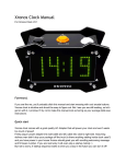
Chipcon
RadioDesk™
Reference
Design and
Protocol
User Manual
Rev. 1.3
Introduction
RadioDesk™ protocol
RadioDesk™ hardware reference
design
RadioDesk™ firmware
Customization
Supported chips
CC2500
Table of contents
1.
2.
3.
4.
Introduction ..................................................................................................................... 4
About this manual ........................................................................................................... 4
Definitions ....................................................................................................................... 4
RadioDesk™ protocol..................................................................................................... 5
4.1
Overview ..................................................................................................................... 5
4.2
Terminology ................................................................................................................ 5
4.3
Physical layer .............................................................................................................. 6
4.4
Frequency hopping ..................................................................................................... 6
4.5
Data flow ..................................................................................................................... 7
4.6
Packet format .............................................................................................................. 8
4.6.1
General packet format ......................................................................................... 8
4.6.2
Beacon payload ................................................................................................... 8
4.6.3
Data payload........................................................................................................ 9
4.6.4
Mouse data ........................................................................................................ 10
4.6.5
Keyboard data.................................................................................................... 10
4.7
IDs and pairing .......................................................................................................... 10
4.8
Power saving............................................................................................................. 11
4.9
Battery life time ......................................................................................................... 13
4.9.1
Optical/laser mouse ........................................................................................... 13
4.9.2
Keyboard............................................................................................................ 15
4.9.3
USB dongle........................................................................................................ 15
5.
The RadioDesk™ reference design hardware ............................................................. 16
5.1
Small-factor USB dongle........................................................................................... 16
5.2
Wireless keyboard..................................................................................................... 22
5.3
Wireless mouse......................................................................................................... 27
6.
The RadioDesk™ reference design firmware............................................................... 34
6.1
Overview ................................................................................................................... 34
6.2
Code structure........................................................................................................... 34
6.3
Code generation and maintenance........................................................................... 35
6.4
MAC functionality ...................................................................................................... 37
6.5
Master ....................................................................................................................... 38
6.6
Slave ......................................................................................................................... 41
6.7
Slave scheduler......................................................................................................... 43
6.8
Adding slave features................................................................................................ 46
6.9
Power management .................................................................................................. 46
7.
Modifications ................................................................................................................. 48
7.1
Suggestions to lower price ........................................................................................ 48
7.2
Suggestions for longer battery life time..................................................................... 48
7.3
Suggestions for advanced functionality .................................................................... 48
7.4
Suggestions for applying RadioDesk™ to other applications ................................... 48
8.
Document history.......................................................................................................... 49
Table of figures
Figure 1. Basic RadioDesk™ frame structure ........................................................................... 5
Figure 2. Typical RadioDesk™ data flow .................................................................................. 7
Figure 3. Basic packet format.................................................................................................... 8
Figure 4 Suggested mouse data ............................................................................................. 10
Figure 5 Suggested keyboard data ......................................................................................... 10
Figure 6. Resynchronisation after sleep.................................................................................. 12
Figure 7. Resynchronisation after channel switch................................................................... 12
Figure 8. Resynchronisation after reset .................................................................................. 12
Figure 9. Optical mouse power mode transitions .................................................................... 14
Figure 10. Example of RadioDesk system with dongle and laser mouse ............................... 16
Figure 11. USB dongle schematic, page 1.............................................................................. 17
Figure 12. USB dongle schematic, page 2.............................................................................. 18
Figure 13. USB dongle schematic, page 3.............................................................................. 19
Figure 14. USB dongle schematic, page 4.............................................................................. 20
Figure 15. Keyboard schematic, page 1.................................................................................. 23
Figure 16. Keyboard schematic, page 2.................................................................................. 24
Figure 17. Keyboard schematic, page 3.................................................................................. 25
Figure 18. Keyboard schematic, page 4.................................................................................. 26
Figure 19. Mouse schematic, page 1 ...................................................................................... 28
Figure 20. Mouse schematic, page 2 ...................................................................................... 29
Figure 21. Mouse schematic, page 3 ...................................................................................... 30
Figure 22. Mouse schematic, page 4 ...................................................................................... 31
Figure 23. Button and sensor board for laser mouse .............................................................. 32
Figure 24. Firmware layers and associated files ..................................................................... 35
Figure 25 - File organisation.................................................................................................... 36
Figure 26. Dongle state diagram ............................................................................................. 38
Figure 27. Slave modes........................................................................................................... 38
Figure 28. Dongle program flow .............................................................................................. 40
Figure 29. Slave states............................................................................................................ 41
Figure 30. Slave program flow................................................................................................. 42
Figure 31. Power management ............................................................................................... 46
1. Introduction
RadioDesk™ is Chipcon’s platform for wireless HID (Human Interface Device) devices. This
platform is based on Chipcon’s SmartRF®04 radio ICs, and includes a complete reference
design as well as an advanced RF adaptive frequency hopping protocol.
The RadioDesk™ reference design is a complete, production ready wireless desktop
(keyboard and mouse) design. Focus is on low cost, a robust RF link in the face of heavy
interference from other 2.4 GHz RF systems and long battery lifetime.
The RadioDesk™ protocol is an advanced adaptive frequency-hopping protocol and designed
specifically for wireless HID use. It is more efficient and optimised for this purpose compared
to other more general-purpose protocols. Interoperability between different implementations
of RadioDesk™ has not been a priority, as this would compromise the main goals.
Implementers are also free to modify RadioDesk™ to suit their specific purposes.
Note that RadioDesk™ is not a one-off project by Chipcon; Chipcon intends to continue to
improve and optimise these materials. Make sure you are kept updated with the latest
developments by subscribing to our Developer’s Newsletter.
This advanced 2.4 GHz solution has many advantages compared to a conventional 27 MHz
design. The most important are the improved range and the possibility of having many
systems operating in a small area.
The RadioDesk™ reference design firmware source code as well as hardware Gerber files
are available free-of-charge, please contact your local Chipcon representative to receive
these files.
2. About this manual
This manual presents both the RadioDesk™ protocol and the RadioDesk™ reference design.
It provides all the technical material needed for an implementer to duplicate and modify both
the hardware and software. It also explains in detail how the design works, and possible ways
of modifying it.
3. Definitions
HID
PTU
CDMA
FDMA
FEC
Human Interface Device – the term used in USB nomenclature
covering keyboard, mice and other user-interface devices
Time Division Multiple Access – a method for supporting multiple
devices where devices coexist by transmitting at different times
Protocol Time Unit – the length of a time slot
Code Division Multiple Access
Frequency Division Multiple Access
Forward Error Correction
CRC
FSK
MSK
HAL
MAC
RSSI
Cyclic Redundancy Check
Frequency Shift Keying
Minimum Shift Keying
Hardware Abstraction Layer
Medium Access
Received Signal Strength Indication
TDMA
RadioDesk™ User Manual
Revision 1.3
Page 4
4. RadioDesk™ protocol
4.1 Overview
The RadioDesk™ protocol is an advanced protocol for wireless HID devices and includes
adaptive frequency hopping. The protocol was based on the following design criteria:
•
•
•
•
Coexistence with existing 2.4 GHz systems
Use of ultra-low-cost MCUs
Long battery life time
Low latency
RadioDesk™ has been designed to be easily customizable to the implementer’s
requirements. It can support a variable number of peripherals, various data formats, both oneway and two-way RF links and so on.
RadioDesk™ is a master-slave protocol. In a standard wireless mouse or keyboard system,
the USB or PS/2 dongle will be the master and the other devices will be slaves. To save
power, the protocol has been designed for asymmetric power consumption. It is assumed that
the master has a plentiful source of power, while the slaves are power-constrained. This holds
true in most HID systems.
RadioDesk™ uses time-division multiplexing (TDMA) to support multiple devices. A big
advantage of the TDMA approach is that it provides infinite attenuation between the various
devices, unlike a CDMA or FDMA approach, where differing signal strengths can cause
problems. A frame is divided into n+2 time slots, where n is the number of slaves in the
system. In the first time slot, the master transmits a beacon. This beacon serves three
purposes; it allows for data transfer from the master to the slaves, inform the slaves of the
network status, and allow the slaves to synchronise their timing to the master.
After the beacon, the slaves transmit data to the master if they have data to report. The last
time slot is used by the master to scan a channel for use in the frequency adaptivity.
Time slot 0
(Beacon)
Time slot 1
(Keyboard)
Time slot 2
(Mouse)
Time slot 3
(Remote
control)
Time slot 4
(Frequency scan)
Time slot 0
(Beacon)
...
Frame
Figure 1. Basic RadioDesk™ frame structure
Figure 1 shows how this looks in a system with three slaves; a keyboard, a mouse and a
remote control. Once a frame is complete, the next frame follows immediately afterwards.
The slaves can power-down at any time, they are not required to respond to the beacon
unless they have data to report.
4.2 Terminology
As described above, the basic protocol period starting with a beacon and ending just before
the next beacon is called a frame. Each frame is sent and transmitted on a new channel in the
frequency hopping sequence.
A frame is divided into time slots. There is sufficient space in a time slot to transmit or receive
a single packet. Each time slot is dedicated to a single unit. The time slots are per definition
one PTU (Protocol Time Unit) long.
RadioDesk™ User Manual
Revision 1.3
Page 5
A packet contains data that is sent from one unit to another. It consists of a preamble, sync
word and payload data followed by a CRC. The packet format is described in more detail later
on.
A channel is a logical number applied to a physical frequency. RadioDesk uses up to 64
channels, numbered from 0 to 63, even though the physical frequencies used for each
channel may vary depending on the implementation.
Active channels are the 4 channels that are active in the frequency-hopping scheme.
4.3 Physical layer
RadioDesk™ is designed to operate in the worldwide, 2.4 GHz license free frequency band,
but could be ported to work at other frequencies. Since the CC1100 is register-compatible
with the CC2500, it is very easy to port RadioDesk™ to work in the US 902-928 MHz
frequency band, for instance. The implementer has to make sure that RadioDesk™ complies
with appropriate regulatory requirements (for instance duty cycle or frequency hopping
requirements).
RadioDesk™ is designed to operate with a RF data rate of 250 kbps. The RadioDesk™
reference design uses the CC2500 transceiver and utilizes MSK as modulation method. It is
easy to modify the system to operate at different data rates. One very simple modification is
to increase the data rate to 500 kbps.
RadioDesk™ can also be implemented on other RF transceivers. For instance, some
implementers may want to utilize an IEEE 802.15.4 compatible radio such as the CC2420.
The data rate is the same, but the number of total channels need to be reduced. Other than
that, the software may be left essentially unchanged.
Parameter
Frequency range
Frequency spacing
Data rate
Modulation
PLL lock time / start time from
IDLE (blanking period)
PTU
Spread spectrum technique
Number of channels used
Allowed range
2401-2464
1
250 (500 if FEC is to be used)
FSK or MSK
<192
Unit
MHz
MHz
kbps
2000
Adaptive frequency hopping
4 active, selected from 64 possibilities
µs
µs
Table 1. Basic physical layer parameters
4.4 Frequency hopping
RadioDesk™ is an adaptive frequency hopping protocol. Both the master and the slaves
change frequency for each frame.
RadioDesk™ uses four active frequencies at any one time. These are selected from a set of
64 possible channels. The master scans through all 64 channels continuously, at a rate of
one channel each frame. If one of the active channels has significantly worse performance
than the best non-active channel, then the master switches out the bad channel with the good
one. To ensure that the active channels are not so close together that a single wide-band
interferer could jam all of them at once, there is a limitation on the channel selection
algorithm.
The frequency hopping is controlled by a 15-bit pseudo-random sequence. This sequence
has a length of 32767 bits. Since 32767 is not divisible by 2, and 2 bits are used to determine
the channel used, the RadioDesk™ hopping sequence will only repeat after 32767 hops have
been made. The pseudo-random sequence can be implemented as a 15-bit shift register with
the appropriate XOR feedback. By setting the shift register to a value, it is possible to select a
RadioDesk™ User Manual
Revision 1.3
Page 6
position in the sequence. This is called the seed by analogy to random number generator
algorithms. Two units can ensure that they are at the same place in the sequence by
comparing the value of the entire shift register. The seed is transmitted in beacon packets so
that slaves can synchronise with the pseudo-random sequence of the master.
The implementer might choose to use a purely sequential switch between the four active
channels. This would make the two seed bytes in the beacon redundant.
4.5 Data flow
The master transmits a beacon packet in the first time slot of each frame. The beacon packet
contains protocol status information and data which the master wants to communicate to the
slaves. In a system where the master needs to transmit more data to the slaves than there is
place for in the beacon packet, there are two possibilities: Either the time slot length can be
extended or an extra time slot can be added for beacon transmission.
When a slave has data to transmit, it listens for a beacon and then transmits a packet in its
dedicated time slot. To listen for beacons is not mandatory for a slave; it is free to go into
power-down mode at any time to save power. In addition, the slaves do not need to transmit a
packet if they do not have data to provide. If a slave transmits data to the master, the master
will use the acknowledge bits in the next beacon to confirm the data transfer. If the
appropriate acknowledge bit is not set, the slave can retransmit the packet in the next frame.
Figure 2 shows a typical RadioDesk™ usage scenario.
No activity
Receive 4
Scan
Beacon 5
Receive 5
Scan
Beacon 6
Receive 6
Scan
Beacon 7
2 PTU
1 PTU
1 PTU
2 PTU
1 PTU
1 PTU
2 PTU
1 PTU
1 PTU
Activity
Dongle
Receive 4
Scan
Beacon 5
Receive 5
Scan
Beacon 6
Receive 6
Scan
Beacon 7
2 PTU
1 PTU
1 PTU
2 PTU
1 PTU
1 PTU
2 PTU
1 PTU
1 PTU
1 PTU
Mouse
Search for
beacon
1 PTU
Transmit 5
Search for
beacon
1 PTU
Keyboard
Search for
beacon
Transmit 5
Transmit 6
Search for
beacon
1 PTU
Search for
beacon
Transmit 6
Search for
beacon
Figure 2. Typical RadioDesk™ data flow
RadioDesk™ User Manual
Revision 1.3
Page 7
4.6
Packet format
4.6.1
General packet format
RadioDesk™ employs a general packet format, but the packet format can be modified to suit
the application if necessary.
Preamble
Sync word
Length
Payload
CRC
32 bits
32 bits
8 bits
max. 12
bytes
16 bits
Figure 3. Basic packet format
The packet starts with a preamble, which is used to settle the receiver chain. Sync word is
then sent to differentiate different systems. This is followed by a length byte which indicates
the length of the payload field (excluding the CRC and the length byte itself). The last part of
the packet is a 16-bit CRC used to check for packet corruption.
4.6.2
Beacon payload
The beacon contains 12 bytes of payload; the meaning of each field is shown in
Table 2 below.
Byte
pos.
0
Name
Network ID
2
Seq/type.
Field
Length
Purpose
16 bits
Unique ID for
each
RadioDesk™
network
7..5
3 bits
Type
packet
4..0
5 bits
POWER
SAVE
7
1 bits
Reserved
MOUSE
bind request
6..2
1
5 bits
1 bits
KEYBOARD
bindrequest
0
1 bits
TYPE
3
4
6
7
Status
Hop
sequence
info
Ack
Bit pos.
16 bits
8 bits
Active
channels
RadioDesk™ User Manual
Comments
of
000=Beacon
Reserved
future use
Enable power
saving
in
slaves
Not used
Indicate that a
mouse
may
bind
Indicate that a
keyboard may
bind
Current
position in hop
sequence
Ack of slave
messages
previous
frame
LSB=slave 0
MSB=slave 7
0: keyboard
1: mouse
Byte
CH1
Byte
CH2
Byte
Revision 1.3
for
pos
7:
pos
8:
pos
9:
Page 8
CH3
Byte pos 10:
CH4
11
Data
RESERVED
FREQ
7..6
5..0
2 bits
6 bits
Reserved
7..0
7 bits
Not used
Active
frequency on
channel
Applicationdependent,
can be used
to send data
from master to
slaves (Capslock
status
etc)
Table 2. Beacon payload
4.6.3
Data payload
Byte
pos.
0
Name
ID
3
TYPE
4
Field
Length
Purpose
16 bits
Unique ID for
each
RadioDesk™
network
TYPE
7..5
3 bits
Type of packet
RESYNC
4
1 bit
Sequence
number
3..0
4 bits
7..0
1 bit
Set if device is
waking
up.
Cleared by first
ACK
from
dongle.
Control
retransmissions
Paired bit
6..0
7 bits
Status
4
5
Bit
pos.
Data
max.
bytes
Implementation
dependent
6
Comments
001=Mouse
010=Keyboard
Set when a
slave
has
been paired
May be used
to report, say,
motion sensor
status
or
number
of
characters in
the keyboard
buffer
Used to report
data
from
slaves
to
master (mouse
movements,
keyboard hits
etc.)
Table 3. Data payload
RadioDesk™ User Manual
Revision 1.3
Page 9
4.6.4
Mouse data
The optical sensor typically provides two 8-bit delta values for X and Y movement. This is also
what is required for boot functionality by the PC BIOS.
Button status
Delta X
Delta Y
Scroll wheel
Additional data
8 bits
8 bits
8 bits
8 bits
max 8
bits
Figure 4 Suggested mouse data
In the additional data field it’s possible to send data such as battery status, scroll wheel data
and so on. When buttons are pressed, the mouse should send data packets in each frame.
The master should implement a keep-alive function, so that if no data is received from the
mouse for several frames, the master should report to the PC that all buttons are released.
This prevents stuck buttons if the radio link goes down.
4.6.5
Keyboard data
Boot functionality demanded by PC BIOS consists of the first byte of modifier keys, then up to
6 key codes.
Modifier keys
Key 1
Key 2
Key 3
Key 4
8 bits
8 bits
8 bits
8 bits
8 bits
Figure 5 Suggested keyboard data
If LED indicators for caps-lock, num-lock and so on are included, data can be sent in the
single data byte available in the beacon packet.
4.7 IDs and pairing
The RadioDesk™ reference design uses 16-bit IDs, but may easily be amended to use 24
bits. This serial number is embedded into the OTP MCU in the master device. In order to
minimise the chance of collisions, a random ID should be selected before starting a
manufacturing batch, and then the IDs should be incremented sequentially for each set in the
batch. Randomizing the start number is wise; otherwise the first production units for each
manufacturer would start at 0, and be likely to be equal to equipment from other
manufacturers.
The likelihood of two different sets having the same ID can be found from the so-called
Birthday Theorem in statistics (so-called as the archetypical use is to find out how likely it is
that two persons in a group share the same birthday):
P(collision) <
q(q − 1)
2N
Equation 1. Birthday theorem
q is the number of units and N is the number of possible IDs.
RadioDesk™ User Manual
Revision 1.3
Page 10
Another approximation is that approximately one collision will occur if you have N units
within range. This turns out to be 4048 units for a 24-bit ID, or 256 units for a 16-bit ID.
The following table gives the upper bound on the collision probability for 16-bit and 24-bit IDs
(assuming a random distribution):
Number of
within range
1
2
4
8
16
32
64
128
256
512
1024
units
Upper bound on probability of
collision (24-bit ID)
0
5,96046E-08
3,57628E-07
1,66893E-06
7,15256E-06
2,95639E-05
0,000120163
0,000484467
0,001945496
0,007797241
0,031219482
Upper bound on probability of
collision (16-bit ID)
0
1,52588E-05
9,15527E-05
0,000427246
0,001831055
0,007568359
0,030761719
0,124023438
0,498046875
1
1
Table 4. Probability of ID collisions
As can be seen, the probability of a network collision is remote when using a 24-bit ID as long
as the number of units within range is below several hundreds. So many units will never be
within range of each other, even in a very crowded office environment. Problems due to
network collisions will be less likely than problems due to hardware failures in the field. Using
a 16-bit ID is only recommended where only a few units will ever be within range of each
other.
In some cases such a system is not practical (for example when using ROM-based MCUs),
and another form of pairing should be used. The conventional way of doing pairing is having a
button on each of the units, and then require the user the press these buttons to pair the
devices (the likelihood of another unit close-by being in pairing mode at the same time is very
remote). This works well, but requires the user to perform this procedure every time the
batteries are changed. The master contains a fixed ID, which the slaves bond to. This is done
because the master will lose power every time the PC is switched off, while the slaves can
rely on battery power.
RadioDesk™ implements a simple pairing scheme where the master has a fixed ID and the
slaves attempt to bind to the dongle when they are reset. The slave will attach to the first
encountered master sending a beacon that it receives with a signal strength above a certain
threshold.
4.8 Power saving
RadioDesk™ allows the slaves to power-down at any time in order to save as much power as
possible. When a slave wakes up, it first checks the channels that were active when it
powered down. If it does not find the beacon in a predefined number of tries, it goes into
search mode and searches all the 64 possible channels.
When searching, the slave hops between random frequencies. If no frequency changes have
occurred since the slave went to sleep, Figure 6 shows the probability of finding the beacon
after a certain number of frames.
If a single frequency has been changed, then the probability distribution in Figure 7 is correct.
If all four frequencies have been changed, or after a reset, then the probability distribution
follows the curve in Figure 8.
RadioDesk™ User Manual
Revision 1.3
Page 11
Probability of synchronisation
Resync after sleep
1
0,9
0,8
0,7
0,6
0,5
0,4
0,3
0,2
0,1
0
0
2
4
6
8
10
12
14
16
12
14
16
Num ber of fram es
Figure 6. Resynchronisation after sleep
Probability of synchronisation
Resync after channel switch
1
0,9
0,8
0,7
0,6
0,5
0,4
0,3
0,2
0,1
0
0
2
4
6
8
10
Num ber of fram es
Figure 7. Resynchronisation after channel switch
Probability of synchronisation
Resync after reset condition
1
0,9
0,8
0,7
0,6
0,5
0,4
0,3
0,2
0,1
0
0
50
100
150
200
Num ber of fram es
Figure 8. Resynchronisation after reset
RadioDesk™ User Manual
Revision 1.3
Page 12
Typical HID devices will be used erratically, with periods of use being separated by long
periods of inactivity. Studies show that the user can tolerate somewhat longer latency for the
first event after a period of inactivity. The device should therefore look at the time since the
last event, and switch into a low-power mode after a certain period of inactivity. This approach
has been adopted by the manufacturers of movement sensors and is used in optical mice.
4.9 Battery life time
Battery lifetime is one of the key parameters for a wireless HID solution. In order to estimate
this, it is necessary to know the characteristics of the battery that will be used as well as
knowing how the device will be used.
In many aspects, alkaline AA or AAA cells are ideal for powering a HID device. They are
inexpensive and available just about everywhere. Good quality AA cells have a rated capacity
of 2850 mAh, while AAA cells are rated to 1250 mAh. End-of-life voltage is usually given to be
0.9 V.
Depending on the MCU and other circuitry used, several voltage regulation schemes are
possible:
1. The unit may be powered directly from the batteries. The CC2500/CC2550 radio
supports a voltage supply range of 1.8 – 3.6 V. This fits very well with the 1.8 – 3.2 V
range of two serially connected alkaline cells. If the other circuitry in the unit can also
operate with this input voltage range, then this is the preferred option, as it provides
the lowest cost and utilizes the battery capacity to the best extent. It is possible to use
direct powering even if the minimum supply voltage of the MCU or another critical
component is more than 1.8V, but then the battery life time will be reduced
accordingly.
2. The unit is powered from 4 alkaline cells, using a 3 V or 3.3 V linear regulator. This
will allow the unit to utilize the whole battery capacity, but 4 batteries are physically
bulky. This can be a good solution for a wireless keyboard, as space is generally not
a problem, but is not practical for a wireless mouse because of size and bulk. Some
capacity is wasted in the voltage regulator.
3. The unit is powered from 1 or 2 alkaline cells, using a switch-mode boost converter.
This may be required if other circuitry requires a 3.3V supply (for example the optical
sensor in a wireless mouse), and size constraints forbid the use of more than 2 cells.
This increases cost (~ USD $0.30 in large quantities) and some battery capacity is
wasted because the voltage regulator efficiency is never 100%, but it does work down
to the minimum battery voltage and enables very small designs using a single cell.
In order to estimate battery lifetime, the easiest technique is to calculate an average current
draw, and then divide the capacity by the average current to find the battery life time in hours.
Please note that battery capacity will be slightly lower when a varying current is drawn than if
the current was constant.
To calculate an average current, it is necessary to calculate the length of time spent in various
states and how much current is drawn in each state.
In order to simplify checking different scenarios for power consumption, Chipcon has made
Excel spreadsheets that perform the appropriate calculations. These spreadsheets are
enclosed in a .ZIP file together with this document.
4.9.1
Optical/laser mouse
An optical or laser mouse is typically the most power-intensive user-interface device because
of the current consumption of the sensor. A LED is also used to provide light for the sensor.
The mouse will therefore usually be the most power-constrained device.
Agilent has provided the following usage profile for a typical business user (home users
usually use their systems much less, and will get correspondingly longer battery life times):
RadioDesk™ User Manual
Revision 1.3
Page 13
1.4% of active usage (with minimum latency)
4.0% of inactive usage (with higher latency on wake-up)
94.6% power-down (with the highest latency on wake-up)
The mouse supports four different power modes:
• Active, where the optical sensor is turned on all the time, the scroll wheel is active,
the MCU is active and the radio is receiving, listening to beacons and transmitting
position data to the master. If no activity is detected for 800 milliseconds, the mouse
goes into semi-active mode.
• Semi-active, where the optical sensor is being duty-cycled to save power, the scroll
wheel is not active, the MCU is active and the radio is listening to beacons. If activity
is detected, the mouse goes to active mode. If no activity is detected for 60 seconds
while in semi-active mode, the mouse goes into sleep mode.
• Sleep, where the optical sensor is being duty-cycled at a low rate, the scroll wheel is
not active, the MCU is in sleep most of the time and the radio polls for beacons at
regular intervals. If activity is detected, the mouse goes into active mode. If beacons
have not been detected for 400 milliseconds the mouse enters deep sleep mode.
• When no beacons have been found for 400 milliseconds, then the PC is either shut
off, out of range or in suspend mode. The mouse then enters deep sleep. In this
mode, the optical sensor is shut entirely off, the scroll wheel is shut off, the MCU is in
power down mode and the radio shut off. If the user presses a mouse button, the
mouse first tries a sends wake-up messages and tries to wake the PC from suspend
mode. If it is not successful, the mouse gives up and resumes deep sleep.
Figure 9 shows what events trigger transitions between the different power modes.
Movement or button press
Active
Movement or button press
Button press
Semi-active
Sleep
Deep sleep
No beacons received for z seconds
No movement or button presses for y seconds
No movement or button presses for x seconds
Figure 9. Optical mouse power mode transitions
In active mode, the MCU is active, the scroll wheel is active, the optical sensor is continually
on and the radio is listening for beacons and transmitting data back to the master. All parts of
the mouse except the radio are drawing maximum current the whole time. The radio is in RX
mode for one time slot (1/4th of the total 8 ms frame duration for a mouse/keyboard combo),
and in TX mode for the time it takes to send one packet (assuming a 20-byte packet, this is
0.64 ms). The radio will be in IDLE (synthesizer running) when it is not transmitting or
receiving.
In semi-active mode, the MCU is active, the scroll wheel is turned off, the optical sensor is
being duty-cycled and the radio is listening to beacon packets, being in IDLE for the rest of
the time.
In sleep mode, the MCU is waking up at intervals, the scroll wheel is turned off, the optical
sensor is being duty-cycled and the radio is being woken up periodically.
The radio wakes up every 5 seconds to check for beacons and frequency changes. When it
wakes up, it needs to resynchronise. 90% of the time, this will take less than 8 frames.
RadioDesk™ User Manual
Revision 1.3
Page 14
In deep-sleep, the slave is completely off and the unit has to be woken up by a button press.
It will then scan for beacon, and afterwards try to wake up the master if no beacon is found.
Please see the Excel spreadsheet for detailed calculations on power consumption.
4.9.2
Keyboard
The keyboard is usually less power-intensive than the mouse, because the system need only
wake up when a key press is detected. Again, the usage pattern has a great deal of influence
on the battery life time.
Since the CC2500 supports a voltage supply range of 1.8-3.6V, and the MCU used supports
a voltage supply down to 2.2V, it is attractive to run all the circuitry directly from the batteries
to save cost. It is estimated that the system can utilise 80% of the total battery life time if it
cuts off at 2.2V.
In heavy business usage, the keyboard might be used 4 hours a day for 5 days a week.
During this time, keyboard usage is irregular, but the total amount of time that the radio is
active will be 10% of the time (the keyboard goes from active to sleep after 1 seconds of nonactivity). This gives a total active time of around 20 minutes per day.
In active mode, the power consumption of the MCU is 0.7 mA, while the radio average current
is 6.8 mA (same calculations as for the optical mouse in active mode). This gives a total
average current of 7.5 mA. 20 minutes per day is equal to a 1.25% duty cycle. This gives an
average current of around 0.1 mA. Sleep-mode current is approximately the same, assuming
that the radio and MCU are active for 64 ms every 5 seconds to maintain information about
frequency changes and so on. This gives a total average current consumption of 0.2 mA.
Please see the Excel spreadsheet for detailed calculations.
4.9.3
USB dongle
The USB standard mandates that any USB device that can wake up the computer should not
draw more than 0.5 mA when the PC is in the low-power suspend state. To achieve this, the
RF transceiver in the dongle must be power cycled (usually it is on all the time as in active
mode the USB current limitation is 100 mA).
Assuming the USB MCU and mandatory USB pull-up resistors draw 0.25 mA, this leaves 0.25
mA or 250 uA for the radio. Since the CC2500 power-down current with wake-on-radio
enabled is only 1.5 uA, this can be ignored in the calculation. Taking the worst-case CC2500
current consumption in RX of 15.6 mA into account, the duty cycle must be lower than
0.25/15.6, or 1.6%. This means that the CC2500 can be active for 16 ms every second. For
the specific purpose of waking up a PC from suspend mode, it is suggested that a singlechannel approach is taken. The reason for this is that long latency is usually acceptable, it is
not a problem in the wake-up scenario, since wake-up itself takes many seconds. Secondly,
most interferers are only transient in nature, so a device jamming the wake-up frequency for
several seconds is not likely.
Wake-up functionality would not be possible at all using a low-cost MCU if it were not for the
CC2500 wake-on-radio function, which enables the MCU to stay in the lowest-power state
while the radio scans for activity. It is recommended that the wake-up channel be selected
based on the network ID.
If wakeup is used, the keyboard and mouse will be programmed to transmit a long (several
second) series of wake-up messages on the wake-up channel when user action occurs and
the mouse and keyboard cannot find a beacon.
RadioDesk™ User Manual
Revision 1.3
Page 15
5. The RadioDesk™ reference design hardware
The RadioDesk™ reference design consists of a wireless mouse, wireless keyboard and a
small form-factor USB dongle. The hardware has been designed with very low-cost
components and with large-scale manufacturability in mind.
HT82K68E
(also
connects to
scroll wheel,
buttons etc)
NCs
Csn
Sclk
Si
So
Csn
Sclk
Si
CC2500
CC2500
So
gdo0
gdo0
gdo2
gdo2
HT82K96E
with USB
Motion
ADNS 6030
Dongle
Mouse
Figure 10. Example of RadioDesk system with dongle and laser mouse (Note: gdo0 is
not used in RadioDesk firmware, but may be used in the future)
5.1 Small-factor USB dongle
The USB dongle has been designed to exhibit a minimum form factor. To achieve this, a 4layer PCB has been used as well as a chip antenna solution.
A HTK96E low-speed USB MCU from Holtek Semiconductor was selected for the dongle.
This MCU is powered directly from USB bus power. A 12 MHz crystal is used as clock source.
The USB MCU communicates with the CC2500 transceiver using a bit-banged SPI serial
interface, and reports data received from the keyboard and the mouse to the PC. A LED is
included to show the link status.
The CC2500 2.4 GHz RF transceiver uses a balun circuit to interface with the single-ended
chip antenna. The chip antenna is an advanced design from Fractus, which provides excellent
antenna performance even though the size is very small. The CC2500 is powered from a
3.3V linear regulator.
The RF circuitry, the antenna and the voltage regulator are placed on the top side of the PCB,
while the USB MCU is mounted on the bottom side. Actually, these directions are reversed
with regards to the usual rotation of the USB plug, so the LED is mounted on the same side
as the MCU as to be visible when plugged into a horizontally oriented USB socket. When
laying out your own PCB, it is very important to copy the PCB layout of the RF section
exactly. Layer 2 is used for a ground plane, while layer 3 is used to route power.
RadioDesk™ User Manual
Revision 1.3
Page 16
If price is more important than physical size, then it is possible to use copy the RF section and
PCB antenna from the keyboard or mouse and connect this to the USB MCU and other
circuitry in the dongle design. In this case, a 2-layer PCB can be used. The RF layout should
be copied exactly from the keyboard or mouse, paying attention to ground planes as well. The
usual alternative to a small USB dongle is to make a “hockey puck” formed device that
connects to the PC via a USB cable.
Figure 11. USB dongle schematic, page 1
RadioDesk™ User Manual
Revision 1.3
Page 17
Figure 12. USB dongle schematic, page 2
RadioDesk™ User Manual
Revision 1.3
Page 18
Figure 13. USB dongle schematic, page 3
RadioDesk™ User Manual
Revision 1.3
Page 19
Figure 14. USB dongle schematic, page 4
RadioDesk™ User Manual
Revision 1.3
Page 20
Reference
A1
C1
C2
C3
C4
C5
C6
C7
C8
C9
C10
C11
C12
C13
C41
C51
C81
C91
C101
C111
C121
C122
C123
C124
C131
C132
C141
C151
C181
D3
L121
Value/part number
Compact Reach Xtend
100 nF, X5R, 10%
100 nF, X5R, 10%
10 µF, X5R, 15%
2.2 µF, X5R, 10%
47 pF, NP0, 5%
100 nF, X5R, 10%
100 nF, X5R, 10%
100 nF, X5R, 10%
47 pF, NP0, 5%
47 pF, NP0, 5%
10 nF, X7R, 10%
100 nF, X5R, 10%
47 pF, NP0, 5%
100 nF, X5R, 10%
100 nF, X5R, 10%
27 pF, NP0, 5%
220 pF, X7R, 10%
27 pF, NP0, 5%
100 nF, X5R, 10%
100 pF, NP0, 5%
1.0 pF, NP0, ± 0.25 pF
1.8 pF, NP0, ± 0.25 pF
1.5 pF, NP0, ± 0.25 pF
100 pF, NP0, 5%
1.0 pF, NP0, ± 0.25 pF
100 nF, X5R, 10%
220 pF, X7R, 10%
220 pF, X7R, 10%
CL150YCD
1.2 nH, ± 0.3 nH
L122
L131
P1
1.2 nH, ± 0.3 nH
1.2 nH, ± 0.3 nH
CONN10_MALE
P2
P3
CONN10_MALE
R1
R2
R3
R4
R6
R7
R8
R9
R10
R102
R104
R106
R171
33 Ω, 2%
100 kΩ, 2%
10 kΩ, 2%
100 kΩ, 2%
4.7 Ω, 5%
33 Ω, 2%
33 Ω, 2%
1.5 kΩ, 2%
4.7 Ω, 5%
10 kΩ, 2%
10 kΩ, 2%
10 kΩ, 2%
56 kΩ, 1%
RadioDesk™ User Manual
Description
Chip antenna
Capacitor 0402
Capacitor 0402
Capacitor 0805
Capacitor 0603
Capacitor 0402
Capacitor 0402
Capacitor 0402
Capacitor 0402
Capacitor 0402
Capacitor 0402
Capacitor 0402
Capacitor 0402
Capacitor 0402
Capacitor 0402
Capacitor 0402
Capacitor 0402
Capacitor 0402
Capacitor 0402
Capacitor 0402
Capacitor 0402
Capacitor 0402
Capacitor 0402
Capacitor 0402
Capacitor 0402
Capacitor 0402
Capacitor 0402
Capacitor 0402
Capacitor 0402
LED, yellow, SMD
Multi-layer
inductor
0402
Inductor 0402
Inductor 0402
Connector,
0.9mm
pin, male (only for
test)
USB plug type A
connector
Connector,
0.9mm
pin, male (only for
test)
Resistor 0402
Resistor 0402
Resistor 0402
Resistor 0402
Resistor 0603
Resistor 0402
Resistor 0402
Resistor 0402
Resistor 0603
Resistor 0402
Resistor 0402
Resistor 0402
Resistor 0402
Revision 1.3
Manufacturer
Fractus
Page 21
R205
U1
270 Ω, 2%
CC2500
U2
HT82K96E-SOP20
U3
X1
NJM2871BF03
X_26.000/20/20/10/16
X2
X_12.000/50/50/10/12
Resistor 0402
CC2500 2.4 GHz RF
transceiver
USB MCU
3.0V LDO regulator
26.000 MHz crystal,
20/20 ppm tolerance,
HC-49/NX5032-SMD
12.000 MHz crystal,
50/50 ppm tolerance,
HC-49-SMD
Chipcon
Holtek
Semiconductor
New Japan Radio
Table 5. USB dongle bill of materials
5.2 Wireless keyboard
The wireless keyboard electronics consists of a small PCB which connects to the main
keyboard matrix using carbon contacts. All the electronics are powered directly from the
batteries. A HT82K68E serves as the system MCU, reading the keyboard matrix and running
the radio protocol.
The CC2500 2.4 GHz RF transceiver uses a novel differential PCB antenna. This antenna
has been designed to match the CC2500 RF I/O differential impedance, avoiding the need for
any matching components or balun circuit. This ensures an absolute minimum number of
external components, the CC2500 only requiring a single biasing resistor, a 26 MHz crystal,
two crystal loading capacitors as well as decoupling capacitors.
Three LEDs have been included to indicate caps lock, num lock and scroll lock status. These
may be illuminated only when the user types on the keyboard in order to save power, or even
replaced with a custom LCD display (the LEDs are not implemented in RadioDesk firmware
because it would require drilling holes in the keyboard chassis to make them visible).
The keyboard design does not support extended functionality like a scroll wheel and
additional keys, but this can very easily be added.
RadioDesk™ User Manual
Revision 1.3
Page 22
Figure 15. Keyboard schematic, page 1
RadioDesk™ User Manual
Revision 1.3
Page 23
Figure 16. Keyboard schematic, page 2
RadioDesk™ User Manual
Revision 1.3
Page 24
Figure 17. Keyboard schematic, page 3
RadioDesk™ User Manual
Revision 1.3
Page 25
Figure 18. Keyboard schematic, page 4
RadioDesk™ User Manual
Revision 1.3
Page 26
Reference
C2
C3
C5
C6
C8
C41
C51
C81
C91
C101
C111
C141
C151
C181
D1
D3
D4
D5
L1
P1
P3
R1
R2
R3
R6
R171
TESTCON
U1
U5
X1
Value/part number
27 pF, NP0, 5%
27 pF, NP0, 5%
10 µF, X7R, 20%
100 nF, X5R, 10%
100 nF, X5R, 10%
100 nF, X5R, 10%
100 nF, X5R, 10%
27 pF, NP0, 5%
220 pF, X7R, 10%
27 pF, NP0, 5%
220 pF, X7R, 10%
220 pF, X7R, 10%
220 pF, X7R, 10%
220 pF, X7R, 10%
CL150GCD
CL150URCD
CL150YCD
20BQ030
BLM11A102S
PINROW_2
CON3
100 kΩ, 2%
0Ω
0Ω
0Ω
59 kΩ, 1%
PINROW_2X5
CC2500
HT82K68E-SSOP48
X_26.000/20/20/10/16
X3
KR600MLWB
Description
Capacitor 0402
Capacitor 0402
Capacitor 1206
Capacitor 0402
Capacitor 0402
Capacitor 0402
Capacitor 0402
Capacitor 0402
Capacitor 0402
Capacitor 0402
Capacitor 0402
Capacitor 0402
Capacitor 0402
Capacitor 0402
LED, green, SMD
LED, red, SMD
LED, yellow, SMD
Schottkey diode
EMI filter bead
Pinrow, 2
Connector, 0.9 mm pin
Resistor 0402
Resistor 0603
Resistor 0603
Resistor 0603
Resistor 0402
Pinrow, 2x5 (for test)
2.4 GHz RF transceiver
Keyboard MCU, SSOP48
26.000 MHz crystal, 20/20
ppm
tolerance,
HC49/NX5032-SMD
6MHz resonator
Manufacturer
Murata
Chipcon
Holtek
Kingstate
Table 6. Keyboard bill of materials
5.3 Wireless mouse
The wireless mouse is implemented on two PCBs. The lower PCB includes the micro
switches for the buttons, scroll wheel and optical sensor, while the upper PCB contains the
rest of the electronics.
The electronics are powered from a TPS61078 switch-mode regulator from Texas
Instruments. The reason for this is that the Agilent ADNS-6030 laser sensor needs a supply
voltage between 3.0 and 3.6 V.
The same antenna and RF solution is used in the keyboard and the mouse.
The Z-wheel or scroll-wheel is of an optical type where a LED shines through the wheel itself,
presenting a quadrature signal that is detected by two photo-transistors. The mouse buttons
are implemented using standard micro-switches.
RadioDesk™ User Manual
Revision 1.3
Page 27
Figure 19. Mouse schematic, page 1
RadioDesk™ User Manual
Revision 1.3
Page 28
Figure 20. Mouse schematic, page 2
RadioDesk™ User Manual
Revision 1.3
Page 29
Figure 21. Mouse schematic, page 3
RadioDesk™ User Manual
Revision 1.3
Page 30
Figure 22. Mouse schematic, page 4
RadioDesk™ User Manual
Revision 1.3
Page 31
Figure 23. Button and sensor board for laser mouse
RadioDesk™ User Manual
Revision 1.3
Page 32
Reference
C1
C3
C5
C7
C8
C9
C10
C20
C21
C41
C51
C81
C91
C101
C111
C141
C151
C181
D1
JP1MALE
JP2MALE
L1
L2
P1
P2
P3
R1
R2
R3
R4
R5
R6
R7
R8
R171
U1
U2
U4
Value/part number
10 µF, X7R, 20%
27 pF, NP0, 5%
27 pF, NP0, 5%
100 nF, X5R, 10%
100 nF, X5R, 10%
4.7 µF, X5R, 10%
4.7 µF, X5R, 10%
4.7 µF, X5R, 10%
4.7 µF, X5R, 10%
100 nF, X5R, 10%
100 nF, X5R, 10%
27 pF, NP0, 5%
220 pF, X7R, 10%
27 pF, NP0, 5%
220 pF, X7R, 10%
220 pF, X7R, 10%
220 pF, X7R, 10%
220 pF, X7R, 10%
20BQ030
PINROW_2X4
PINROW_2X4
MSS4020-472MX
BLM11A102S
PINROW_2X5
PINROW_2X5
100 kΩ, 2%
10 kΩ, 2%
82 Ω, 2%
10 kΩ, 2%
10 kΩ, 2%
1 MΩ, 2%
180 kΩ, 2%
10 kΩ, 2%
56 kΩ, 1%
CC2500
HT82K68E-SOP20
TPS61070
X1
X_26.000/20/20/10/16
X2
KR600MLWB
Description
Capacitor 1206
Capacitor 0402
Capacitor 0402
Capacitor 0402
Capacitor 0402
Capacitor 0603
Capacitor 0603
Capacitor 0603
Capacitor 0603
Capacitor 0402
Capacitor 0402
Capacitor 0402
Capacitor 0402
Capacitor 0402
Capacitor 0402
Capacitor 0402
Capacitor 0402
Capacitor 0402
Schottkey diode, 2A
Pinrow, 2x4
Pinrow, 2x4
Power Inductor, 4,7uH
EMI filter bead
Battery connector
Pinrow, 2x5
Pinrow, 2x5
Resistor 0402
Resistor 0402
Resistor 0603
Resistor 0402
Resistor 0402
Resistor 0402
Resistor 0402
Resistor 0402
Resistor 0402
2.4 GHz RF transceiver
Keyboard MCU, SOP20
Synchronous boost switch
26.000 MHz Crystal, 20/20
ppm
tolerance,
HC49/NX5032-SMD
6MHz resonator
Manufacturer
Coilcraft
Murata
Chipcon
Holtek
Texas
Instruments
Kingstate
Table 7. Mouse bill of materials
RadioDesk™ User Manual
Revision 1.3
Page 33
6. The RadioDesk™ reference design firmware
6.1 Overview
The RadioDesk™ reference design firmware runs on the Holtek MCUs used in the mouse,
the keyboard and the dongle. The firmware, except the USB-related code and the SPIinterface to the RF chip, is written in C. The firmware is designed with MCU portability in
mind. Porting to a different controller would only involve changing the HAL and the
aforementioned parts written in assembly.
Note that no software is needed on the PC side; the USB dongle firmware is written to fulfil
the USB HID requirements, so the keyboard and mouse will work with any operating system
that supports USB Human Interface Devices (HID).
The RadioDesk™ protocol uses adaptive frequency hopping on four active channels picked
from 64 possible. The system is always hopping on four channels and a channel is replaced if
the packet loss count exceeds a programmed threshold. For instance, a channel will be
replaced if jammed by a WLAN system.
6.2
Code structure
The RadioDesk™ firmware is divided into four distinct layers, interfacing each other through a
set of functions, macros and definitions. All files, functions and macros have prefixes that
clearly indicate which layer they belong to. The exception is the application layer where no
prefixes are used.
Layer
HAL
RF (PHY)
MAC
APP
Description
Defines the interface between the MCU and the RF chip, sensors and
other IO devices. It also defines the internal registers of the MCU.
Defines the properties of the RF communication link. This is typically
settings like data rate, modulation formats etc. The RF layer is used by the
MAC to establish a link between the master and the slaves.
Defines how the RadioDesk devices communicate across the RF link.
Includes addressing, timing, frequency agility, pairing and retransmission.
The RF chip handles some of the MAC functionality; address filtering
being an example of this
Slaves: Reads data from mouse and keyboard and uses the MAC to
communicate across the RF link.
Master: transfers data between the RF link and the USB interface.
Table 8. Firmware layers
RadioDesk™ User Manual
Revision 1.3
Page 34
MASTER
COMMON
dongle.h
dongle.c
init.c
main.c
APPLICATION
LAYER
common.h
holtek.h
SLAVE
init.c
slave.c
powermanager.c
scheduler.h
scheduler.h
MAC LAYER
mac_scheduler.c
mac_freqhop.c
mac_dongle.c
mac_wor.c
mac_config.h
mac_radiodesk.c
mac_slave.c
mac_resync.c
mac_wakeup.c
mac_pairing.h
mac_mouse.c
mac_keyboard.c
PHYSICAL LAYER
rf_lib.h
rf_lib.c
rf_config.c
HARDWARE
ABSTRACTION
LIBRARY
hal_dongle.h
hal_ioport.c
hal_timer.c
hal_spi.asm
USB software
hal_timer.c
buffer.c
hal_spi.h
hal_nextchannel.c
hal_keyboard.h
hal_keyboardscan.c
hal_ioport.c
hal_spi.asm
hal_mouse.h
hal_zwheel.h
hal_ioport.c
hal_spi.asm
Figure 24. Firmware layers and associated files
6.3
Code generation and maintenance
The RadioDesk™ firmware is delivered as a zip-file. The file contains the code, the
documentation and a list of files and functions in the system. This list (inventory.html) contains
details on where the files and functions are located as well as a short description of each files
contents.
The firmware is built using the HT-IDE3000 development suite from Holtek, which is available
from the Holtek WEB site (www.holtek.com). Please contact Holtek for emulator hardware
(HT-ICE and interface boards).
It is recommended to unpack the code to the folder C:\Radiodesk in order to build directly
from the delivery. Otherwise the HT-IDE3000 project files must be reassembled.
RadioDesk™ firmware and documentation is delivered together in a ZIP-file.
RadioDesk™ User Manual
Revision 1.3
Page 35
The directory structure is shown in Figure 25. C:\RadioDesk is the root.
Figure 25. File organisation
RadioDesk™ User Manual
Revision 1.3
Page 36
The HT-IDE300 project files are located as shown below:
•
•
•
./src/applications/dongle/ht82k96e/rd_dongle.prj
./src/applications/keyboard/ht82k68e/rd_keyboard.prj
./src/applications/lasermouse/ht82k68e/rd_lasermouse.prj
The folder msdev contains Microsoft Visual Studio Project files for the source code. Note that
the code cannot be built using Visual Studio. It is merely there to aid source code navigation.,
and other code organisers like Ultra Edit or Code Warrior may equally well be used.
Basic configuration parameters are found in include/radiodesk/mac_config.h.
//---------------------------------------------------------------------------------// Network ID (range 0x0000 to 0x7FFF)
#define NETWORK_ID
0x3008
//---------------------------------------------------------------------------------// Units to include
#define INCLUDE_KEYBOARD
#define INCLUDE_MOUSE
#define NUM_DEVICES
2
The main configurable parameter, NETWORK_ID, must be unique for each dongle in a
production batch. The “Units to include” is important for implementers who require a system
with only one slave. Uncomment the redundant slave and set NUM_DEVICES to 1.
Basic RF parameters are found in mac_config.h.
//---------------------------------------------------------------------------------// Data rate programming
//#define RF_500KBPS_MSK
#define RF_250KBPS_MSK
//#define FEC_ENABLE
//---------------------------------------------------------------------------------// Output power (values defined in rf_lib.h)
#define OUTPUT_POWER
OUTPUT_M1_DBM // -1 DBm
RadioDesk™ supports 500-kBit/sec data rate in addition to the default 250 kbps. At 500 kbps
the timing allows FEC to be used. The output power is also set in this file.
6.4
MAC functionality
The core of RadioDesk™ is implemented in the MAC layer. Timing properties, device access
and frequency agility are all managed here. The MAC is the interface between the
applications at both ends of the link; it uses the RF (PHY) layer and the CC2500 to establish a
connection over the air.
Timing (synchronisation) is based on the beacon message, transmitted at the start of each
frame. The slaves synchronise their clock on detection of the sync word of the beacon. The
only other synchronised activity in the slave is the transmission of data back to the master.
RadioDesk™ User Manual
Revision 1.3
Page 37
Data collection, power management and buffering of data are carried out independently of the
synchronised activities.
Device access is based on the network identifier. Every set of RadioDesk units needs a
unique ID to allow identification and to avoid interference. The network ID (serial number) is
an integral part of the message in both directions. RadioDesk uses address filtering to reject
messages from neighbouring RadioDesk networks.
Pairing provides flexibility when combining master and slave units. When powered up, the
slaves have no ID and address filtering is disabled. All beacon messages are received but
only the first beacon with a sufficiently high signal strength is considered for pairing. If the
beacon contents indicate that the master is not paired to any device of this type, the slave will
respond and the master subsequently accept the binding request. At this point the slave
enables address filtering and beacons from other networks are ignored.
The Frequency agility scheme of RadioDesk is based partly on packet loss, partly on noise
measurements. The decision to replace a channel is entirely based on packet loss statistics.
6.5
Master
The USB dongle is the master device of RadioDesk and responsible for synchronisation,
frequency selection and data transport. It stays one PTU in each time slot, and the slaves use
beacon reception to synchronise with their master. The four states (time slots) are shown in
Figure 26. Each state corresponds to one PTU or frame slot. The dongles main responsibility
is to transport data from the connected devices to the host computer over USB in a manner,
which is transparent to the driver.
state
BEACON_SLOT
state
KEYBOARD_SLOT
state
MOUSE_SLOT
state
FREQHOP_SLOT
- send beacon to slaves
when not in suspend
mode
-receive keyboard packet
-receive mouse packet
-scan RSSI on one channel
-flag bad active channels for
frequency change if required
-hop to next active channel
Figure 26. Dongle state diagram
In addition to keeping track of time, the master controls and initiates frequency changes on
the active channels. The dongle executes a frequency change if the following criteria are met
with respect to the state of the slaves:
1. The dongle has detected packet loss on a channel.
2. All slaves who are in AQUIRE mode have acknowledged the previous frequency
change.
Slave modes are shown in Figure 27.
no data packet received
last frame
slave mode ACTIVE
-dongle is currently receiving
datapackets from slave.
no data packet received in the last 5 seconds
slave mode AQUIRE
-dongle has not received
data recently from slave and
assumes that a new
datapacket will arrive soon.
slave mode INACTIVE
-dongle does not take the
slave into account as it has
been absent for too long.
datapacket reiceved
from slave
Figure 27. Slave modes
RadioDesk™ User Manual
Revision 1.3
Page 38
In a normal operating environment, at least one slave will be in AQUIRE mode at any given
time. As a result, the dongle has to wait until each slave has been in either ACTIVE mode or
INACTIVE mode before executing two frequency changes successively.
Replacement of an active channel is carried out if and only if all of the conditions listed below
are satisfied:
•
•
•
•
•
Some channel has reached the packet loss threshold
No frequency change has taken place after a slave has entered acquire mode
The RSSI scan has found a free channel
The new channel is at least 3MHz away from any of the currently active channels
At least one slave has received the latest beacon
The RSSI scan is carried out every cycle, on the first available channel that is not blocked.
Channels are blocked when they are replaced or when there is too much noise detected. The
list of blocked channels is periodically cleared.
Figure 28 shows the structure of the dongle firmware. The PC polls the RadioDesk™ dongle
for keyboard/mouse data every 10ms (low speed HID device), and the dongle will report
whatever data is available.
RadioDesk™ User Manual
Revision 1.3
Page 39
dongle m ain
initialise U S B
interface
send beacon packet
wait until end of beacon fram e
receive keyboard packet
flag kb change to U S B
wait until end of kb fram e
kb packet
received?
NO
increm ent m issedP acket C ount
update kb m ode to A Q U IR E or
IN A C TIV E depending on
m issedP acketC ountK b
YES
m issedP acketC ountK b = 0
set m ouse m ode to A C TIV E
receive m ouse packet
flag m ouse change to U S B
wait until end of m ouse fram e
m ouse packet
received?
NO
increm ent m issedP acket C ount
update m ouse m ode to A Q U IR E or
IN A C TIV E depending on
m issedP acketC ountM ouse
YES
m issedP acketC ountM ouse = 0
set m ouse m ode to A C TIV E
do R S S I scan on one channel
store/ban channel for further
use depending on R S S I value
calculate next channel
set frequency for new beacon
wait until end of R S S I scan fram e
change current
active channel if
neccessary based
on packet loss
Figure 28. Dongle program flow
RadioDesk™ User Manual
Revision 1.3
Page 40
6.6
Slave
The slave, when active, listens for beacon packets and transmits its data in the assigned time
slot. Apart from packet transmission and reception there are no synchronous activities activity
in the slave. The rest of the time, the slave scans inputs (mouse sensor, keys, buttons, etc.)
or sleeps to conserve power.
If the slave loses a large number of beacons it tries to resynchronise by scanning the
currently active frequencies. If this fails it scans the whole frequency range.
beacon received
state RECEIVE_BEACON
-set transceiver in RX mode
and receive beacon on the
predetermined active channel
-fill txfifo with data from
previous i/o update
state UPDATE
-scan inputs (and set outputs
if required)
-strobe datapacket in
apropriate slot if required
timer: end of frame
timer: strobe TX
Figure 29. Slave states
RadioDesk™ User Manual
Revision 1.3
Page 41
slave main
missed too many
beacons?
YES
search for beacon
and synchronise
NO
wait for packet signal or timeout
No
estimate timer
synchronisation
beacon
received?
YES
synchronise timer
validate beacon packet
Scan and buffer inputs
increment missed beacon
count
beacon OK?
YES
No
prepare data packet
wait until slave slot
strobe data packet
missedBeaconCount = 0;
power managment based on
missed beacon count and no
sensor activity frame count
wait for end of frame
Calculate new frequency
and select RF channel
Scan and buffer inputs
Figure 30. Slave program flow.
RadioDesk™ User Manual
Revision 1.3
Page 42
6.7
Slave scheduler
Although the RadioDesk™ is delivered with keyboard and mouse scanning firmware, the
customer might want to either modify an existing HID device or use RadioDesk™ for other
types of devices (game pads, voting buttons etc.).
Customising the slave software requires an understanding of the basic mechanisms of the
slave application scheduler. The scheduler tasks that are
1) Executed at a time relative to beacon reception
2) Executed when MCU capacity is available.
Asynchronous tasks include input scanning, buffering and power management. Inputs may in
principle be scanned and buffered anywhere in the RadioDesk frame.
The slaves buffer data in order not to lose user input if the link is poor. The keyboard firmware
uses a ring buffer for key hits. The mouse code accumulates the movement offsets.
The mouse and keyboard software splits input scanning in two parts, one scan just after the
power manager and one between beacon reception and data transmission. This gives a
sample rate of twice the frame rate. If even higher rates are needed (e.g. scroll wheel or track
ball), extra sampling may be used. The scroll wheel requires a sample rate of 100-uSec;
hence it is implemented in the interrupt service routine of the tick timer.
The slave scheduler is based on ticks of 100-uSec duration, these are synchronised with
reception of the beacon. The frame length of 8 ms gives a total of 80 ticks per frame. The
beginning and end of the frame are utilised by RadioDesk™ for beacon reception and
frequency hopping, the rest is available to the application.
The task names referred to in Table 9 are implemented as macros. The body of the macros
executes the task, sets a complete flag and then jumps back to the beginning of the main loop
Synchronous tasks take a relative tick time as argument.
The actual implementation of the scheduler is located in two files: lib/slave/slave.c and
include/keyboard/scheduler.h (or include/mouse/scheduler.h). The task macros are defined
in scheduler.h; the calls are done from slave.c.
RadioDesk™ User Manual
Revision 1.3
Page 43
Table 9 - Slave tasks
Tick
0
Task name
MAC_AQUIRE_BEACON
-
DEV_GET_DATA_2
-
MAC_PUT_DATA
*)
MAC_TRANSMIT_DATA
-
POWER_MANAGER
-
DEV_GET_DATA_1
65
MAC_SWITCH_CHANNEL
70
MAC_START_RX
75
MAC_PUT_HEADER
Description
Listen for,
receive and
validate
beacon
Read and
buffer user
data
Move data to
TX FIFO
Transmit
data
Power
management
Read and
buffer user
data
Frequency
change.
Prepare for
beacon
reception
Move packet
header to TX
FIFO
Mandatory
Yes
Synchronous
Yes
Type
SYSTEM
No
No
USER
Yes
No
SYSTEM
Yes
Yes
SYSTEM
No
No
SYSTEM
Yes
No
USER
Yes
Yes
SYSTEM
Yes
Yes
SYSTEM
Yes
No
SYSTEM
*) Tick depends of the time slot for the slave: 19 for keyboard, 39 for mouse.
RadioDesk™ User Manual
Revision 1.3
Page 44
Task name
Task Tstart Tstop Duration T between tasks Comment
MAC_PUT_HEADER
1
7,1
7,2
0,1
0,1
MAC_AQUIRE_BEACON
2
7,3
0,8
1,5
0
DEV_GET_DATA_2
3
0,8
0,9
0,1
0
MAC_PUT_DATA
4
0,9
1,2
0,3
0,7
MAC_TRANSMIT_DATA
5
1,9
1,9
0,05
0,1 duration estimated
POW ER_MANAGER
6
2
2
0,05
0,1 duration estimated
DEV_GET_DATA_1
7
2,1
2,3
0,2
3,7
MAC_SWITCH_CHANNEL
8
6
6,1
0,1
0,9
MAC_START_RX
9
7
7,1
0,1
SCHEDULER_RESTART
10
Total:
2,5
5,6
Example: Task execution in RadioDesk keyboard
9
8
Task number
7
6
5
4
3
2
1
0
1
2
3
4
5
6
7
8
Time (in ms), 8ms is one frame
Important notes:
1) Timing reference (T=0) is when beacon data receiving is started (after sync word has
been detected)
2) The measurements above are done by examining the timer value of the slave
(keyboard). This value is incremented each 100uS (resolution is therefore 100uS), and
there are 80 timer ticks in one frame. Hence, tasks which execute in less time than
100uS might appear to take no time (which is the case for MAC_TRANSMIT_DATA, for
instance).
3) This is actual execution time on the MCU and does not take into account neccessary
idle time for radio and i/o devices to complete their tasks (beacon sending etc).
4) As we can see, only 2,4/8 = 30% of the CPU time is used on synchronous and
asynchronous tasks in the keyboard. Code executed in the timer interrupt is added
to this!!
Color codes:
RadioDesk™ User Manual
Asynchronous, not mandatory task
Asynchronous, mandatory task
Synchronous, mandatory task
Revision 1.3
Page 45
6.8
Adding slave features
The keyboard and mouse firmware delivered with RadioDesk™ contains the basic
functionality of standard keyboard and mice. The keyboard implements standard keys only.
Extensions like media keys, scroll wheels and trackballs are not included as these may vary
between implementations. The mouse implements movement, three standard buttons and the
scroll wheel.
Example: Adding trackball code to a keyboard
To make this example simple we assume that the last two bytes of the keyboard packet can
be used to transfer trackball movement data to the master. The framework for adding
trackball code is in place, the file mac_config.h contains a definition, which controls whether
a keyboard has trackball functionality or not. The definition is commented out by default.
Furthermore, the implementer must add this own trackball sampling code in the interrupt
service routine for the timer. This may be done in the macro IO_POLL() hal_keyboard.h.
6.9
Power management
powerManager
too many
beacons
missed?
YES
device in DEEP_SLEEP mode:
turn off sensor and radio
MCU to halt
wait for button wakeup
NO
Sensor activity
over shorter
period?
YES
device in ACTIVE mode:
no powersaving
NO
Sensor activity
over medium
period?
device in SEMI_ACTIVE mode:
power cycle sensor, 10% duty cycle
YES
NO
Sensor activity
over longer
period?
NO
device in SLEEP mode:
turn off sensor and radio
MCU to halt
wake up after 1 s
turn on sensor and radio
return
Figure 31. Power management
RadioDesk™ User Manual
Revision 1.3
Page 46
The parameters for power management are configurable from device to device as the usage
patterns of a keyboard and a mouse differ. The keyboard skips the semi-active mode entirely
and enters sleep after a given timeout. Configuration is found in the file scheduler.h for the
device in question.
RadioDesk™ User Manual
Revision 1.3
Page 47
7. Modifications
7.1
Suggestions to lower price
•
•
7.2
The USB dongle could be changed to a “hockey puck” design to save cost of balun
circuit and chip antenna.
Three AAA cells could be used in the mouse instead of two AA cells. This will shorten
the battery lifetime, but make it possible to use a linear regulator instead of the
switch-mode regulator used in the standard design.
Suggestions for longer battery life time
•
•
•
•
7.3
Require the user to wake up the mouse by pressing a key when the mouse has been
inactive for a long time. This allows you to shut off both the radio and the optical
sensor, increasing the battery lifetime.
Use more than two AA cells in the keyboard to extend the battery lifetime.
Increasing the RF data rate to 500 kbps will reduce the on time of the radio, reducing
the current consumption somewhat.
reduce radio output power
Suggestions for advanced functionality
•
•
•
•
•
•
•
7.4
USB dongle could be modified to add PS/2 option.
To take full advantage of the two-way radio link, it is possible to include an LCD
display on the keyboard. This can indicate caps lock, num lock and scroll lock status,
as well as time and date, currently playing artist and song for a Media PC, calculator
etc.
Force-feedback technology can be added to the mouse in order to alert the user
about system warnings etc. This would use standard force-feedback actuators such
as those used in game pads.
Wireless desktop (wireless keyboard and mouse) could add a third remote control
unit, especially useful for Media PCs. This would entail adding a time slot to the frame
format.
It is possible to extend the range of the RF link by increasing the RF output power.
This can be done by adding two T/R switches and a single-transistor power amplifier
to the RF circuitry. This will require the use of single-ended antennas, and it is
important to consider regulatory requirements as well.
Another possibility for extending the range is to use a lower RF data rate. This will
increase the latency and the power consumption, but will allow a longer RF range
without increasing the output power.
A third possibility is to utilize a different RF frequency. For instance, it is quite simply
to port the existing design to the CC1100 to work in the US 902-928 MHz frequency
band, for instance. The porting would involve changing the RF frequency settings and
re-routing the PCBs, since antennas and matching circuitry are different at 900 MHz.
Suggestions for applying RadioDesk™ to other applications
•
•
•
Gaming controllers (joysticks, gamepads, dance mats, motion controllers etc)
Remote controls
Other star networks where master is not power-limited
RadioDesk™ User Manual
Revision 1.3
Page 48
8. Document history
Revision
Date
Description/Changes
1.0
1.1
1.2
1.3
2005-05-04
2005-07-18
2005-07-27
2005-09-16
Initial release
Update for firmware rev. 0.97
Update for firmware rev 0.98
Update for firmware rev. 1.02
RadioDesk™ User Manual
Revision 1.3
Page 49