1
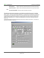
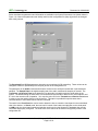
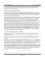
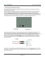
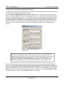
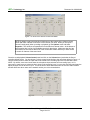
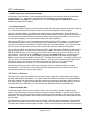
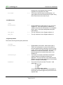
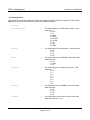
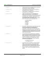
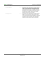
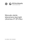
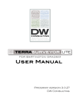
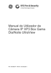
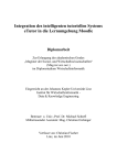
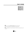
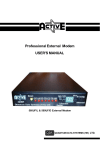
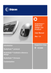
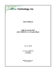
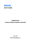
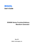
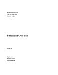
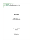
User's Manual
Simgars ASIP
Radio Simulation Software
Part No: 10469
Document No: MAN10469
Revision: C
Date: 28JAN11
eMDee Technology, Inc.
www.emdee.com
eMDee Technology, Inc.
Document No: MAN10469
Table of Contents
1.0 Installation and Setup..................................................................................................................................... 3
1.1 Software Installation................................................................................................................................... 3
1.2 Installing USB Drivers................................................................................................................................. 3
1.3 Launching the Application........................................................................................................................... 4
1.4 Menus and Configuration............................................................................................................................ 4
1.5 Using Audio with Simgars in Virtual Mode.................................................................................................. 7
1.6 Using PTT Switches with Simgars in Virtual Mode.....................................................................................7
1.7 Using Simgars with Simulated Hardware.................................................................................................... 8
1.8 Sound Card Configuration with Simulated Hardware..................................................................................9
1.9 USB Configuration with Simulated Hardware........................................................................................... 11
1.10 Testing the System................................................................................................................................. 11
2.0 Theory of Operation...................................................................................................................................... 11
2.1 Networked Audio (DIS)............................................................................................................................. 11
2.2 Dynamic Configuration Control................................................................................................................. 12
3.0 Configuration File Description...................................................................................................................... 13
3.1 [Host] Section........................................................................................................................................... 13
3.2 [DIS] Section............................................................................................................................................ 13
3.3 [USB] Section .......................................................................................................................................... 14
3.4 [System] Section....................................................................................................................................... 14
3.5 [Audio] Section......................................................................................................................................... 15
3.6 [Panel] Sections....................................................................................................................................... 17
3.7 [Radio] Sections....................................................................................................................................... 18
4.0 Tips, Troubleshooting, and Additional Information.......................................................................................23
4.1 Audio Capture Size.................................................................................................................................. 23
User's Manual, Simgars ASIP Radio Simulation Software
Page 2 of 23
eMDee Technology, Inc.
Document No: MAN10469
1.0 INSTALLATION AND SETUP
Install the software as outlined below before connecting any associated hardware to the system.
1.1 Software Installation
Insert the product CD into your CDROM drive. The installation program should launch automatically. If it does
not, run setup.exe from the root folder of the CD.
Figure 1.1: Simgars ASIP Installation Program
Follow the instructions in the installation program and keep the default settings unless there is a specific need to
change them. Once the installation program is complete, you may be prompted to restart your computer.
1.2 Installing USB Drivers
If you will be using the Simgars R/T simulated hardware, you will need to install the USB drivers before
continuing. To install the drivers, connect the USB cable from the Simgars R/T directly to your PC or through a
USB 2.0 hub that is connected to your PC. Windows will attempt to locate drivers for the new hardware – you
will need to specify a location for the drivers. The drivers will be installed to your computer into the folder:
C:\Program Files\Simgars\Drivers. To verify that the drivers have been installed correctly, open the Windows
Device Manager and look in the Universal Serial Bus controllers item. If the USB drivers were installed
properly, you should see an entry named: QuickUSB QUSB2 Module.
User's Manual, Simgars ASIP Radio Simulation Software
Page 3 of 23
eMDee Technology, Inc.
Document No: MAN10469
1.3 Launching the Application
During the installation, the setup program will create a folder in the Windows Start menu and a shortcut to the
application on the Windows desktop. You can launch the application by double-clicking the desktop icon or by
selecting Start/Programs/DisComm/Simgars ASIP.
Figure 1.2: Simgars ASIP Application Front Panel
1.4 Menus and Configuration
The menu bar at the top of the application window allow access to the different modes and pages of information
available in the application. The following menu options are available:
File
Exit – Closes and exits the application
View
Virtual Panels
Ctrl+1 – Shows the front panel in main window – this is the default view
Radio A Parameters
Ctrl+2 – Shows the virtual radio parameters for Radio A (see below)
Radio B Parameters
Ctrl+3 – Shows the virtual radio parameters for Radio B (see below)
User's Manual, Simgars ASIP Radio Simulation Software
Page 4 of 23
eMDee Technology, Inc.
Document No: MAN10469
ICS Parameters
Ctrl+4 – Shows the virtual radio parameters for intercom (see below)
System Parameters
Ctrl+5 – Shows miscellaneous parameters for the system (see below)
Help
About ASIP SINCGARS – Shows the product information and version
This application consists of three virtual radios. One for Radio A, one for Radio B, and one for a simulated
intercom. Each virtual radio has parameters associated with it that describe its characteristics. The window
below in Figure 1.3 shows the view for Radio A parameters. The initial value for the parameters are taken from
the application's main configuration file (Asip.cfg). Any of the parameters in this view can be changed during
runtime to alter the behavior of the virtual radio. Changing the value in this view is temporary and will not be
saved when the application exits. To change a value permanently, you will need to modify Asip.cfg (refer to
Section 3.0).
Virtual radio parameters can also be modified dynamically through a Remote Host Interface. This interface is
described in more detail in Section 2.2.
Figure 1.3: Virtual Radio Parameters View
User's Manual, Simgars ASIP Radio Simulation Software
Page 5 of 23
eMDee Technology, Inc.
Document No: MAN10469
Some miscellaneous parameters and information are available in the System Parameters view (shown below in
Figure 1.4). Most of the parameters are initially read from the configuration file (Asip.cfg) and can be changed
here during runtime.
Figure 1.4: System Parameters View
The BroadcastIP and IP Port parameters show the current settings for DIS networking. These values can be
changed at runtime or permanently from the [DIS] section of the configuration file.
The parameters in the Audio box determine how the audio from the configured sound card is processed and
sampled. The Sample Rate is the digital sampling rate of the audio, measured in samples per second. The
Transmit to and Receive From boxes determine how the audio is routed through the virtual radios in the
system. The default setting for these items is to transmit and receive audio to and from the virtual radios A and
B – this is the normal mode of operation. You may also select ICS in the Transmit to and Receive From boxes
in order to route the audio to/from the virtual intercom. This option is provided for special cases where
communications to a simulated vehicle intercom is desired.
The switch in the Front Panel box can be used to determine how to control the virtual panel in the main/default
view of the window. In Virtual mode, the user has full control of the buttons and switches on the virtual panel.
In USB mode, the virtual panel buttons and switches are driven from the Simgars R/T hardware that must be
connected and properly configured. The initial value of the switch can be set from the [System] section of the
configuration file.
User's Manual, Simgars ASIP Radio Simulation Software
Page 6 of 23
eMDee Technology, Inc.
Document No: MAN10469
The Host Data, Host Packet, and Valid Header? displays will contain helpful debugging information when
remote control of the software is being used. These displays will show the contents of the Remote Control
packets being received by the application.
1.5 Using Audio with Simgars in Virtual Mode
Using Simgars in virtual mode allows the user to operate the radio panels using a mouse or touch screen. In
virtual mode you can still use a headset for communications, but there are drawbacks. Most PC sound cards
only allow a mono microphone to be connected – even if a stereo input is connected to the microphone input, the
sound card will connect both channels together and you will not get the desired result. There are two options
available when using audio with virtual panels:
The first option is to use a hardware interface to connect two headsets to the line-in and line-out connections of
the sound card. Unlike the microphone input, the line-in input on most sound cards is stereo. But the line-in
input is not amplified, so an amplifier must be provided between the headset and line-in input to provide the
proper level to the sound card. This is one of the functions of the Simgars R/T hardware – it provides an
interface between two military handsets and the PC sound card. Proper amplification of the handset
microphones are provided within the box to allow a single connection to the stereo inputs of the PC sound card.
The second option of using two headsets with Simgars is to use two separate sound cards or a multi-channel
sound card. As long as Windows recognizes two sound cards in your system, you can use them with the
Simgars software. In this case, you will need to modify the configuration file (Asip.cfg) to assign the two sound
cards to the A and B radios. First, identify the names of the two sound cards by opening the Sound and Audio
Devices Control Panel in Windows. Enter the names from the playback device list exactly as shown into the
configuration file for the OutputA and OutputB entries under the [Audio] section. Likewise, enter the names
from the recording device list into the configuration file for the InputA and InputB entries. In this case, the
sound cards are treated as mono inputs, so you can connect a PC headset to each of the sound cards without
the need for splitting, combining, or amplifying the signals.
1.6 Using PTT Switches with Simgars in Virtual Mode
The push-to-talk (PTT) switch is the mechanism that enables the user to transmit on the virtual radio and
therefore communicate with other users on the audio network. There are several options available in virtual
mode for the PTT switch.
One option is to simply use the PTT software controls on the Simgars virtual radio panel located just to the right
of each panel. Click on the PTT switch to activate transmission from that virtual radio and click again to
deactivate.
Another option is to use the joystick/gameport input that is available on most PCs. If your PC has a joystick port
available, you can use this option. In the [System] section of the configuration file (Asip.cfg) set PTTMode=1 to
use joystick buttons as the interface to the PTT switches. You can use two buttons from a single joystick or you
can use one button from each of two joysticks, depending on your available hardware and system configuration.
Refer to Section 3.5 on how to set your configuration file to use a joystick for your PTT switches.
A third option for the PTT switches uses a combination of Simgars software and Simgars R/T hardware. This
mode is enabled when PTTMode=2 and uses the PTT switch inputs from the Simgars R/T hardware but ignores
any other buttons and switches from the hardware panels. This mode requires that the USB interface is enabled
and configured properly (refer to Section 3.3). In this mode, the displays and handset PTT switches will operate
on the Simgars R/T hardware, but the front panel buttons and switches can be controlled from the software
virtual panels. This creates a sort of “remote control” functionality for the radios.
User's Manual, Simgars ASIP Radio Simulation Software
Page 7 of 23
eMDee Technology, Inc.
Document No: MAN10469
1.7 Using Simgars with Simulated Hardware
When using the Simgars software with Simgars R/T hardware, you will need to set up the hardware and your
system as shown in this section.
The cabling between the Simgars R/T and your PC requires only two cables: a USB cable and an audio cable.
These two cables are supplied separately as PN 10534 and PN 10675, respectively. The USB cable (PN
10534) is a specialized cable that provides a circular locking connector on the peripheral end so the cable
cannot be accidentally disconnected (you may use a standard USB cable with a mini-Type B connector, but you
will not be able to use the locking feature on the Simgars R/T). Connect the locking end of the USB cable to the
Simgars R/T and the other end to a USB port on your PC or to a hub that is connected to the PC.
Figure 1.5: Rear View of Simgars R/T
Connect the circular locking connector of the audio cable (PN 10675) to the Simgars R/T and the other end to
your PC sound card. You can only use sound cards that have a line-in connection available. Most AC97
compliant sound cards will have this connection and it will be colored blue. The diagram below shows the proper
way to connect the Simgars R/T audio cable to a sound card. Connect the MIC wire to the line-in connector
(blue) on the sound card and connect the H'PHONE wire to the output connector (green) on the sound card.
NOTE: Do not connect the MIC wire to the microphone input of the sound card as this input is not compatible
with the Simgars R/T.
Figure 1.6: Connecting Simgars R/T to PC Sound Card
Simgars R/T is compatible with standard H-250 handsets that are used in many military applications. To get the
full capability from your Simgars R/T, connect two H-250 handsets to each of the AUD/DATA connectors on the
Simgars R/T radio panels.
User's Manual, Simgars ASIP Radio Simulation Software
Page 8 of 23
eMDee Technology, Inc.
Document No: MAN10469
1.8 Sound Card Configuration with Simulated Hardware
The steps in this section should be followed when using Simgars R/T hardware with H-250 handsets connected
to a single PC sound card with audio cable PN 10675.
Open the Sound and Audio Devices Control Panel in Windows (Start – Control Panel – Sound and Audio
Devices). Select the Audio tab at the top of the properties window. You should see a dialog box that is similar
to the screen capture shown below (Fig. 1.7). The device names in your system will likely be different as this is
dependent on your PCs configuration. If you only have one sound card in your system, the default device has
already been selected as that sound card. If your system has more than one audio device, you will need to
select the audio device from the drop-down lists that is connected to your Simgars R/T. Make the same ound
card selection for Sound playback and for Sound recording (MIDI music playback is not used and can be
ignored).
Figure 1.7: Sound and Audio Devices
Control Panel
Remember that all sound cards are not the same and the names and labels shown in these
figures are not necessarily the same as those for your sound card. All sound cards are
configured differently and have different numbers of features and capabilities. Most will have
controls for WAV playback and line-in adjustments – these are the controls that we are
referring to even though the names and labels may be different. In some cases it may be
necessary to experiment with the control panel to determine the correct controls to use.
Once you have selected the default devices, click the Volume button just below the Sound playback default
device. You should see a volume control panel similar to the one shown below in Figure 1.8. You can use this
control panel to adjust the audio levels that will be heard at the Simgars R/T. In the example shown below, you
would use the Wave volume control to adjust the level of audio coming from the radio network. Use the Input
Monitor volume control to adjust the level of your own voice – or sidetone. And use Volume Control to adjust
the overall audio level. Make sure that the Mute controls are not selected.
User's Manual, Simgars ASIP Radio Simulation Software
Page 9 of 23
eMDee Technology, Inc.
Document No: MAN10469
Figure 1.8: Sound Card Volume Control and Mixer
NOTE: By default, many sound cards will hide some of the controls in the Volume Control
panels and make it difficult to find some of the controls you need. When you first open a
Volume Control panel (either recording or playback) go the Options menu and select
Properties. This will show a Properties box for that device's internal mixer. At the bottom of
that Properties box is a list of all available controls for that device. Make sure that all of the
check boxes are checked so that none of the controls are hidden and that you have access
to control all features of the sound card.
Close the sound playback Volume Control panel and click on the Volume button just below the Sound
recording default device. You should see a volume control panel similar to the one shown below in Figure 1.9.
Use this control panel to select the input that will be routed to the recording input of the sound card's mixer.
NOTE: By default, most sound cards have the microphone input selected as the recording input, so it is
necessary to make sure you select the line-in input as the recording input. You may also use this control panel to
adjust the input level of the line-in input. This is the level of audio that will be sent out over the audio network
and will affect how other users on the network receive your voice transmissions.
Figure 1.9: Recording Control Selection
User's Manual, Simgars ASIP Radio Simulation Software
Page 10 of 23
eMDee Technology, Inc.
Document No: MAN10469
1.9 USB Configuration with Simulated Hardware
Configuration of the USB device is fairly straightforward as long as the correct drivers have been installed as
outlined in Section 1.2. If you will be using the Simgars R/T hardware you will need to set the item
Enabled=TRUE in the [USB] of the configuration file. The items USB_Type=3 and USB_ID=0 identify the
hardware and should not be changed.
1.10 Testing the System
Once all of the hardware has been connected, drivers loaded, and sound card configured, the system is ready to
run. Follow these steps to test the system to make sure you have configured the system properly:
Launch the Simgars software – you should see a window with two virtual radio panels. On the Simgars R/T
hardware, press a few of the keypad buttons and rotate the function switches while monitoring the virtual panels.
You should see the virtual panel buttons and switches change as you change the hardware. If you do not see
the virtual panel changing, you will need to double-check your USB configuration.
Now press the PTT button on one of the handsets connected to the Simgars R/T hardware. You should see the
corresponding PTT button on the virtual panel change to the enabled state. You should also be able to hear
your own voice (sidetone) in the handset. Perform the same test on the other handset. If you cannot hear your
own voice in one or both handsets, you will need to double-check the sound cabling and configuration.
Turn on CB1 (the switch on the lower-left of the Simgars R/T). Rotate the switch on Radio B (top radio panel) to
LD and rotate the switch on Radio A (bottom radio panel) to SQ ON. Note: When the function switch is in the
OFF, Z, or STBY positions, you will need to pull the switch toward you in order to move the switch in or out of
those locations. On Radio B, press the FREQ button followed by the MENU CLR button – the display should
show 5 dashes. Press 3, 2, 0, 0, 0, and then STO – the display should flash for a second and then display
32000. Using the handset from Radio B, press the PTT and speak into the handset. You should be able to hear
your own voice in the handset that is connected to Radio A. In this test you are transmitting from Radio B and
receiving on Radio A (you can also try the test by transmitting from Radio A). If you cannot hear the
transmission between the two radios, you will need to double-check your network settings.
Successfully performing the above tests will ensure that your system is configured properly for network
communications. If you have two or more systems that have passed these tests, you should now be able to
communicate between them over the audio network.
2.0 THEORY OF OPERATION
The intent of this manual is to familiarize the user with the setup, configuration, and operation of the Simgars
simulated radio software and hardware. The system intends to simulate the operation of a tactical SINCGARS
ASIP radio, however this manual does not attempt to describe the operation of the software where it pertains to
the tactical hardware. To get more information about how to operate the SINCGARS radio panels, refer to the
Army publication TM 11-5820-890-10-8 – Operators Manual, SINCGARS Ground Combat Net Radio.
2.1 Networked Audio (DIS)
The Simgars software utilizes an audio network to allow voice communication between multiple Simgars
stations. The audio network is based on the widely-used DIS simulation standard. In its basic sense, DIS is a
connectionless protocol that uses UDP/IP packets to send and receive information in real-time among network
participants. The Simgars software uses a subset of the DIS protocol to send and receive radio parametric data
and voice data.
The packets that are sent on the network are of two formats – transmitter data and signal data. The transmitter
data contains information about the virtual radio such as frequency, world position, modulation parameters, etc.
The signal data contains encoded digitized voice data. There are two basic things to remember when attempting
User's Manual, Simgars ASIP Radio Simulation Software
Page 11 of 23
eMDee Technology, Inc.
Document No: MAN10469
to communicate between more than one virtual radio. First, the combination of the Site ID, App ID, Entity ID,
and Radio ID must be different among all virtual radios on the network. These parameters uniquely identify each
virtual radio and must be different otherwise the radio software will be confused as to which radio is which. The
other thing to keep in mind is that the parametric data that is shared between the virtual radios must match in
order for the radios to be able to communicate. In other words, the frequency must be the same, the modulation
parameters must be the same, and the crypto parameters must the same. In a case where two virtual radios are
not communicating properly, double-check these two areas.
2.2 Dynamic Configuration Control
The Simgars software has the ability to statically set many parameters through a configuration file and
dynamically change those parameters through user controls on the front panel. In addition, many of these
parameters can be modified remotely through a Host Dynamic Configuration Control interface built into the
software. This allows a remote computer, such as a simulation Host, to control the Simgars software during
runtime without having to change the configuration file or have a user interact with the software.
The interface mechanism uses simple UDP/IP packets that are exchanged between the Simgars software and
the Host, and vice versa. The packet format is an extensible packet of variable length that contains a header
and footer along with “chunks” of data within the packet that describe the parameters of interest. The packet
format is explained in detail in our on-line help system:
http://www.emdee.com/icd_oview.php
The interface parameters that are available through the Simgars software is also detailed in our on-line help
system:
http://www.emdee.com/icd.php?pn=10469
The packets are variable length and need only contain the parameters that are of interest but must always
contain the header and footer words. An index is used to identify a specific radio in the system. In the Simgars
software Radio A is index 0 and Radio B is index 1.
The following packet is an example of how a Host computer would set the Crypto System and Crypto Key on
Radio A and set the DIS Entity ID on Radio B:
0xEAADEE
Required Header
0x3000D
\
0
| Set the Crypto System for Radio A to 5
5
/
0x3000E
\
0
| Set the Crypto Key for Radio A to 123
123
/
0x50011
\
1
|
90
| Set the DIS Entity ID for Radio B to 90/4/2
4
|
2
0xEAADEE
/
Required Footer
User's Manual, Simgars ASIP Radio Simulation Software
Page 12 of 23
eMDee Technology, Inc.
Document No: MAN10469
3.0 CONFIGURATION FILE DESCRIPTION
The following sections detail the entries in the configuration file for the Simgars Radio Software. The
configuration file can be found in C:\Program Files\Simgars and is named Asip.cfg. It can be edited with any
ASCII text editor such as Windows Notepad.
3.1 [Host] Section
[Host]
ReadPort=3030
<---
The IP port to be used for Host Dynamic Configuration
packets sent from the Host to the Simgars software
WritePort=3031
<---
The IP port to be used for Host Dynamic Configuration
packets sent from the Simgars software to the Host
WriteAdx=2.2.2.2
<---
The IP address of the Host – packets sent from the
Simgars software to the Host will be unicast to this
address
ByteSwap=TRUE
<---
Enable/disable byte swapping in the Host Dynamic
Configuration packets. This parameter is used for
compatibility between big endian and little endian
machines
3.2 [DIS] Section
This section sets the network parameters for DIS networking mode.
[DIS]
DISVersion=6
<---
An enumerated DIS value that indicates the DIS
protocol version being used:
4 = Ver 2.0 4th Draft
5 = IEEE 1278-1995
6 = IEEE 1278-1998
The Radio Software is compatible with version 4, 5, or
6. The default value should always be used except in
cases where compatibility with other systems is
required.
BroadcastIP=255.255.255.255
<---
The IP broadcast address for all DIS-transmitted
packets. In most cases the broadcast address can be
set to 255.255.255.255 which means “transmit to all
subnets”. In some cases, especially when there is
more than one network interface, this address will need
to be set to the subnet of the DIS network. For
example, if your IP address is 131.3.4.5 and the subnet
mask is 255.255.0.0, then the broadcast address
should be set to 131.3.255.255 to broadcast to that
subnet. The broadcast IP address does not affect
received packets, only transmitted packets. Any valid
User's Manual, Simgars ASIP Radio Simulation Software
Page 13 of 23
eMDee Technology, Inc.
Document No: MAN10469
packet that is on the network will be received,
regardless of the broadcast IP setting.
Port=3000
<---
The IP port of all DIS network communications. All
other systems that communicate with this system using
DIS will need to be on the same IP port.
Enabled=TRUE
<---
Enables/disables the USB interface to any connected
Simgars R/T. If the USB interface is enabled, the
software will search the USB interface for a compatible
device, open it, and begin passing data through the
USB interface.
USB_Type=3
<---
The only valid value for the Simgars software is 3.
USB_ID=0
<---
The only valid value for the Simgars software is 0.
3.3 [USB] Section
[USB]
3.4 [System] Section
This section sets the general system parameters.
[System]
Virtual=TRUE
<---
Enable/disable virtual mode. When virtual mode is
TRUE, the virtual panel is in control of the software –
the user interacts with the panel with a mouse or touchscreen. When virtual mode is FALSE, the Simgars R/T
hardware is in control of the software – the user
interacts through the simulated radio panels on the
Simgars R/T.
LaunchDelay=0
<---
The number of seconds to wait before the Simgars
software begins its initialization and starts the
application. This is provided for some instances when
Simgars must wait on other applications to fully initialize
before it can begin its initialization.
PTTMode=0
<---
The mode for the push-to-talk (PTT) switch. Valid
options are:
0 = Soft Panel
1 = Joystick
2 = USB
3 = USB Headset Interface
In Soft Panel mode, clicking the button labeled PTT on
the Simgars front panel triggers the push-to-talk for the
adjacent radio.
User's Manual, Simgars ASIP Radio Simulation Software
Page 14 of 23
eMDee Technology, Inc.
Document No: MAN10469
In Joystick mode, a joystick connected to the game port
will control the PTT switches for each radio. Joystick
button #1 will control the PTT for Radio A and joystick
button #2 will control the PTT for Radio B.
In USB mode, the PTT switches are read from the
Simgars R/T hardware but the other radio panel buttons
and switches are ignored. Use this mode in
combination with Virtual=TRUE to create a “remote
control” connection to Simgars R/T.
In USB Headset Interface mode, the PTT switch is read
from a USB Headset Interface box such as PN 10386.
Use this mode in combination with Virtual=TRUE to
create a virtual interface for instructors and/or
observers.
A_JoystickID=1
<---
When in joystick PTT mode (ref: PTTMode), this
parameter identifies which joystick/game port will be
used as PTT control for Radio A. Valid values are 1
through 16.
B_JoystickID=1
<---
When in joystick PTT mode (ref: PTTMode), this
parameter identifies which joystick/game port will be
used as PTT control for Radio B. Valid values are 1
through 16.
A_Button=1
<---
When in joystick PTT mode (ref: PTTMode), this
parameter identifies which button will be used as the
PTT control for Radio A. Valid values are 1 through 4.
B_Button=2
<---
When in joystick PTT mode (ref: PTTMode), this
parameter identifies which button will be used as the
PTT control for Radio B. Valid values are 1 through 4.
3.5 [Audio] Section
This section sets the parameters for the audio devices for the Radio Software.
[Audio]
InputA="[default]"
<---
The name of the audio input sound channel for Radio A.
The name of a specific sound card can be found in the
Windows Sound Control Panel. The default sound card
can be set in the Sound Control Panel. If InputA and
InputB are identical, the sound device will be shared
between the radios.
OutputA="[default]"
<---
The name of the audio output sound channel for Radio
A. The name of a specific card can be found in the
Windows Sound Control Panel. The default sound card
can be set in the Sound Control Panel. If OutputA and
OutputB are identical, the sound device will be shared
User's Manual, Simgars ASIP Radio Simulation Software
Page 15 of 23
eMDee Technology, Inc.
Document No: MAN10469
between the radios.
InputB="[default]"
The name of the audio input sound channel for Radio B.
The name of a specific sound card can be found in the
Windows Sound Control Panel. The default sound card
can be set in the Sound Control Panel. If InputA and
InputB are identical, the sound device will be shared
between the radios.
OutputB="[default]"
The name of the audio output sound channel for Radio
B. The name of a specific card can be found in the
Windows Sound Control Panel. The default sound card
can be set in the Sound Control Panel. If OutputA and
OutputB are identical, the sound device will be shared
between the radios.
CaptureSize=512
<---
The size of the audio capture buffer, in bytes. Lower
values will reduce audio delays but increase CPU and
network load.
SampleRate=8000
<---
The sample rate, in bytes per second, of the audio
capture buffer. This value may need to be changed for
compatibility with other systems.
User's Manual, Simgars ASIP Radio Simulation Software
Page 16 of 23
eMDee Technology, Inc.
Document No: MAN10469
3.6 [Panel] Sections
This section sets the initial conditions for each of the settings on the Simgars ASIP radio panel. There are two
Panel sections, one for Radio A (PanelA) and one for Radio B (PanelB).
[PanelA]
FunctionSwitch=5
<---
The initial position of the ASIP function switch. Valid
values are:
0 = OFF
1=Z
2 = REM
3 = RXMT
4 = SQ OFF
5 = SQ ON
6 = LD
7 = TST
8 = STBY
Power=1
<---
The initial setting for the radio power. Valid values are:
0 = LO
1=M
2 = HI
3 = PA
Mode=2
<---
The initial setting for the TRANSEC mode of the radio.
Valid values are:
0 = FH
1 = FHM
2 = SC
Channel=1
<---
The initial setting for the channel of the radio. Valid
values are:
0=M
1=1
2=2
3=3
4=4
5=5
6=6
7=C
Comsec=3
<---
The initial setting for the COMSEC mode of the radio.
Valid values are:
0 = CT
1 = RV
2 = TD
3 = PT
Volume=8
<---
The initial setting for the receiver volume of the radio.
Valid values are from 1 to 9.
User's Manual, Simgars ASIP Radio Simulation Software
Page 17 of 23
eMDee Technology, Inc.
Document No: MAN10469
PresetM=31.0
<---
Initial preset virtual frequency, in megahertz (MHz), for
the “M” channel of the virtual radio. The virtual radio
will be tuned to this frequency when the channel is set
to “M”.
Preset1=32.0
<---
Initial preset virtual frequency, in megahertz (MHz), for
channel 1 of the virtual radio. The virtual radio will be
tuned to this frequency when the channel is set to “1”.
Preset2=33.0
<---
Initial preset virtual frequency, in megahertz (MHz), for
channel 2 of the virtual radio. The virtual radio will be
tuned to this frequency when the channel is set to “2”.
Preset3=34.0
<---
Initial preset virtual frequency, in megahertz (MHz), for
channel 3 of the virtual radio. The virtual radio will be
tuned to this frequency when the channel is set to “3”.
Preset4=35.0
<---
Initial preset virtual frequency, in megahertz (MHz), for
channel 4 of the virtual radio. The virtual radio will be
tuned to this frequency when the channel is set to “4”.
Preset5=36.0
<---
Initial preset virtual frequency, in megahertz (MHz), for
channel 5 of the virtual radio. The virtual radio will be
tuned to this frequency when the channel is set to “5”.
Preset6=37.0
<---
Initial preset virtual frequency, in megahertz (MHz), for
channel 6 of the virtual radio. The virtual radio will be
tuned to this frequency when the channel is set to “6”.
PresetC=38.0
<---
Initial preset virtual frequency, in megahertz (MHz), for
the “C” channel of the virtual radio. The virtual radio will
be tuned to this frequency when the channel is set to
“C”.
3.7 [Radio] Sections
These sections set the simulated parameters of the virtual radios. The sections are labeled RadioA and RadioB
and correspond to the two virtual radios of the Simgars Radio Software.
[RadioX]
Enable=TRUE
<---
Enable/disable the virtual radio. Valid values are TRUE
and FALSE. When the radio is disabled (set to FALSE)
the virtual panel for that radio will not be seen in the
application window.
SiteID=100
<---
The DIS Site ID for this virtual radio. The combination
of Site ID, App ID, Entity ID, and Radio ID must be
unique throughout the network. Valid values are 1 –
65533. A randomized value will be used when set to
zero.
User's Manual, Simgars ASIP Radio Simulation Software
Page 18 of 23
eMDee Technology, Inc.
Document No: MAN10469
AppID=1
<---
The DIS Application ID for this virtual radio. The
combination of Site ID, App ID, Entity ID, and Radio ID
must be unique throughout the network. Valid values
are 1 – 65533. A randomized value will be used when
set to zero.
EntityID=1
<---
The DIS Entity ID for this virtual radio. The combination
of Site ID, App ID, Entity ID, and Radio ID must be
unique throughout the network. Valid values are 1 –
65533. A randomized value will be used when set to
zero.
RadioID=1
<---
The DIS Radio ID for this virtual radio. The combination
of Site ID, App ID, Entity ID, and Radio ID must be
unique throughout the network. Valid values are 1 –
65533. A randomized value will be used when set to
zero.
ExerciseID=1
<---
Sets the DIS exercise ID for the virtual radio. The
exercise ID defines a "virtual world" that radios
communicate in. This setting allows the physical
network to be divided into separate "worlds" so that
radio communication can be segregated. Radios and
intercoms with different exercise IDs will not be able to
communicate regardless of any other settings.
Encoding=1
<---
DIS enumeration for the type of encoding used in
transmitted audio packets:
1 = mu-Law
2 = CVSD
3 = ADPCM
4 = 16 bit PCM
7 = CECOM CVSD
Gain=1.0
<---
Sets the gain of the input stage of the virtual radio
model. The input stage consists of the combined effects
of the antenna and input amplifier of the simulated radio
system. The effects of the transmitter's power, the
signal propagation loss due to relative positions, and
the receiver gain determine the strength of the received
signal. The input gain is measured in decibels (dB).
Typical gain settings range from 1.0 to 20.0.
Bandwidth=100.0
<---
Sets the bandwidth for a virtual radio tuner model.
Along with the tuned frequency, this parameter sets a
bandpass filter for the virtual radio whereas if an
incoming signal's frequency is within this band, it will
pass through the tuner model.
User's Manual, Simgars ASIP Radio Simulation Software
Page 19 of 23
eMDee Technology, Inc.
System=5
Document No: MAN10469
<---
Sets the modulation system for a virtual radio. If the
system parameters do not match between two radios,
those radios will not be able to communicate. Valid
values for this parameter are:
0 = Other
1 = Generic
2 = Have Quick
3 = Have Quick II
4 = Have Quick IIA
5 = SINCGARS
6 = CCTT SINCGARS
Modulation=11
<---
Sets the modulation mode for a virtual radio. If the
modulation parameters do not match between two
radios, those radios will not be able to communicate.
Valid values for this parameter are:
0 = AM AFSK (1, 1)
1 = AM AM (1, 2)
2 = AM CW (1, 3)
3 = AM DSB (1, 4)
4 = AM ISB (1, 5)
5 = AM LSB (1, 6)
6 = AM SSB Full (1, 7)
7 = AM SSB Reduced (1, 8)
8 = AM USB (1, 9)
9 = AM VSB (1, 10)
10 = Amplitude and Angular (2, 1)
11 = Angular FM (3, 1)
12 = Angular FSK (3, 2)
13 = Angular PM (3, 3)
14 = CM AAP (4, 1)
15 = Pulse (5, 1)
16 = Unmodulated (6, 1)
PropLoss=1
<---
Enable/disable the propagation loss model for the
virtual radio. The propagation loss model calculates the
loss of signal based on tuned frequency, transmitted
power, receiver gain, and distance between transmitter
and receiver. When the model is disabled, received
signals are not attenuated due to propagation.
RoundEarth=1
<---
Enable/disable the round earth model for the virtual
radio. The round earth model calculates the loss of
signal based on line of sight (LOS) between the
transmitter and receiver. When the model is disabled,
received signals are not attenuated due to the horizon.
Tuner=1
<---
Enable/disable the tuner model for the virtual radio.
The tuner model verifies that the frequency of the
transmitter falls within the tuned frequency and
bandwidth of the receiver. When the model is disabled,
received signals are not attenuated due to frequency.
User's Manual, Simgars ASIP Radio Simulation Software
Page 20 of 23
eMDee Technology, Inc.
Document No: MAN10469
FreqHop=0
<---
Enable/disable frequency hopping mode for simulation
of transmission security (TRANSEC).
PseudoNoise=0
<---
Enable/disable pseudo noise mode for simulation of
transmission security (TRANSEC).
TimeHop=0
<---
Enable/disable time hopping mode for simulation of
transmission security (TRANSEC).
CryptoSystem=0
<---
A DIS enumerated value for the simulated crypto
system for the virtual radio. The combination of
CryptoSystem and CryptoKey sets the simulated secure
transmission mode. Basically, if the listening radio is
set to the same crypto system and key, the
transmission will be heard, otherwise only noise will be
heard. Valid values for the CryptoSystem are:
0 = Other (disabled)
1 = KY-28
2 = KY-58
3 = NSVE
4 = WSVE
5 = ICOM
CryptoKey=0
<---
An arbitrary value that represents the software key that
was used to scramble the transmitted signal. If a
receiver has the same key to descramble the
transmission, it will properly receive the transmission,
otherwise only noise will be received. This value is only
a simulated key and the transmitted data is not actually
scrambled, but this allows simulation of the effects of a
secure radio transmission.
PosnMode=1
<---
An enumerated value that represents the coordinate
system being used to define the position of the virtual
radio. In geodetic mode, the coordinates will be treated
as latitude, longitude, and altitude data. In geocentric
mode, the coordinates will be treated as x, y, and z
components measured from the center of the Earth.
The values for PosnMode are:
0 = Geodetic (lat, long, alt)
1 = Geocentric (x, y, z)
PosnX_Lat=0.0
<---
In geocentric mode, the distance in meters along the
Earth's X axis. The positive X axis originates at the
center of the Earth and extends through the prime
meridian at the equator. In geodetic mode, the latitude
of the virtual radio is measured in degrees from the
equator. Positive values indicate latitudes north of the
equator.
User's Manual, Simgars ASIP Radio Simulation Software
Page 21 of 23
eMDee Technology, Inc.
Document No: MAN10469
PosnY_Long=0.0
<---
In geocentric mode, the distance in meters along the
Earth's Y axis. The positive Y axis originates at the
center of the Earth and extends through 90 degrees
east longitude at the equator. In geodetic mode, the
longitude of the virtual radio is measured in degrees
from the prime meridian. Positive values indicate
longitudes east of the prime meridian.
PosnZ_Alt=0.0
<---
In geocentric mode, the distance in meters along the
Earth's Z axis. The positive Z axis originates at the
center of the Earth and extends through the north pole.
In geodetic mode, the altitude of the virtual radio is
measured in meters above mean sea level (MSL).
User's Manual, Simgars ASIP Radio Simulation Software
Page 22 of 23
eMDee Technology, Inc.
Document No: MAN10469
4.0 TIPS, TROUBLESHOOTING, AND ADDITIONAL INFORMATION
4.1 Audio Capture Size
The audio capture buffer is a buffer that accepts sampled audio from an audio device and readies it for
transmission to the network. The capture buffer size in DisCommWin is configurable and its optimal size
depends on a number of factors. Since the sampled audio is buffered, there will be a time delay between the
first sampled data and the time the packet is sent to the network. The time delay is roughly calculated by taking
the number of bytes in the capture buffer divided by twice the sample rate of the audio capture (the audio device
captures 16 bit samples). So it can be seen that increasing the buffer size will increase the time delay and
decreasing the buffer size will decrease the time delay. As the buffer size is decreased, the load on the CPU
and the network mechanism increases. This is because the same amount of information must be passed in
smaller packets – this translates to a larger number of packets per second.
The size of the network packets that are generated by the audio capture process is dependent on the capture
buffer size, and also the encoding algorithm being used. As an example, let us assume that the sample rate is
set to 8000 samples per second, the capture buffer is set to 1024 bytes, and the encoding is set to mu-Law
(which has a 2-to-1 compression ratio). The capture buffer will hold 512 samples (each sample is 16 bits) and
those samples will be compressed to a packet size of 512 bytes. It will take 64 milliseconds to capture the
contents of the buffer.
Compression ratios for the encoding algorithms:
● mu-Law
2-to-1
● CVSD
16-to-1
● ADPCM
4-to-1
● 16 bit PCM
1-to-1
User's Manual, Simgars ASIP Radio Simulation Software
Page 23 of 23