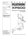
1
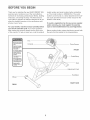
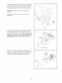
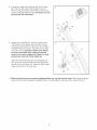
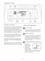
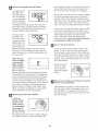
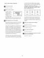
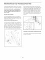
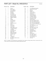
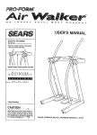
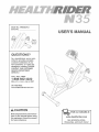
®
ModeJ No. HRE×2076.0
Serial No.
USER'S
As a manufacturer, we are committed to providing complete
customer satisfaction, if you
have questions, or if parts are
damaged or missing, PLEASE
CONTACT OUR CUSTOMER
SERVICE DEPARTMENT
DIRECTLY.
CALL TOLL-FREE:
1-888-922-4222
Mon.-Fri.,
6 a.m.-6 p.m. MST
ON THE WEB:
www.health riderservice.com
our website
Read all precautions and instructions in this manual before using
this equipment, Keep this manual
for future reference,
a_
www.healthrider.com
new products,
prizes,
fitness tips, and much more!
TABLE OF CONTENTS
IMPORTANT PRECAUTIONS
................................................................
BEFORE YOU BEGIN ......................................................................
ASSEMBLY ...............................................................................
HOW TO OPERATE THE EXERCISE CYCLE ....................................................
MAINTENANCE AND TROUBLESHOOTING
...................................................
CONDITIONING GUIDELINES ...............................................................
PART LIST ..............................................................................
EXPLODED DRAWING ....................................................................
ORDERING REPLACEMENT PARTS ..................................................
LIMITED WARRANTY ..............................................................
2
3
4
8
12
13
14
15
Back Cover
Back Cover
IMPORTANT PRECAUTIONS
AWARNING. Toreduce
theriskofserious
injury,
read
the
fo,owing
important
precautionsbefore using the exercise cyde.
M
Read all instructions
inthis manual and a_l
warnings on the exercise cycle before using
_he exercise cycle. Use the exercise cycle
only as described in this manual
2. It is the responsibility
of the owner to ensure
that aH users of the exercise cycle are adequateJy informed of aH precautions.
3. The exercise cycle is intended for home use
onJy. Do not use the exercise cycle in
a commercial
rental, or institutional setting,
4,
Keep the exercise cycle indoors, away from
moisture and dust= Place the exercise cycJe
on a [eveJ surface, with a mat beneath it to
protect the floor. Make sure that there is
enough clearance around the exercise cycle
to mount, dismount, and use it.
5. Inspect and properly tighten aH parts regularly. Replace any worn parts immediately.
6. Keep children under the age of 12 and pets
away from the exercise cycle at aH times.
7. The exercise cycle should not be used by
persons weighing more than 250 pounds.
8. Wear appropriate clothes when exercising;
do not wear loose clothes that could become
caught on the exercise cycle= Always wear
athletic shoes for fool protection.
9. The pulse sensor is not a medical device.
Various factors, including the user's movement. may affect the accuracy of heart rate
readings. The pulse sensor is intended onty
as an exercise aid in determining
heart rate
trends in general
10. Always keep your back straight when using
the exercise cycle; do not arch your back.
11. ff you feel pain or dizziness while exercising,
stop immediately and cool down.
12. The exercise cycle does not have a freewheel; the pedals will continue to move until
the flywheel stops.
13.The decaJ shown on page 3 has been placed
on the exercise eyrie, if the decal is missi ng
or illegible, call the toll-free telephone number on the front cover of this manuaJ and
order a free replacement decal Apply the
deeam in the location shown.
A WARNING: Beforo
beginning
th_s
oranyexorc_ae
program,
consult
yourphysician. This
is especially important for persons over the age of 35 or persons with pre-e×isting heaJth problems.
Read aH instructions
before using. ICON assumes no responsibility
for personal injury or property
damage sustained by or through the use of this product.
BEFORE YOU BEGIN
Thank you for selecting the new HEALTHRIDER _'_
N35
exercise cycle, Cycling is one of the most effective
exercises for increasing cardiovascular fitness, building
endurance, and toning the body, The N35 exercise
cycle offers a selection of features designed to let you
enjoy this healthful exercise in the convenience and
privacy of your home,
For your benefit, read this manuaJ carefully before
you use the exercise cycJe. If you have questions
after reading this manual, please see the front cover
of this manual, To help us assist you, note the product
model number and serial number before contacting
us. The model number is HREX2076,0, The sedal
number can be found on a decal attached to the exercise cycle (see the front cover of this manual for the
location of the decal),
To avoid a registration fee for any service needed
under warranty, you must register the exercise
cycle at www.bealtbriderserviceocom/registration.
Before reading further, please familiarize yourself with
the parts that are labeled in the drawing below,
Fan
Console
Pulse Sensor
FRONT
Seat
'\
\
//
Adjustment Knob
Handlebar
Wheel
RIGHT SIDE
REAR
Tohire anauthorizedservicetechnicianto assemblethe exercise
cycle, call toll°free
1°800-445-2480o
Assembly requires two persons. Place all parts of the exercise cycle in a cleared area and remove the packing materials. Do not dispose of the packing materials until assembly is completed. Jn addition to the included
hex keys, assembly
requires
a phillips
screwdriver
(_:_
and an adjustable
wrench _4.
As you assemble the exercise cycle, use the drawings below to identify small parts. The number in parentheses
below each drawing is the key number of the part, from the PART LIST on page 14. The number following the key
number is the quantity needed for assembly. Note: Some small parts may have been preassembled, tf a part
is not in the parts bag, check to see if it has been preassembted.
M6 Washer
(55)-8
M8 Split
Washer (59)-5
M4 x 16mm
Round Head
Screw (52)-4
M8 Nylon
Locknut (60)-4
M6 x 38mm Button
Screw (48)-4
M8 x 25mm Button
Screw (33)-3
M10 Nylon
Locknut (63)-4
M6 x 42mm Button
Screw (49)-4
M8 x 70mm Button
Bolt (54)-2
M10 x 75mm Carriage Bolt (51)-4
1
To make assembly easier, read the information
on page 4 before you begin assembling the
exercise cycle.
While another person lifts the front of the Frame (1),
attach the Front Stabilizer (3) to the Frame with two
M10 x 75mm Carriage Bolts (51) and two M10 Nylon
Locknuts (63).
See the inset drawing. Loosen the Adjustment Knob
(17), slide the Rear Frame (2) out of the Frame (1),
and then retighten the Adjustment Knob.
2. Attach the Wheels (18) to the Rear Stabilizer (4) with
two M8 Nylon Locknuts (60). Press a Wheel Cap (19)
onto each Wheel.
Attach the Rear Stabilizer (4) to the Rear Frame (2)
with two M10 x 75mm Carriage Bolts (51) and two
M10 Nylon Locknuts (63).
3. Attach a Seat Frame (7) to the Handlebar (6) with an
M8 x 70mm Button Bolt (54), an M8 Split Washer (59),
and an M8 Nylon Locknut (60). Do not tighten the
Button Bolt yet.
Attach the other Seat Frame (7) in the same way.
4. Slide the Seat Frame Top (8) onto the Seat Frames
(7). Attach the Backrest (5) to the Seat Frames and
the Seat Frame Top with four M6 x 38mm Button
Screws (48) and four M6 Washers (55). Do not tighten the Button Screws yet.
5
8
/
Have another person hold the Seat Frames (7) under
the Rear Frame (2) as shown, Attach the Seat Frames
and the Seat (12) to the Rear Frame with four M6 x
42ram Button Screws (49) and four M6 Washers (55),
See step 3. Tighten the two M8 x 70mm Button
Bolts (54),
/
/
/
/
See step 4. Tighten the four M6 x 38mm Button
Screws (48),
/
49
The Console (16) requires four D batteries (not included); alkaline batteries are recommended, Press the
tab on the battery door and remove it, Insert four batteries into the Console as shown, Make sure that the
16
batteries are oriented as shown by the diagram on
the battery door. Then, reattach the battery door,
Batteries
Tab
Battery Door
Connect the console wire harness to the Upper Wire
Harness (36), Insert the console wire harness into the
Upright (13), Attach the Console (16) to the Upright
with four M4 x 16mm Round Head Screws (52),
Console
Wire
Harn_
52
\
36
16
8.
Connect the Upper Wire Harness (36) to the Lower
Wire Harness (65)_ Attach the Upright (13) to the
Frame (1) with three M8 x 25mm Button Screws (33)
and three M8 Split Washers (59). Be careful to avoid
pinching the Wire Harnesses.
8
13
36
,
Identify the Left Pedal (24), which is marked with a
"Left" sticker. Firmly tighten the Left Pedal counterclockwise into the left arm of the Crank (31). Tighten
the Right Pedal (not shown) clockwise into the right
arm of the Crank. Important: Tighten both PedaJs
as firmly as possible. After using the exercise
cycle for one week, retighten the Pedals. For best
performance, keep the PedaJs tightened.
31
25
Adjust the Left Pedal Strap (25) to the desired position, and press the end of the Left Pedal Strap onto
the tab on the Left Pedal (24). Adjust the Right Pedal
Strap (not shown) in the same way.
24
Tab
10. Make sure that aH parts are properly tightened before you use the exercise cycle. Note: Some hardware
may be left over after assembly is completed. Place a mat beneath the exercise cycle to protect the floor.
7
HOW "TO OPERATE "THE EXERCISE CYCLE
HOW TO ADJUST THE SEAT
After the exercise cycle is assembled, adjust the Seat (12)
to the proper position. As you pedal, there should be a
slight bend in your knees when the pedals are in the farthest forward position. Loosen the Adjustment Knob (17),
slide the Rear Frame (2) forward or backward in the
Frame (1), and then tighten the Adjustment Knob.
12
1
2
DtAGRAMOFTHECONSOLE
Fan
Button
Program
Profiles
Increase
Button
MPH
PROGRAM
RPM
t
I
Program Button
Program
Indicator
Display
FEATURES OF THE CONSOLE
Pace
Guide
Decrease
Button
HOW TO USE THE MANUAL MODE
This advanced console offers a selection of features
designed to make your workouts more effective. When
you use the manual mode of the console, you can
change the resistance of the pedals with the touch of a
button. As you pedal, the console will provide continuous exercise feedback. You can even measure your
heart rate using the built-in handgnp pulse sensor.
Turn on the consoJe.
To turn on the console, press the Increase button
or begin pedaling. The pace guide will light for a
moment; the console will then be ready for use.
Select the manual mode.
The console also offers five preset programs that automatically change the resistance of the pedals and
prompt you to vary your pedaling pace whib guiding
you through an effective workout.
When you turn on the console, the manual mode
will be selected. If you have selected a program,
resebct the manual mode by pressing the
Program button repeatedly until no program indicators (see the drawing above) appear along the
left side of the display.
To use the manual mode of the console, see the
instructions at the right. To use a preset program,
see page 11.
I Change the resistance
Before using the console, make sure that batteries are
installed (see assembly step 6 on page 6). If there is a
sheet of clear plastic on the display, remove the plastic.
of the pedals as desired.
As you pedal,
change the resistance of the pedals
by pressing the
Increase and
Decrease buttons.
There are ten resistance levels. Note: After you press the buttons, it
will take a moment for the pedals to reach the
selected resistance level.
9
Follow your progress
The upper half of
the display will
show the elapsed
time, the distance
you have pedaled,
and the resistance
with the display.
heart-shaped indicator in the lower half of the display will flash each time your heart beats, and
then your heart rate will appear in the display,
ce ce" F1
tR
For the most accurate heart rate reading, continue
to hold the handgrip pulse sensor for about 30
seconds, Note: If you continue to hold the handgrip pulse sensor, the display will show your heart
rate for about 30 seconds, The display will then
show your heart rate along with the other modes,
XME
J
level of the pedals,
The display will change modes every few seconds, Note: When a preset program is selected,
the display will show the time remaining in the
program instead of the elapsed time,
If your heart rate does not appear, make sure that
your hands are positioned as described. Avoid
moving your hands excessively or squeezing the
metal contacts too tightly, For optimal performance, periodically clean the metal contacts
using a soft cloth; never use alcohol, abrasives,
or chemicals to dean the contacts.
The lower half of
the display will
show your pedaling speed and the
approximate number of calories you
have burned, The
_U
Turn on the fan if desired.
To turn on the fan at low speed, press the Fan
button, To turn on the fan at high speed, press
the Fan button a second time, To turn off the fan,
press the Fan button a third time, Note: If the fan
is turned on but the pedals do not move for thirty
seconds, the fan will automatically turn off to conserve the batteries,
display will change modes every few seconds,
The lower half of the display will also show your
heart rate when you use the handgrip pulse sensor (see step 5),
Note: The con=
sole can display
speed and dis_W
_'_
tance in either
L
miles or HIometers. The letters
MPH or KMiH will
appear in the lower half of the display to indicate
the selected unit of measurement, To change the
unit of measurement, first hold down the Program
button for several seconds, An E (for English) or
an M (for metric) will appear in the display, Press
the Increase button to change the unit of measurement, When the desired unit of measurement is
Rotate the thumb
tab on the right
side of the fan to
Thumb
adjust the angle of
the fan,
When you are finished exercising,
wHI turn off automaticaHyo
selected, press the Program button again, Note:
When you replace the batteries, it may be necessary to reselect the unit of measurement,
the console
If the pedals do not move for a few seconds, the
time will begin to flash in the display and the console will pause, If the pedals do not move for a
few minutes, the console will turn off and the display will be reset,
Measure your heart rate if desired.
tf there are
sheets of clear
plastic on the
metal contacts
on the handgrip
pulse sensor,
remove the plastic. Next, hold the
handgnp pulse sensor with your palms resting on
the contacts, When your pulse is detected, the
10
Turn
on the
one of the two lower indicators lights, increase
your pace; when one of the two upper indicators
lights, decrease your pace, When the center indicator lights, maintain your current pace,
Important: The pace guide is intended onJy to
provide a goal Make sure to pedal at a pace
that is comfortable for you.
console.
See step 1 on page 9,
Select a preset program.
v
To select a preset
program, press the
Program button
repeatedly until the
number 1, 2, 3, 4,
or 5 appears along
the left side of the
@
RPM
RPM
RPM
The display will show the time remaining in the
program, If you stop pedaling for a few seconds,
the program will pause and the time will flash in
the display, To restart the program, simply resume
pedaling,
display, When you select a preset program, the
display will show how long the program will last,
Begin pedaJing to start the program.
Each preset programs consists of 30 one-minute
segments, One resistance level and one target
pace are programmed for each segment,
Follow your progress
At the end of each segment, the resistance level
will flash in the display for a few seconds, The
resistance of the pedals will then automatically
change to the resistance level programmed for
the next segment, Note: If the resistance level is
too low or too high, you can override it by pressing the hcrease and Decrease buttons, However,
when the current segment ends, the resistance
wiiI automatically change to the resistance level
programmed for the next segment,
Measure your heart rate if desired.
with the disptay.
See step 4 on page 10,
See step 5 on page 10,
Turn on the fan if desired.
See step 6 on page 10,
When you are finished exercising,
wHI turn off automatically.
During the program, the pace guide will prompt
you to keep your pedaling pace near the target
pace programmed for the current segment, When
See step 7 on page 10,
11
the consote
MAINTENANCE
AND TROUBLESHOOTING
With the left side shield removed, locate the Reed
Switch (43). Turn the Crank (31) until the Magnet (38)
is aligned with the Reed Switch. Next, loosen, but do
not remove, the indicated M4 x 16mm Screw (57).
Slide the Reed Switch slightly closer to or away from
the Magnet, and then retighten the Screw. Turn the
Crank for a moment. Repeat until the console displays correct feedback. When the Reed Switch is correctly adjusted, reattach the left side shield and the
left pedal.
Inspect and properly tighten all parts of the exercise
cycle regularly. Replace any worn parts immediately.
To clean the exercise cycle, use a damp cloth and a
small amount of liquid dish soap. Important: To
avoid damaging the console, keep liquids away
from the console and keep the consoJe out of
direct sunlight.
BATTERY REPLACEMENT
If the console display becomes dim, the batteries
should be replaced; most console problems are the
result of low batteries. To replace the batteries, see
assembly step 6 on page 6.
HOW TO ADJUST THE REED SWITCH
If the console does not display correct feedback, the
reed switch should be adjusted. To adjust the reed
switch, you must first remove the Left Side Shield (9).
Using an adjustable wrench, turn the Left Pedal (24)
clockwise and remove it. Next, remove the seven
M4 x 16mm Screws (57) and the M4 x 25mm Screw
(45). Then, carefully remove the Left Side Shield.
HANDGRIP PULSE SENSOR TROUBLESHOOTING
If the handgrip pulse sensor does not function properly,
see step 5 on page 10.
/
57,
\
57
45
57
12
CONDmONmNG
GUmDELmNES
The following guidelines will help you to plan your
exercise program. Remember that proper nutrition
and adequate rest are essential for successful results.
During the first few minutes of exercise, your body
uses easily accessible carbohydrate calories for energy. Only after the first few minutes of exercise does
your body begin to use stored fat calories for energy.
If your goal is to burn fat, adjust the intensity of your
exercise until your heart rate is near the lowest number in your training zone as you exercise.
A WARNING: Before
beginning
this or any exercise program, consult your
physician. This is especially important for
persons over the age of 35 or persons with
pre-e×isting health problems,
The pulse sensor is
Various factors may
heart rate readings.
intended onJy as an
ing heart rate trends
For maximum fat burning, adjust the intensity of your
exercise until your heart rate is near the middle of
your training zone as you exercise.
not a medical device.
affect the accuracy of
The pulse sensor is
exercise aid in determinin general
AerobicExercise
If your goal is to strengthen your cardiovascular system, your exercise must be "aerobic." Aerobic exercise is activity that requires large amounts of oxygen
for prolonged periods of time. This increases the
demand on the heart to pump blood to the muscles,
and on the lungs to oxygenate the blood. For aerobic
exercise, adjust the intensity of your exercise until
your heart rate is near the highest number in your
training zone.
EXERCISE iNTENSiTY
Whether your goal is to burn fat or to strengthen your
cardiovascular system, the key to achieving the
desired results is to exercise with the proper intensity.
The proper intensity level can be found by using your
heart rate as a guide. The chart below shows recommended heart rates for fat burning, maximum fat
burning, and cardiovascular (aerobic) exercise.
165 155 145
140 130 125
115
_
145 138 130
125
118 110
103
q,_)
125 120 115 110 105 95
90
20
80
30
40
50
60
70
WORKOUT
GUIDEUNES
Each workout should include the following three parts:
A warm-up, consisting of 5 to 10 minutes of stretching
and light exercise. A proper warm-up increases your
body temperature, heart rate, and circulation in preparation for exercise.
Training zone exercise, consisting of 20 to 30 minutes of exercising with your heart rate in your training
zone. Note: During the first few weeks of your exercise program, do not keep your heart rate in your
training zone for longer than 20 minutes.
To find the proper heart rate for you, first find your age
at the bottom of the chart (ages are rounded off to the
nearest ten years). Next, find the three numbers above
your age. The three numbers are your "training zone."
The lowest number is the recommended heart rate for
fat burning, the middle number is the recommended
heart rate for maximum fat burning, and the highest
number is the recommended heart rate for aerobic
exercise.
A cooJ-down, with 5 to 10 minutes of stretching. This
will increase the flexibility of your muscles and will
help to prevent post-exercise problems.
EXERCBE
FREQUENCY
To maintain or improve your condition, plan three workouts each week, with at least one day of rest between
workouts. After a few months of regular exercise, you
may complete up to five workouts each week, if
desired. Remember, the key to success is make exercise a regular and enjoyable part of your everyday life.
Fat Burning
To burn fat effectively, you must exercise at a relatively low intensity level for a sustained period of time.
13
PART LIST--Model
Key No. Qty.
1
2
3
4
5
6
7
8
9
10
11
12
13
14
15
16
17
18
19
20
21
22
23
24
25
26
27
28
29
30
31
32
33
34
1
1
1
1
1
1
2
1
1
1
2
1
1
1
1
1
1
2
2
1
1
1
1
1
1
1
1
1
1
1
1
1
3
1
No. HREX2076.0
Description
ROTO6A
Key No. Qty.
Frame
Rear Frame
Front Stabilizer
Rear Stabilizer
Backrest
Handlebar
Seat Frame
Seat Frame Top
Left Side Shield
Right Side Shield
Stabilizer Endcap
Seat
Upright
Front Bushing
Rear Bushing
Console
Adjustment Knob
Wheel
Wheel Cap
Frame Pad
Frame Stop
Reed Switch Clamp
C-magnet Bracket
Left Pedal
Left Pedal Strap
Right Pedal
Right Pedal Strap
Resistance Motor
Flywheel Axle
Belt
Pulley/Crank
C-magnet
M8 x 25mm Button Screw
Flywheel
35
36
37
38
39
40
41
42
43
44
45
46
47
48
49
50
51
52
53
54
55
56
57
58
59
60
61
62
63
64
65
#
#
1
1
2
1
2
1
1
1
1
2
3
1
1
4
4
3
4
4
1
2
8
1
12
4
5
5
6
2
4
1
1
1
2
Description
Crank Bearing Assembly
Upper Wire Harness
Bearing
Magnet
Tension Bolt
Tension Bracket
M8 Washer
Flywheel Washer
Reed Switch/Wire
Handlebar Endcap
M4 x 25mm Screw
Resistance Cable
Return Spring
M6 x 38mm Button Screw
M6 x 42mm Button Screw
M4 x 16mm Flat Head Screw
M10 x 75mm Carriage Bolt
M4 x 16mm Round Head Screw
5mm Spacer
M8 x 70mm Button Bolt
M6 Washer
M8 x 20mm Button Bolt
M4 x 16mm Screw
M5 Washer
M8 Split Washer
M8 Nylon Locknut
M6 Nut
M8 Jam Nut
M10 Nylon Locknut
M6 x 38mm Bolt
Lower Wire Harness
User's Manual
Hex Key
Note: "#" indicates a non-illustrated part, Specifications are subject to change without notice, See the back cover
of this manual for information about ordering replacement parts,
14
EXPLODED
DRAWING--Model
No. HREX2076.0
ROTO6A
44
/
/
/
/
j/
60
57 _
s
12
57
45
49
5O
6O
18
16
63
18
33
11.
19
51
29
35
34
53
61
4O
35
30
32
38
14
61
26
45
56
15
15
ORDERING
REPLACEMENT
PARTS
To order replacement parts, see the front cover of this manual, To help us assist you, please be prepared to
provide the following information when contacting us:
• the MODEL NUMBER of the product (HREX2076,0)
• the NAME of the product (HEALTHRIDER
N35 exercise cycle)
• the SERIAL NUMBER of the product (see the front cover of this manual)
• the KEY NUMBER and DESCRIPTION
HEALTHRIDER
of the part(s) (see page 14)
is a registered trademark of ICON IP, Inc,
LIMITED WARRANTY
ICON Health & Fitness, Inc, (ICON) warrants this product to be free from defects in workmanship and
material, under normal use and service conditions, for a period of ninety (90) days from the date of purchase, This warranty extends only to the original purchaser, ICON's obligation under this warranty is limited to replacing or repairing, at ICON's option, the product through one of its authorized service centers,
All repairs for which warranty claims are made must be pre=authodzed by ICON, If the product is shipped
to a service center, freight charges to and from the service center will be the customer's responsibility, For
in=home service, the customer will be responsible for a minimal trip charge, This warranty does not extend
to any product or damage to a product caused by or attributable to freight damage, abuse, misuse,
improper or abnormal usage or repairs not provided by an ICON authorized service center; products used
for commercial or rental purposes; or products used as store display models, No other warranty beyond
that specifically set forth above is authorized by ICON,
ICON is not responsible or liable for indirect, special or consequential damages arising out of or in connection with the use or performance of the product or damages with respect to any economic loss, loss
of property, loss of revenues or profits, loss of enjoyment or use, costs of removal or installation or other
consequential damages of whatsoever nature, Some states do not allow the exclusion or limitation of incidental or consequential damages, Accordingly, the above limitation may not apply to you,
The warranty extended hereunder is in lieu of any and all other warranties and any implied warranties of
merchantability or fitness for a particular purpose is limited in its scope and duration to the terms set forth
herein, Some states do not allow limitations on how long an implied warranty lasts, Accordingly, the above
limitation may not apply to you,
This warranty gives you specific legal rights, You may also have other rights which vary from state to state,
iCON HEALTH & FITNESS, INC,, 1500 S, 1000 W,, LOGAN, UT 84321=9813
Part No, 245046 RO706A
Printed in China ¢;)2006 ICON IP, Inc,