1
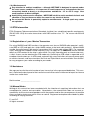
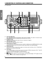
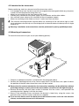
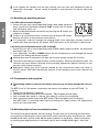
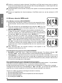
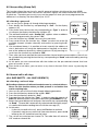
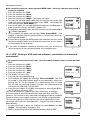
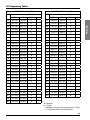
1
ABOVE ALL... SAFETY! .......................................................................................................... 3
1.1 Symbols used ................................................................................................................ 3
1.2 Warnings........................................................................................................................ 3
1.2.a General ................................................................................................................ 3
1.2.b Radiofrequency/installation ................................................................................. 3
1.2.c Automatic Transmitter Identification System (ATIS) ........................................... 3
1.2.d Environmental ...................................................................................................... 4
1.3 ETSI Information ............................................................................................................ 4
1.4 Registration of your Marine Transceiver ...................................................................... 4
1.5 Assistance ..................................................................................................................... 4
1.6 Manual Notes ................................................................................................................ 4
2
INTRODUCTION ..................................................................................................................... 5
2.1 Generalities .................................................................................................................... 5
3
DESCRIPTION OF CONTROLS AND CONNECTORS ......................................................... 6
3.1 Front panel .................................................................................................................... 6
3.2 Back panel (connections) .............................................................................................. 7
3.3 Microphone ................................................................................................................... 8
4
INSTALLATION ....................................................................................................................... 9
4.1 Contents of package ..................................................................................................... 9
4.2 Location for the transceiver ......................................................................................... 10
4.3 Mounting of transceiver ............................................................................................... 10
4.4 Adjustment of angle .................................................................................................... 11
4.5 Installation of the antenna/electromagnetic exposure ................................................ 11
4.6 Mounting of Microphone ............................................................................................. 12
4.7 Connections ................................................................................................................ 12
4.7.a Power Supply .................................................................................................... 13
4.7.b GPS device ........................................................................................................ 13
4.7.c Antenna ............................................................................................................. 13
5
BASIC OPERATION .............................................................................................................. 13
5.1 Turning NEPTUNE on/off ............................................................................................. 13
5.2 Volume regulation ........................................................................................................ 13
5.3 Squelch Regulation ..................................................................................................... 13
5.4 Selecting an operating channel ................................................................................... 14
5.4.a With alphanumerical keypad ............................................................................. 14
5.4.b Using the microphone buttons (UP or DOWN).................................................. 14
5.5 Transmission and reception......................................................................................... 14
5.6 Selecting high and low transmission power ................................................................ 14
5.7 Instant recall of channel 16 ......................................................................................... 15
5.8 Display lighting ............................................................................................................ 15
6
SCANNING FUNCTIONS ..................................................................................................... 16
6.1 Channel scanning ........................................................................................................ 16
6.2 Dual Watch and Triple Watch ...................................................................................... 16
6.3 Activation of Dual Watch/Triple ................................................................................... 17
6.4 Memory channels (MEM mode)................................................................................... 18
6.4.a Memory scanning (SCAN MEMORY) ............................................................... 18
6.4.b Reception/Transmission during SCAN MEMORY ............................................. 18
6.4.c To delete/To jump a pre-selected channel in memory ...................................... 18
1
ENGLISH
INDEX
USE WITH GPS ..................................................................................................................... 19
7.1 Function ....................................................................................................................... 19
7.2 GPS information on the display ................................................................................... 19
8
DIGITAL SELECTIVE CALLING (DSC)................................................................................. 19
8.1 Introduction ................................................................................................................. 19
8.2 Mobile Marine Identification Service (MMSI) ............................................................... 19
8.3 Navigating the DSC menu ........................................................................................... 20
8.4 Individual call (ROUTINE TO) ....................................................................................... 20
8.4.a Sending an individual call .................................................................................. 20
8.5 Group calling (Group Call) ........................................................................................... 21
8.5.a Sending a group call ......................................................................................... 21
8.6 General call to all ships (ALL SHIP SAFETY – ALL SHIP URGENCY) ........................ 21
8.6.a Sending a call to all ships.................................................................................. 21
8.7. DSC DISTRESS call..................................................................................................... 22
8.7.a Sending a DISTRESS call ................................................................................... 22
9
RECEIVING A DSC CALL ..................................................................................................... 23
9.1.a Receiving a distress call .................................................................................... 23
9.1.b General call to all ships...................................................................................... 23
9.1.c Individual call ..................................................................................................... 23
ENGLISH
7
10 CUSTOMIZATION ................................................................................................................. 24
10.1 Menu settings .............................................................................................................. 24
10.2 Navigation in the menu of settings .............................................................................. 24
10.3 List of settings ............................................................................................................. 24
10.4 “ Log” (list of registered calls) ...................................................................................... 24
10.5 “Dir” (Entries in the directory) ...................................................................................... 25
10.5.a Addition of addresses ...................................................................................... 25
10.5.b To modify/cancel addresses ............................................................................. 25
10.6 “Posn”(Setting of position coordinates and adjustment of UTC time) ........................ 25
10.7 ”LCD” (display contrast) .............................................................................................. 26
10.8 “Beep” (Enable/disable keypad beep) ......................................................................... 26
10.9 “ZONE”(Adjustment of UTC time deviation) ................................................................ 26
10.10 MMSI (Setting of personel MMSI code and MMSI group code) ................................. 26
10.11 “ATIS” (Setting of ATIS code and activation – deactivation
of automatical transmission) ....................................................................................... 27
11 PROGRAMMING AND SELECTION OF PRIVATE CHANNELS ......................................... 28
12 MAINTENANCE .................................................................................................................... 28
12.1 Maintenance and warnings ......................................................................................... 28
13 TROUBLESHOOTING .......................................................................................................... 29
14 TECHNICAL SPECIFICATIONS: .......................................................................................... 30
14.1 Transmitter ................................................................................................................... 30
14.2 Receiver ....................................................................................................................... 30
15 FREQUENCY TABLE ............................................................................................................ 31
2
1 ABOVE ALL... SAFETY!
1.1 Symbols used
Notes such as this one indicate practical advice that we suggest be followed for optimal
performance with NEPTUNE.
1.2 Warnings
1.2.a General
This device has been tested for compliance with Class D digital marine device limits.
These limits were created to allow for reasonable protection against damaging interference.
This device is to be used solely as an aid to navigation. Its settings may be influenced by
diverse factors, such as defects or malfunction of the device, environmental conditions
or improper use.
It is the user’s responsibility to observe reasonable prudence and judgement in navigation, and as such this device should not be considered a substitute for this reasonable
prudence and judgement.
Do not open the radio for any reason! NEPTUNE’s precision mechanics and electronics
require expertise and specialized equipment; for the same reason, the radio should under
no circumstances be realigned as it has already been calibrated for maximum performance. Unauthorized opening of the transceiver will nullify the warranty.
1.2.b Radiofrequency/installation
Midland recommends following the requirements for prevention of radiofrequency exposure. Unauthorized changes or modifications to this device may invalidate conformity
to the ETSI Regulations. All changes or modifications must be approved in writing by
MIDLAND Corp.
This VHF DSC transceiver generates and irradiates electromagnetic energy (EME) at radiofrequency (RF), and as such must be installed and placed in operating conditions that
are in conformity with the instructions contained in this manual and with current regulations. Not following these instructions can cause personal injury and/or malfunction of
the device.
Do not use NEPTUNE before connecting a suitable antenna that is in perfect working
condition – although NEPTUNE is protected, this may seriously damage the stages of
transmission power.
Do not use transmit before ensuring proper connection of the antenna. During transmission, remain at a minimum distance of 1mt from the antenna.
1.2.c Automatic Transmitter Identification System (ATIS)
Your marine transceiver may activate, if necessary, the ATIS function. The ATIS function
may be activated when using the transceiver within the internal navigable waters of Europe which require the automatic transmission of identification. For further details, please
contact your local authorities.
3
ENGLISH
For ease and convenience of viewing, NEPTUNE uses symbols to highlight urgent situations,
practical advice, and general information.
Warnings such as this, shown using an open hand symbol, indicate a crucial description
regarding technical repairs, dangerous conditions, safety warnings, advice and/or important information. Ignoring these symbols may result in serious problems and/or damage
and/or personal injury.
ENGLISH
1.2.d Environmental
Pay attention to ambient conditions – although NEPTUNE is designed to operate under
the most severe conditions, it is important to avoid exposure to environments that are
excessively humid or dusty, or to temperatures outside the –15 to +55°C range. Also
avoid exposure to direct sunlight.
Avoid jarring and excessive vibration – NEPTUNE is built to resist mechanical shock and
vibration as long as these are within the norm for any electrical device.
Do not use this device in potentially explosive environments. A single spark may cause
an explosion.
1.3 ETSI Information
ETSI (European Telecommunications Standards Institute) has established specific requirements
(EN 301 025-1/2/3) for marine transceivers with DSC function class ”D”. For use on non-SOLAS
vessels.
1.4 Registration of your Marine Transceiver
For using GMDSS and DSC functions, the operator must have a GMDSS radio operator’s certificate (SRC or LRC) and apply for a ships MMSI number at the local radio authority. Without MMSI
number the radio can only be used as conventional VHF marine radio without DSC. For seagoing
ships, entering the European inland waterways you can apply for an additional licence and can
obtain an ATIS number for the ship’s radio station. For ships, operating only on inland waterways,
a ship’s licence can be obtained for ATIS mode only. Switching to ATIS mode is requested on all
european inland waterways. In ATIS mode, automatically some restrictions of transmit power apply
on certain channels, and some functions like Dual and Triple Watch are not available. Your distributor may programm your radio according to your needs.
1.5 Assistance
We urge you to write the serial number of your transceiver in the space provided below. This number is found on the back panel of the transceiver and will be useful in the event of repair/assistance
and/or loss and/or theft.
Serial number _______________________
1.6 Manual Notes
Writing of this manual has been completed with the intention of supplying information that are
comprehensive, precise and up-to-date. Nevertheless, the manufacturer does not assume responsibility for the actual correspondence with the product and for the consequences of possible
errors caused by factors over which it has no control. Equipment and options described may differ
according to varying countries.
E. and O.E.
All rights reserved.
4
2 INTRODUCTION
Congratulations for choosing Midland’s marine transceiver NEPTUNE. This product is a high
performance, mobile VHF DSC marine transceiver. The following are its principle features:
• Equipped with all international channels available (correctly assigned).
• High transmission power of 25W, which allows the user to maintain contact from large distances, and a low transmission power of 1 watt to reduce consumption during short-distance
communication.
• Switchable between DSC System (Class “D”) and ATIS function for European inland waterways
• Principal commands duplicated on the microphone for faster accessibility – channel selection and channel 16 recall.
• Backlit LCD display and adjustable contrast – constantly shows NEPTUNE’s parameters and
settings and occurs a optimal visualization.
• Possibility to program 20 private channels and 16 MMSI numbers by means of the optional
programming kit “PGR NEPTUNE”. We remind that the use of private channels is controlled by
the national competent authorities: for this reason, we suggest you contact the local radio communication authorithies. For the use in Germany a special licence is requested. Only authorized
persons are allowed to use private channels when shipping on European inland waterways.
• Extraordinary capability for water resistance, conforms with the standard IP54.
• Recall button for Channel 16 – for instant access to channel 16 (the universal marine channel
for emergency contact).
• NMEA connection – use the interface cable supplied for easy connection from transceiver to
optional GPS system, such as GPS 200 or other compatible GPS. Once connected, the display
will show the automatically updated coordinates (latitude and longitude) and time data.
• DSC Digital Selective Calling – for security on the water and the ability to make quick calls
automatically (the transceiver supports DSC (Digital Selective Calling) operations with a specifically designed DSC unit which conforms to the ITU-R standard, M493-10 Class D requirement).
• ATIS-Function – Automatic Transmiiter Identification System for European inland waterways
• MMSI directory, which simplifies the sending of DSC calls to frequently called contacts and
allows viewing of contact name on the display.
• Mounting on adjustable bracket for stable and comfortable positioning in any condition.
• Connection to an external speaker (optional) – for listening to communications further away
from the transceiver.
The manufacturers, in their effort to constantly improve product quality, reserve the right to
change the above characteristics without forewarning. For eventual updates, visit www.cte.it or
contact your authorized dealer.
NEPTUNE is switchable between DSC System (Classe “D”) and ATIS-Function for European
inland waterways and is approved for both systems.
In ATIS mode, all Scan and Dual / Triple Watch functions are disabled, and on all shipto-ship and ship-to harbor channels the transmit power will automatically be reduced to
values between 0.5 and 1 Watt.
5
ENGLISH
2.1 Generalities
3 DESCRIPTION OF CONTROLS AND CONNECTORS
3.1 Front panel
�
�
�
�
�
�
��
ENGLISH
��
�
(1)
(2)
(3)
(4)
(5)
(6)
(7)
6
�
�
��
OFF/VOLUME knob
Turns NEPTUNE on/off and regulates audio volume reception. The radio is turned off when
you completely rotate the knob counter-clockwise until it clicks.
SQUELCH knob
Regulates the squelch level (noise silencer in absence of signals).
MICROPHONE socket
Insert the mike connector into this socket.
Alphanumerical keypad
The keypad gives the possibility to select channels, to add your own MMSI identification code
and to activate/deactivate many other functions described in the following pages.
FUNCTION keys
They enable to enter into the menu pages, to activate some functions such as Triple Watch,
SCAN or to activate the ATIS mode.
H/L button
Push the H/L button to select high transmission power (25W) or low power (1W). The LCD
display will show HI (high power) or LO (low power).
The H/L function is accessible in normal VHF or MEM mode.
button
Hold the
button down to activate the display and keypad backlight (“LITE” appears on the
display). You can select 4 different backlight levels.
D/W button
This button activates the Dual Watch function, able to search alternatively the tuned channel
and channel 16.
(9) Button 16
Pressing the 16 button provides quick access to channel 16.
(10) DISTRESS button
The button below a soft cover sends a DISTRESS call for help. The signal also includes your
MMSI identification code and the nature of the distress. If a GPS is connected to the device,
data regarding position and time are also included in the call. For further details, see paragraph 8.7.
The Distress function, or any other DSC transmission function, is not operative until a MMSI
user code has been inserted.
(11) LCD Display
The large LCD (liquid crystal) display constantly shows the operating status of the device as
well as being a function guide thanks to its easily readable dot matrix area.
(12) Internal speaker
Guarantees clear listening of communications.
3.2 Back panel (connections)
Warning! Faulty connections or short-circuits may seriously damage NEPTUNE. Before
attempting any connections, consult the specialized sections of this manual.
�
�
(1)
(2)
(3)
(4)
�
�
Antenna socket
This SO 239 socket is for connecting an appropriate antenna.
Power cable
This red/black cable has to be connected to a power source of 12 Vdc (red is positive). Attention: for 24 V power sources a converter is needed!
Socket for additional external loudspeaker
You can use this jack for the connection to a suitable external loudspeaker (optional), if needed.
GPS connector
Allows for connection to the optional receiver module “GPS200” cod. C723 (or other compatible receiver), for obtaining, viewing and transmitting (with DSC) information regarding position
and current time data.
7
ENGLISH
(8)
3.3 Microphone
(1)
(2)
ENGLISH
(3)
(4)
UP and DOWN buttons
These two buttons change the tuning channel. The first
scrolls upwards through the tuned marine channels, the
second scrolls downwards.
Button 16
For ease of use, button 16 performs the same function
as the button 16 on the front panel of the transceiver.
PTT (push to talk)
Pressing this button will begin transmission.
Microphone
During transmission, speak a few centimeters from the
microphone.
�
�
�
�
8
4 INSTALLATION
ENGLISH
4.1 Contents of package
Before using your transceiver, ensure that your package is complete and contains:
(1) Mounting bracket
(2) DC power cord with integrated protecting fuse
(3) Knobs (2 pieces)
(4) Mounting piece for microphone
(5) Self-threading screws for mounting bracket (4 pieces)
(6) Screws for mounting bracket (4 pieces)
(7) Washers (4 pieces)
(8) Grained washers (4 pieces)
(9) Nuts (4 pieces)
(10) Self-threading screws for microphone mount (2 pieces)
(11) Screws for the microphone mount (2 pieces)
(12) Washers (2 pieces)
(13) Grained washers (2 pieces)
(14) Nuts (2 pieces)
(15) Certificate of warranty and instruction manual (not shown)
Depending on the model, some parts may already be attached/connected to the device. In any
case, if any parts are missing, immediately contact your supplier.
9
ENGLISH
4.2 Location for the transceiver
Before continuing, look for a place to install the transceiver which:
• Is far enough away from any device sensitive to magnetic/electromagnetic fields (e.g. compass)
in order to avoid interference during their use.
• Allows for accessibility to the front panel of NEPTUNE.
• Provides easy connection to a power supply, for the antenna and for other cables.
• Has sufficient space close by for installation of the microphone support.
• Allows for mounting of the antenna at least 1 meter from the transceiver.
The universal mounting bracket supplied allows for mounting of the transceiver high up (with
the bracket above the device) or on the bridge (with the bracket below the device) with an angle
range of 45°.
Warning! Installation and connections must be performed in part by qualified persons.
4.3 Mounting of transceiver
To mount the transceiver to your vessel (see following picture):
1. Choose an appropriate location, as explained in the paragraph above.
2. Position the mounting bracket on the surface upon which it will be fixed, use a pencil to draw
the position of the four holes where the screws will be inserted.
Ensure that the surface intended for the transceiver mounting can be drilled into without
provoking damage to other parts of the vessel and be careful to not drill right through it.
3. Remove the bracket, drill four holes smaller in diameter than the screws, and reposition the
mounting bracket, aligning it with the four holes.
4. Screw in the mounting screws and ensure the bracket is fixed firmly, using the screws, the
grained washers, the flat washers and the nuts supplied.
If you are not able to reach the back part of the bracket surface to fix the nuts onto the
screws, use threaded screws to fix the bracket.
10
4.4 Adjustment of angle
To change the angle of inclination after installation:
1. Loosen the mounting knobs on the sides of the bracket.
2. Adjust the transceiver to a better angle, lining up the holes of the internal part of the bracket
with those on both sides of the transceiver.
3. Tighten the knobs to fix the transceiver into place.
4.5 Installation of the antenna/electromagnetic exposure
For optimal radio settings and minimal user exposure to electromagnetic radiofrequency energy,
ensure that:
• The antenna is connected to the transceiver and is properly installed.
• The antenna is situated away from people and is positioned at least one meter from the transceiver and microphone.
• The connector is a standard PL259 (male UHF).
11
ENGLISH
5. Tighten the screws with a screwdriver so that the bracket is firmly fixed to the surface.
6. Align the transceiver on the bracket, ensuring the holes of the internal part of the bracket line up
with those on both sides of the transceiver (you can choose the preferred notch in order to best
adjust the angle of the transceiver’s front panel for ease of viewing and use (15° of variation for
each notch).
7. Mount the mounting knobs on the two sides of the bracket to soundly fix the transceiver.
Keep the transceiver and microphone at a distance of at least 1 meter from all other magnetic devices (e.g. compass) on your vessel.
4.6 Mounting of Microphone
ENGLISH
To mount the microphone mount, look first for a mounting point
close to the transceiver. The distance between the transceiver
and the wall mount must be less than the length of the microphone cable.
Do not pull excessively on the microphone cord. This part
is important to the correct function of the device: over
time, pulling may damage the cord and impede the user
from transmitting.
4.7 Connections
Refer to the following diagram:
����
���
�����
����������������
������
����������
�����������
�������
������������
������������
12
4.7.a Power Supply
The transceiver power supply must be 12Vdc (see specifics in par. 14). The red cable must be
connected to the positive pin, the black to the negative pin.
Warning! A faulty connection may seriously damage the radio!!
4.7.b GPS device
If your NEPTUNE transceiver is connected to a GPS resceiver, such as the GPS 200, you can
obtain and view NMEA information relative to the current position the vessel (latitude and longitude) and the local time with respect to Greenwich Mean Time (GMT).
4.7.c Antenna
The antenna is an extremely important part of the device and noticeably influences the settings
of any telecommunications device. Contact your supplier regarding the antenna and request
advice about how to mount and best connect it to your transceiver.
Warning! Ensure the antenna is in perfect working order. It may otherwise seriously
damage the radio! A periodical measurement of the stationary waves is advised using a
suitable SWR metre.
5 BASIC OPERATION
5.1 Turning NEPTUNE on/off
To turn the transceiver on, rotate the OFF/VOLUME knob clockwise until it clicks on. You will
hear a beep (acoustic signal) and the LCD display will come on: the device is turned on to VHF
mode.
To turn the transceiver off, rotate the knob counter-clockwise until you hear further click: the LCD
display will turn off.
If your transceiver is not connected to a GPS resceiver, it is necessary to insert manually your
coordinates, otherwise an alarm will continue to sound. For further details, see par.7.1.
5.2 Volume regulation
Bring the OFF/VOLUME knob first to medium volume. Once the transceiver picks up a signal,
adjust the volume to a comfortable level. If no signal is picked up, use the squelch control as
described in the following paragraph and regulate the volume using background noise.
5.3 Squelch Regulation
Squelch is used to eliminate the annoying background noise you hear when no signal is being
picked up. If the squelch is adjusted correctly, there should be silence in between calls as well
as a reduction in battery consumption. To regulate squelch:
1. Rotate the SQ knob completely counter-clockwise until you hear background noise (if you don’t
hear anything, turn up the volume) and bring up RX on the LCD display.
2. If no signal is being received (only noise), slowly rotate the SQ knob clockwise, stopping as
soon as the noise and RX disappear stably.
13
ENGLISH
The power cable is equipped with a protection fuse. If the fuse shorts, look for its reason
before substituting the cable with a new one of the same type and value. Never shortcircuit it, as this may damage the radio.
If you regulate the squelch level too high (closed), you may hear only background noise or
intermittent discharges. Correct setting of squelch is also important for reasons discussed
further on.
ENGLISH
5.4 Selecting an operating channel
5.4.a With alphanumerical keypad
1. Ensure that you are in normal operating mode (radio mode), otherwise
press several times the button related to “RAD” or press the “C” button
until the display shows: (A)
2. Select the desired channel and confirm by pressing the “E” button; the
radio emits 4 beeps.
If there is no confirmation within 2 seconds by pressing the “E” button,
Neptune will return to the previously used channel.
A
If a “notexistant” channel is inserted, for example CH99, or the radio does not beep 4 times for
confirmation after pressing the “E”-button, NEPTUNE returns to the previously used channel.
5.4.b Using the microphone buttons (UP or DOWN)
1. Ensure that you are in normal operating mode (Radio mode); otherwise follow the procedure
described in par. 5.4.a.
2. Press repeatedly the UP or DOWN buttons on the microphone to scroll through the marine
channels until finding the desired channel.
Holding down one of the buttons will allow you to scroll quickly through the channels.
The marine band does not recognize some channel numbers. Refer to the frequency table. The
channels may have different receiving and transmitting frequencies (duplex channels) or may
have the same (simplex channels).
Regulations require that some channels operate on low transmission power (see Chap.1).
For this reason, NEPTUNE automatically switches to low frequency when these channels are
selected.
5.5 Transmission and reception
Transmitting without a perfectly functioning antenna may seriously damage the transceiver.
The PTT (Push-To-Talk) button is located on the external microphone of your NEPTUNE. To
transmit:
1. Ensure that no one else is speaking.
2. Hold down the PTT button on the microphone. TX will appear on the Diplay.
3. Wait a second, then speak in a normal voice about 5 cm from the microphone.
4. When you have finished, release the PTT button: TX will disappear from the display.
Now NEPTUNE is in receiving mode (silent and waiting for a signal) where it will automatically
receive any communication.
5.6 Selecting high and low transmission power
The transmission phase absorbs the most energy. To reduce the risk of wearing out the battery,
we recommend selecting low transmission power when transmitting over short distances. Hold
the H/L button down (on the radio): Lo (low power) appears on the display. When transmitting
or receiving over long distances or with weak signals, press the H/L button again. Lo will be
14
replaced with Hi (high power) on the display.
When the transceiver is tuned to a channel limited to low output power, pressing the H/L button
has no effect.
Channel 16 is a security and distress channel. This channel is used to establish initial contact
with another station and for emergency communication. This channel can be called up at any
time by pressing button 16 on both the transceiver. To return to normal operations, select
another channel using the alphanumerical keypad or the UP/DOWN buttons on the microphone.
By pressing a second time the 16 button, the radio returns to the previously used channel before
selecting channel 16.
Do not transmit on channel 16 unless absolutely necessary. Doing so may impede emergency operations.
5.8 Display lighting
If ambient lighting is insufficient for reading the display, the LCD display backlighting can be
adjusted. Hold pressed the button
until a desired level is reached or until it has been completely turned off. If the backlighting is activated, the display shows “LITE”.
The chosen level of backlighting remains stored, also in case of extinction and successive
turning on the radio.
If you desire to switch off the backlighting immediately or if you like to reactivate the previously
inserted level, press the
button.
15
ENGLISH
5.7 Instant recall of channel 16
6 SCANNING FUNCTIONS
ENGLISH
6.1 Channel scanning
NEPTUNE can automatically search for signals throughout the marine
band by scanning, or selecting the channels in rapid sequence. When
a signal is detected, the scanning pauses on that channel and remains
blocked until the signal ends. Before the scanning automatically starts
again, NEPTUNE waits for a few seconds in case the user wishes, if
necessary, to respond to a call even if in truth you will see the channels
being scanned.
B
The NEPTUNE scanning happens with a minimum of 2 channels to a
maximum of 56 channels on the INT band (channel 70 is not selectable).
• In order to execute the scanning of the marine channels, it is necessary
to create a list of channels for scanning. Operate in the following way:
1. Select a channel you desire to insert into the the scanning list.
2. Hold pressed for 2 seconds the function key corresponding to the word
“SCAN” (B); the radio beeps twice and on the display appears for a
short moment the indication “Scan Ena” (C).
C
3. If you desire to cancel a channel from the scanning list, repeat the procedure as described at point 2. In that case the display is showing
“Scan Inn”.
4. Once created your list, you can activate the scanning by pressing the
function key corresponding to the word “Scan” (B).
• If you want to eliminate (useful if there are distortions) or to exclude momentarily (useful for undesired conversations) a channel during scanning, operate as follows:
D
• DEFINITIVE EXCLUSION OF A CHANNEL:
If your NEPTUNE is operating on a disturbed channel, press the function key correponding to the word “Inn” (E) .
• MOMENTARILY EXCLUSION OF A CHANNEL:
Press the function key corresponding to the indication “Adv” to advance the scanning and to eliminate definitivly this channel from the scanning list. At the end of the complete scanning cycle, the channel previously jumped will be monitored again.
E
• The scanning can be stopped by pressing the buttons C, or button
16 on the microphone or by sending out a DISTRESS call. Your transceiver will stop on the current channel (if you pressed button C) or on
channel 16 (if you pressed 16 or PTT on the microphone).
Note: Scanning does not function correctly if the squelch is not regulated as described in
par.5.3.
All scan modes are not enabled during ATIS mode (this is requested by authorieties) on inland
waterways.
6.2 Dual Watch and Triple Watch
The meaning of these terms are:
• Dual Watch – allows the user to remain tuned to a channel of choice while periodically performing an automatic verification of signals on channel 16.
• Triple Watch – as written above, including a third channel chosen by the user.
16
To activate Dual or Triple watch:
• Dual watch - Select a desired channel and press the D/W-button. The Display will indicate
“D/W” and you will see the two monitored channels.
The Dual Watch function can be stopped in 5 different modes: by pressing the PTT- or the “16”
buttons on the microphone, “D/W”- or “C”-buttons or by sending out a DSC-call.
• Triple watch – select one of the 2 channels you desire to monitor together with channel 16. Hold pressed the function key corresponding
to the written T/W until you hear two beeps. Now on the display appears the indication “User”.(F). Move now to the second channel you
desire to monitor, press the function key corresponding to the indication T/W. Now you will see all three channels sliding on the display with
indication T/W. “Adv” appears too, that, similar to SCAN function, has
the aim to exclude momentarily the monitoring of the current channel.
The Triple Watch function can be stopped by pressing the C-button,
F
the PTT- or the 16-buttons or by sending out a DSC call.
For both modes, the operation can be reassumed with the following
diagram:
17
ENGLISH
6.3 Activation of Dual Watch/Triple
Similar to scanning of marine channels, Dual Watch and Triple watch arrest when a signal is
found and remain blocked for a few seconds after the signal disappears, in order to give the user
a chance to respond to a call, if necessary.
Dual/Triple Watch cannot function correctly if the squelch is not correctly regulated, as described
in par .5.3.
ENGLISH
Because of regulations for inland waterways, Dual/Triple watch can not be activated in ATIS
mode.
6.4 Memory channels (MEM mode)
6.4.a Memory scanning (SCAN MEMORY)
1. Similar to the scan function, memory scan will cycle sequentially through the channels, but only those, which have been pre-selected (at least
3).
2. Press the function key corresponding to the indication “M/S” (G). The
radio emits 2 beeps and on the display appears for ca. 2 seconds the
indication “M/S Sel” (H).
3. Select another channel and repeat the procedure mentioned above.
In order to eliminate a channel erroneously inserted into scan cycle,
select the channel, press and hold the function key corresponding to
the indication “M/S” until the display shows “M/S Del” (I)
4. Once all channels are stored, the scanning can begin (SCAN MEMORY): Press the function key corresponding to the indication “M/S”.
The channels will be monitored and the display will show the indication
“M/S” – which indicates the scanning of the stored channels, - “Adv”
and “Del” in relation to the 2 function keys. Every time a signal/disturb
is found on a channel, the scanning stopps for a few seconds in order
to give the user a chance to respond to the call or to cancel the channel, if necessary.
Note: Scanning does not function correctly if the squelch is not
regulated as described in par. 5.3.
G
H
I
6.4.b Reception/Transmission during SCAN MEMORY
• Reception: If NEPTUNE finds a signal the scanning interrupts. The display indicates “RX”
instead of “M/S” and the communication will be received through the loudspeaker.
• Transmission: It is possible to transmit at any time, also when the scanning is active. In that
case NEPTUNE will always transmit on channel 16; if instead the transmission is done after a
signal has been found, the device will transmit on the previously busy channel. After the transmission the scanning comes interrupted.
6.4.c To delete/To jump a pre-selected channel in memory
If during the scanning a signal is received on an undesired or disturbed channel, it is possible to
cancel the channel in a definitive way or to jump the channel momentarily.
In order to execute these functions, the radio must be syntonized on a channel (firm scanning).
Through the two function keys corresponding to “Adv” and “Del” you will have the possibility to
jump the busy channel respective to cancel it from the pre-selected list of channels.
There are 4 modes to stop the scanning of channels in memory:
1. By pressing the PTT-button.
2. By pressing the 16 button on the microphone or on the front panel
3. By pressing the C-button.
4. By sending out a DSC-Call.
18
7 USE WITH GPS
7.1 Function
ENGLISH
If connected to a GPS receiver (GPS200), the transceiver will display the vessel position (latitude
and longitude), as well as time data. If information regarding position data are not received, in
the normal radio mode, time data does not appear and a minute-long warning tone will sound
(can be deactivated by pressing any button). This tone will sound every 4 hours, reminding the
user that position data needs to be inserted. The user may also insert the coordinates manually
as described in par. 10.6.
7.2 GPS information on the display
Refer to the following illustrations:
1
2
1. Position indicator
Displays GPS or manually-inserted coordinates.
2. Time indicator
Shows data supplied by the GPS or the transceiver’s clock.
8 DIGITAL SELECTIVE CALLING (DSC)
8.1 Introduction
Digital Selective Calling is a semiautomatic method for controlling VHF, MF and HF radio calls.
It was also designed as part of the global marine security and emergency response system
(GMDSS). It is likely that DSC will eventually replace audio calls on emergency frequencies and
will be used to send urgent and routine radio-transmitted maritime security information. This new
service will allow crafts to send/receive calls of an emergency, urgent, security, or routine nature
to/from vessels equipped with a DSC transceiver.
To avoid accidentally sending a distress call or a call sent incorrectly, contact your vendor
or local authorities for updates on DSC operating and emergency procedures.
In European inland waterways DSC-function is not allowed.
8.2 Mobile Marine Identification Service (MMSI)
Important! To send/receive DSC calls, the user must program his personal MMSI code into the
transceiver. This is a nine-digit number used by marine transceivers equipped for DSC digital
selective calling. This number is used much like a telephone number for contacting other,
specific vessels. For further details on programming your MMSI, see par. 10.10.
19
8.3 Navigating the DSC menu
ENGLISH
NEPTUNE offers many DSC functions. For this reason it was created a specific menu of settings
and activations accessible via the function keys as follows:
1. Access the “CALL”-Menu by pressing the related function key.
2. Press the function key corresponding to the word “Type” to select the type of desired call.
Once inside a sub-menu, you can return at any time to the main menu by pressing the C-button
and terminating the current operation.
8.4 Individual call (ROUTINE TO)
The user can carry out an individual call to a specific DSC station (a vessel or a costal station).
To carry out calls, you have to enter the MMSI code manually or recall it from the preprogramed
MMSI directory. For further details on programming the MMSI directory, see par. 10.5.
8.4.a Sending an individual call
You can carry out an individual call using the following procedure:
1. Press briefly the function key corresponding to CALL. On the display appears (J):
2. The outlined line below under “To Routine” appears if no owner name was
inserted in the column “Dir”, otherwise a similar situation may appear (K):
3. Press the function key “Ch 06” to access the sub-menu.
J
4. Press several times the function key “Chan” in order to select one of
the 23 available channels (simplex channels) and confirm by pressing
the E-button.
����
5. Like mentioned above, it is possible, to insert manually the address you
desire to call (using the alphanumerical keypad), or to select one of the
addresses previously stored (maximum 16) by pressing several times
the function key related to the word “DIR”.
K
6. Then, after you have selected the communication channel and the address, the call can be carried out by pressing the function key corresponding to “Send” and confirmed by pressing the E-button.
7. After the call execution the radio operates as follows:
- If you have carried out a call to a ship, after the call you will get an answer, the radio will move
to the channel previously selected under step 3-4.
8. At this point:
- If the call comes confirmed from the other part, the display shows
the message: (L). In this case the answer is reached from ship
100000000 and the possible communication channel will be CH06.
To confirm the reception of the received message, NEPTUNE will
emit an acoustic message that can be interrupted by pressing the
function key corresponding to ”OK” or “STOP”.
Pressing OK beyond interrupting the acoustic signalling, NEPTUNE
is syntonized on the communication channel (in our example 06).
If no function key comes pressed at that time (1 minute) the acoustic
L
message will extinguish automatically.
- If the call does not come comfirmed, the display will indicate (M), by
pressing the function key correponding to “Stop” the radio will return
to the normal radio mode.
Once inside a sub-menu, you can return at any time to the main individual
CALL-menu (Routine to) by pressing the C-button and terminating the
current operation.
M
20
8.5 Group calling (Group Call)
8.5.a Sending a group call
You can carry out a group call through following procedure:
1. Press breafly the function key correponding to “Call”. On the display
appears: (N)
2. Press three times the function key correponding to “Type” in order to
visualize on the display the following situation: (O)
3. The outlined line below under “Group Call” appears when no address
N
has been programmed in the column “Dir”.
4. Press the function key “Ch 06” to access the sub-menu.
5. Press several times the function key “Chan” to select one of the 23
available channels (simplex channels) and confirm by pressing the Ebutton.
6. Like mentioned above, it is possible to insert manually the address of
who is desired to call (using the alphanumerical keypad), or to select
one of the addresses previously stored (maximum 16) by pressing seO
veral times the function key related to “DIR”.
7. Then, after you have selected the communication channel and the owner address, the call can
be carried out by pressing the function key corresponding to “Send” and confirmed by pressing
the E-button.
8. At this point you can communicate with the stations on the pre-selected channel that have
given an answer to you.
Once inside a sub-menu, you can return at any time to the main CALL-menu by pressing the
C-button.
8.6 General call to all ships
(ALL SHIP SAFETY – ALL SHIP URGENCY)
8.6.a Sending a call to all ships
Sending a distress call without founded reason is a criminal offence.
Never use this function unless you find yourself in a situation that
merits requiring help.
1. You can carry out a call to all ships through following procedure:
2. Press the function key related to the written “DSC”.
3. Press the function key related to “Call”.
4. Press one time the function key “Type” in order to select the type of call
SAFETY, otherwise press two times to select the type URGENCY (P-Q).
5. Select the type of desired call and press the function key corresponding
to “Send”. Channel 16 is automatically selected and the display requests confirmation before sending the call with the message: (R)
6. At this point:
- If you wish to confirm the call, press the E-button to continue.
- If you don’t want to carry out the call ( because of errors), press the 16
button or the “C”-button to leave the menu.
7. The call will be carried out on channel 70. The radio then will return to
VHF mode on channel 16.
P
Q
R
21
ENGLISH
This function allows the user to call a specific group of stations which have the same MMSI
group code memorized in their transceivers and which signals the audio channel the user wishes
to speak on. Therefore you can only carry out the group call when you have programmed the
addresses in a directory like described in par. 10.10.
During this procedure you are able to return to the main CALL-menu by pressing the Cbutton.
ENGLISH
8.7. DSC DISTRESS call
8.7.a Sending a DISTRESS call
IMPORTANT! You can only send a DSC call if you have been assigned an individual MMSI code
and this code has been programmed into the transceiver (otherwise the following commands
will be deactivated). For this operation, see par. 10.10.
Sending a distress call without founded reason is a criminal offence. Never use this function unless you find yourself in a situation that merits asking for help.
You can carry out the distress call through the following procedure:
1. Open the DISTRESS cover by pushing it to the right and hold it open.
2. Press momentarily the DISTRESS-button below. The display shows: (S)
3. Press the function key corresponding to “Undefined” in order to select the nature of the call (the pre-selection is UNDEFINED):
A. UNDEFINED
B. ABANDONING
S
C. PIRACY
D. M.O.B. (man over board)
E. FIRE
F. FLOODING
G. COLLISION
H. GROUNDING
I. LISTING
L. SINKING
M. ADRIFT
4. To send out the distress call hold down the DISTRESS-button for 5
seconds. An acoustic alert will emit and the distress call will be carried
out on channel 70 even when the channel is in use.
5. After the distress call, the transceiver will simultaneously check channel 70 and channel 16 on a receipt of DSC confirmation and meanwhile
T
appears following: (T)
6. At this point:
- If the distress call is received and confirmed by another DSC radio station, the acoustic
alarm will stop sounding and the display will return to normal use in VHF mode on channel
16, sending on high transmission power.
- If no confirmation is received, the device will re-send the distress call at intermissions of 3.5
– 4.5 minutes (even with channel 70 in use), until a confirmation is received or until the user
manually cancels the call through the C-button.
Pressing button 16, the transceiver will return to normal VHF operation, but the call will
not be cancelled and the person who responded to the call may not have called off rescue
operations.
If, at step 4, the user stops pressing the DISTRESS button before 5 seconds have elapsed, the
distress call will not be sent. To exit and return to VHF mode, press button 16.
The acoustic alarm will only stop definitively once the transceiver has received confirmation
from the receiver of the call.
It is possible to arrest the acoustic alarm by pressing the button C or 16.
22
9 Receiving a DSC call
When the user receives a DSC call, the transceiver will automatically respond according to the
type of call.
Information shown on the LCD display will vary according to the type of call. Refer to the diagram below for several examples:
GENERAL CALL
TO ALL VESSELS
INDIVIDUAL CALL
ENGLISH
DISTRESS CALL
9.1.a Receiving a distress call
When the transceiver receives a distress call, an acoustic alarm will sound. The pressure to the
function key “STOP” will deactivate the alarm.
When the signal also includes position and time data, these informations will appear on the
display. If no position and time data are included in the signal, the display will indicate 99°99
999°99 88:88.
9.1.b General call to all ships
When the transceiver receives a general call related to all vessels, it automatically moves to the
communication channel and emits an acoustic emergency alarm. The pressure of the function
key “STOP” will deactivate the alarm.
9.1.c Individual call
When the transceiver receives an individual call, it automatically moves to the channel indicated
by the DSC signal and emits a tone to alert the user of an incoming call. The pressure of the
function key “STOP” will deactivate the alarm.
The MMSI owner code contained in the signal appears on the display. If the MMSI owner code
has been programmed previously with name in the directory, the name of the caller appears too.
Every time NEPTUNE receives a call (distress, individual or general) an entry will be stored in the
list of registered calls “LOG”.
23
10 CUSTOMIZATION
10.1 Menu settings
NEPTUNE can carry out a series of settings in order to personalize the transceiver to your requirements and to insert the necessary data to its operation.
ENGLISH
10.2 Navigation in the menu of settings
To access the menu of setting use the functions keys.
All programmed settings are stored in non-volatile memory.
10.3 List of settings
Following find the possible settings:
Menu Items
Description
Par.
Log
Call directory of stored DSC calls type individual or distress calls.
10.4
Dir
Directory of MMSI owner names, MMSI codes and their details.
10.5
Posn
Manual programming of coordinates and the UTC time setting
(in the absence of GPS).
10.6
LCD
Display contrast adjustment.
10.7
Beep
Adjustment of keypad beep
10.8
ZONE
Local and UTC time deviation settings.
10.9
MMSI
Entry of your individual MMSI code and you MMSI group code.
10.10
ATIS
Entry of your indiviual ATIS code (for navigation in inland waterways) and switching on/off the automatical transmission of
the signal
10.11
10.4 “ Log” (list of registered calls)
With this menu you can consult a directory of the latest registered calls, in analogous way to the
registers of calls on a cellular phone.
1. Press the function key “DSC”.
2. Press the buttons “DSC” and “Log”. It will be shown the latest registered message.
3. By pressing the function key corresponding to “Back” all the other registered messages will be
shown.
4. Using the function keys corresponding to the symbol “ ” you will get some more informations:
coordinates and time.
24
You can insert into the directory the MMSI codes from frequently called stations, by giving them
a name (e.g. vessel or owner). Then you can search and use them more comfortably. When
receiving a call, MMSI owner name and MMSI code will be displayed.
1. Press the function key “Menu”.
2. Press the function key “More”.
3. Press the function key “Dir”.
4. At this point you enter to the directory pages. If no MMSI owner address was stored, the display will show “Entry”, throughout it has been
stored one or two MMSI owner addresses, the type of indication will
appear as follows:
5. By pressing the function key “Add” you will have the possibility to add
further MMSI addresses. By pressing the function key “VIEW” you will
have the possibility to modifiy/cancel the address shown on the display.
U
10.5.a Addition of addresses
1. Press the function key “Add”.
2. With the alphanumerical keypad (the keys are associated with letters like on a cellular phone)
you are able to write the name you want to associate with the MMSI code (f.e. TOM), then press
the E-button to confirm.
3. After the pressure to the E-button, on the display appears th cursor in
correspondence to “MMSI”
Write the identification code using the alphanumerical keypad (obligatorily 9 digits)
4. Press the E-button to confirm.
V
10.5.b To modify/cancel addresses
1. Press the function key “View”.
2. Select with the function keys “Next “ or “Back” the address you desire to modify/cancel.
3. Press the function key “Edit”.
4. If you desire to change the name or the code, press one of the 2 function keys associated to the name or the MMSI code “ ”.
5. If it is desired to eliminate completely the directory, press the function key “Del” and confirm by pressing subsequently the function key
“Yes”.
If it is desired to cancel the operation, press the function key “NO”.
It is possible to memorize max. 16 addresses. If the directory is filled up,
W
on the display will appear the indication “Full” and it will not be possible
to add further addresses. In this case it is necessary to cancel some.
10.6 “Posn”(Setting of position coordinates and adjustment of UTC time)
1.
2.
3.
4.
Press the function key “DSC”.
Press the key “Menu”.
Press the key “Posn”.
To insert the coordinates press the function key “Posn” and through the alphanumerical keypad
set up the coordinates.
5. Confirm by pressing the E-button. If “nonexistent” coordinates have been inserted, Neptune
will emit a double error beep rendering necessary the re-insertion.
6. In order to set the time, press the function key corresponding to “UTC” and confirm through
the E-button the executed operation. An eventual error message will indicate the wrong entry
of time data.
25
ENGLISH
10.5 “Dir” (Entries in the directory)
The insertion of time coordinates is obligatory to carry out DSC calls. If Neptune is connected to
a compatible GPS resceiver (GPS 200) the setting of these data is not compulsory.
ENGLISH
10.7 ”LCD” (display contrast)
The user can adjust the display contract to optimise visibility according to ambient conditions.
1. Press the function key “DSC”.
2. Press the function key “Menu”.
3. Press the function key “LCD”.
4. Using the function keys corresponding to “ ” ; “ ” you can increase the contrast of the display.
5. Confirm by using one of the following buttons: C , 16, function key DSC, or the PTT.
This setting remains stored on the Eeprom, therefore NEPTUNE will maintain the same settings
when the radio is turned on again.
10.8 “Beep” (Enable/disable keypad beep)
In order to activate or to inhibit the beep to the pressure of the keys operate as follows:
1. Press the function key “DSC”.
2. Press the function key “Menu”.
3. Press the function key “More”.
4. Press the function key “ More”.
5. Pressing the function key “Beep” activates or disables the acoustic message to the pressure of
the keys.
This setting remains stored on the Eeprom, therefore NEPTUNE will maintain the same settings
when the radio is turned on again.
10.9 “ZONE” (Adjustment of UTC time deviation)
The user can program the time deviation with respect to the UTC time so the transceiver’s display will show the time for the current time zone.
1. Press the function key “DSC”.
2. Press the function key “Menu”.
3. Press the function key “More”.
4. Press the function key “More”.
5. Press the function key “Zone”.
6. The display will show (X)
7. Pressing the function keys +, or –, will set the desired deviation.
X
8. Acting with the function key will activate or eliminate the visualization
of the time data on the display.
9. Confirm by pressing one of the following buttons: C , 16, function key DSC, or PTT.
This setting remains stored on the Eeprom, therefore NEPTUNE will maintain the same settings
when the radio is turned on again.
10.10 MMSI (Setting of personel MMSI code and MMSI group code)
This function allows the user to insert their personal MMSI identification code assigned by an
26
If you have accidentally inserted an incorrect code, you will have to
return the device to your approved vendor for a complete reset.
Z
10.11 “ATIS” (Setting of ATIS code and activation - deactivation of automatical
transmission)
Be careful to insert the correct code. Once the code has been saved, it cannot be modified.
1. Press the function key “DSC”.
2. Press the function key “Menu”.
3. Press the function key “More”.
4. Press the function key “ More”.
5. Press the function key “Atis”.
6. The display will show: (AA)
7. Press the key corresponding to .
8. On the display will appear the message “Enter atis MMSI”. The ATIS
AA
ID number is a ten-digit number (given by the authorities), always beginning with “9”. The first number “9” is stored already, thus it is need
only to enter the following 9 digits. Example: You received from the
authorities the ATIS code 9 211015923.
9. Insert the last 9 digits 211015923 and confirm by pressing the E-button. The display will show: (AB)
Your marine transceiver is able to activate, if necessary, an automatic transmission of your ATIS identification code each time the PTT is
AB
released. This function is only used when navigating in internal navigable
European waters which require automatic transmission of identification.
The user can request an ATIS code from the same organization in their
community which licenses radio operators. Program the code as described previously.
1. In order to activate it, press the function key correspondent to “Atis
disable”. On the display will appear: (AC)
2. Confirm by pressing one of the following buttons: 16, C or PTT.
AC
27
ENGLISH
appropriate authority.
Be careful to insert the correct personal MMSI code. Once the code has been saved, it
cannot be modified.
1. Press the function key “DSC”.
2. Press the function key “Menu”.
3. Press the function key “More”.
4. Press the function key “MMSI”. The display will show:
5. To insert the personal MMSI code press the function key to the right
under the arrow corresponding to the script “DSC”. The display will
show the message “Enter MMSI” (Y)
6. Insert the 9 digits, for example 900000000 and press the E-button in
order to confirm, now on the display appears: (Z)
Y
7. To programm the MMSI code, press the function key corresponding to
“ ” situated right below.
8. On the display will appear the message “Enter Group MMSI”, now
program 8 numbers (the first fixed number is 0 (zero)) and confirm by
pressing the E-button.
It is possible to change the MMSI group code whenever you want, while
the personal MMSI code can be inserted only one time; for this reason,
we recommend to pay attention.
3. When the ATIS function is activated, “ATIS” will appear on the upper part of the display.
If regulations in your community do not allow you programming the ATIS code by yourself,
contact your approved vendor for programming.
Activate the ATIS code only when requested by the proper authorities.
We remember that when the ATIS function is activated, DSC call are disabled.
ENGLISH
11 Programming and selection of private channels
Only authorized customers are allowed to use private channels. For the use in Germany an
additional license is requested. For detailed informations contact your local radio communications authorities. To program the private channels, it is necessary to connect the programming kit
PRG-NEPTUNE (optional). PRG-Neptune is connectable to a PC with COM port.
Once have been programmed private channels (maximum 20), they can be selected in the following way:
1. Press one of the 10 numerical keys (0,1,2, etc).
2. Move through the 2 function keys correspondent to “PUT ” or “PUT ”, than select the desired channel.
3. Confirm by pressing the E-button.
Like all other channels in use, the private channels can be merged with all the functions described previously (Dual watch, Triple watch, Memory Scan etc.)
12 MAINTENANCE
12.1 Maintenance and warnings
NEPTUNE is a marine VHF transceiver that conforms to IP54 standard, making the transceiver
very reliable when used correctly.
The device was designed so as to avoid requiring maintenance. To keep your transceiver in
optimal operating conditions:
Never open the device (transceiver or microphone) as this may compromise the water
resistant seal.
If the device becomes dirty or dusty, do not use alcohol, solvents or abrasives to clean
it. Use only a soft cloth, slightly dampened with water. For more persistent cases, use a
mild detergent.
28
Problem
Possibile causes
Solution
Rifer.
Device doesn’t turn
on
Power supply is not correctly
connected
Verify that power supply is
properly connected
4.7.a
The protection fuse has
shorted (located on the power
cable)
Verify the cause of the problem and substitute the fuse
-
Antenna is not correctly
connected
Verify that antenna is properly
connected
4.7.c
Volume level is too low
Adjust volume level
5.2
Squelch level is too high
Adjust squelch level
5.3
Unable to contact
another party
Incorrect marine channel
selected
Verify channel and, if necessary, change channel
5.4
Other party has difficulty in hearing you
Distance is too far and low
transmission power (LO) was
accidentally selected
Select high transmission
power (HI)
5.6
Reception is broken
and/or disturbed
Squelch level is too high
Adjust squelch level
5.3
Signal is too weak (other party
is too far away and/or antenna
is blocked by obstacles)
Try to completely open the
squelch and/or move closer to
the other party
5.3
Other users are using the
same radio channel
Verify radio traffic on desired
channel and, if necessary,
change channel
5.4
Other interference devices
(televisions, computers,
transceivers, etc.) too close to
NEPTUNE
Move other interference devices further from NEPTUNE
-
Impossible to
transmit or use high
transmission power
Some channels operate only
on low power or are only for
reception
Tune to another channel
DSC, MMSI or ATIS
functions unusable
Individual MMIS and/or ATIS
codes have not been programmed
Program the codes
Vessel battery runs
down sooner than
expected
Excessive use of transmission
Try to reduce transmission times and/or use low transmission power
5.6
Scanning and/or
Dual/Triple Watch
malfunctioning
Squelch has not been correctly adjusted
Adjust squelch level
5.3
Device turns on,
but doesn’t receive
signals
5.4
10.10
10.11
29
ENGLISH
13 TROUBLESHOOTING
ENGLISH
14 TECHNICAL SPECIFICATIONS
Channels .................................................................................All 57 international marine channels,
................................. see section 15, with programming for ships under flag of Norway, Denmark,
........................................................................................................................Finland, Great Britain,
..................................the Netherlands and Belgium following special usual channels are possible:
...........................................................................channels 31, 96H, 37A, P4, L1, L2, L3, F1, F2, F3.
Frequency generation.............................................................................................. PLL synthesizer
Frequency range ......................................................................... TX from 156.025 to 157.424 MHz
..................................................................................................... RX from 156.300 to 162.000 MHz
Antenna Impedance .............................................................................................................50 Ohm
Power supply......................................................................................................................... 12 Vdc
Operating temperature .................................................................................... from -15°C to +55°C
Size (HxLxW) ..........................................................................................................70x160x170 mm
Weight (device only) ........................................................................................................... 1.305 Kg
14.1 Transmitter
Output power .......................................................................................High (HI): 25W/Low (LO):1W
Modulation Type .......................................................................................................................... FM
Microphone ..............................................................................................................condenser type
Hum and noise attenuation ...................................................................................................... 34dB
Audio distortion ........................................................................................................................... 5%
Harmonics reduction ........................................................................................... HI: 80dB/LO:60dB
14.2 Receiver
Sensitivity @ 20 dB Sinad...................................................................................................... <0.5µV
S/N ratio (20dB) ....................................................................................................................... 0,8µV
Squelch sensitivity................................................................................... threshold -12dBµV (EMF)
Adjacent channel rejection ....................................................................................................... 70dB
Audio output power ...................................................................................................>2W su 8 Ohm
Audio distortion ......................................................................................................................... 10%
Note: these values are average. Actual values may be subject to variation.
30
15 Frequency Table
INTERNATIONAL (INT)
INTERNATIONAL (INT)
CH
CH
Frequency (MHz)
Frequency (MHz)
RX
Mode
TX
RX
Mode
156.050
160.650
D
61
156.075
160.675
D
02
156.100
160.700
D
62
156.125
160.725
D
03
156.150
160.750
D
63
156.175
160.775
D
04
156.200
160.800
D
64
156.225
160.825
D
05
156.250
160.850
D
65
156.275
160.875
D
06
156.300
156.300
S
66
156.325
160.925
D
07
156.350
160.950
D
67
156.375
156.375
S
08
156.400
156.400
S
68
156.425
156.425
S
09
156.450
156.450
S
69
156.475
156.475
S
10
156.500
156.500
S
70
156.525
156.525
S
11
156.550
156.550
S
71
156.575
156.575
S
12
156.600
156.600
S
72
156.625
156.625
S
13
156.650
156.650
S
73
156.675
156.675
S
14
156.700
156.700
S
74
156.725
156.725
S
15
156.750
156.750
S
75
156.775
156.775
S
*
16
156.800
156.800
S
76
156.825
156.825
S
*
17
156.850
156.850
S
77
156.875
156.875
S
18
156.900
161.500
D
78
156.925
161.525
D
19
156.950
161.550
D
79
156.975
161.575
D
20
157.000
161.600
D
80
157.025
161.625
D
21
157.050
161.650
D
81
157.075
161.675
D
22
157.100
161.700
D
82
157.125
161.725
D
23
157.150
161.750
D
83
157.175
161.775
D
24
157.200
161.800
D
84
157.225
161.825
D
25
157.250
161.850
D
85
157.275
161.875
D
26
157.300
161.900
D
86
157.325
161.925
D
27
157.350
161.950
D
87
157.375
157.375
S
28
157.400
162.000
D
60
156.025
160.625
D
Note
*
*
Note
ENGLISH
TX
01
**
S= Simplex
D= Duplex
*= obligatory low transmission power of 1 Watt
**= classified to DSC communications
31


![ShowMan User Manual [PDF Format]](http://vs1.manualzilla.com/store/data/005637930_1-31cd6ced5af6c2a7a337ddd38fc92d65-150x150.png)