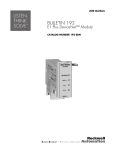
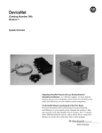
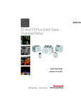
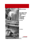
1
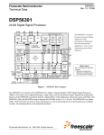
DSA I/O for
Distributed
Starters
Cat. Nos. 100-DNY41R,
100-DNY42R, 100-DNY42S
User Manual
Important User Information
!
" #$ %% ! " &
& '
ATTENTION
$
) !
'
• (
• (
• ( IMPORTANT
$
European Communities (EC) Directive Compliance
$ *+ + , ++ $
EMC Directive
* -
./01120+* +
*
!+3*" '
•
+4 566.% 7 +3* 8 # + 9
7 8 $
+
•
+4 566.7 7 +3* 8 # $
9
7 8 $
+
Low Voltage Directive
* -
:10710++* ; <
+4 2%%1% 7 9 *
9
7 +
&
= +4 2%%1% 7 $
> # # = 4 $
%::6 ?%
Preface
Manual Objectives
%66 -4
- %66 -4
IMPORTANT
& ( -4
Who Should Use This Manual
@ @ -4
-4
@ &4
> -4
!& *
4 /15: -4+;1" Vocabulary
$ '
A-B
9 *
9;* ;*
-4
-4+
4+*
#4-
Publication 100-UM005A-EN-P - April 2001
Preface
ii
Firmware Version
'
=&4 C = & 4
5 C = ) !" C - 66% C 3 4 Reference Manuals
= -;'
• -; , 3 9
4 *$# ,366% +4 9
• -; D
9
4 *$# D66% +4 9
= *
; %:52 -4 '
• *
; -4
3 $
$
9
4 %:52 522
• *
; -4
3 *
3
9
4 %:52 25%/
= ;* 566 %:?: -4 '
• -4
3 $
$
9
4 %:?: 257
• -4
3 *
3 9
4 %:?: 5.
= 9;*5 %::% -4 '
• -4
3 $
$
9
4 %::% 5%?
• -4
3 *
3 9
4 %::% 25%%.
-4
'
• -4
* 9 $
3
9
4 %?.5 2:%
IMPORTANT
& -4
* 9 $
3
!9
4 %?.5 2:%" -4
$ Publication 100-UM005A-EN-P - April 2001
iii
Preface
$ & E * '
'00
Manual Organization
Chapter
Title
Description
Preface
Manual objectives, audience, vocabulary, manual conventions,
safety precautions, DeviceNet compatibility
1
Product Overview
Packing list, product description, catalog numbers, European
Union Directive compliance
2
Installation
Installation cabling and hardware
3
DeviceNet Node
Commissioning
Basic Configuration, input/output assemblies, network control,
scan lists
4
Parameter Descriptions
Descriptions of all configuration and status parameters
5
Explicit Messaging
Using explicit messaging to read inputs and write outputs
6
Troubleshooting
LED indications and fault descriptions
7
Specifications
Environmental, electrical, and communication specifications
8
DeviceNet Information
DeviceNet message types and object classes
Safety Precautions
ATTENTION
!
E -4
- = ) 0 Publication 100-UM005A-EN-P - April 2001
Chapter
1
Product Overview
Chapter Objectives
$ '
• -
• *
• -4
• -; • + , -
Bill of Material
@ - '
Item
Description
Quantity
DSA Module
22.5 mm Series B module
1
Input Plug
Black Pluggable terminal block, 5 mm spacing
1
Output Plug
Black Pluggable terminal block, 5 mm spacing
1
DeviceNet Plug
Grey terminal block with test points (5.08 mm)
1
Device Description
%66 -4
-4
$0E $
! 7 1 8 8 " !
" ( !" %66 -4
& A-;B *
-
Publication 100-UM005A-EN-P - April 2001
1-2
Figure 1.1 DeviceNet Starter Auxiliary
DeviceNet
Connector
Input
Connector
Header
M odu le/N etw ork S tatu s
L ED
P
U
T
O
U
Output
Connector
T
Input
Status LED
I
N
P
U
T
Ouput
Status LED
O
U
T
P
U
T
Catalog Number Explanation
-4
= %7
Figure 1.2 Catalog Number Explanation
100 - DN
Y
4
1
R
First Position
Second Position
Third Position
Bulletin Number
Package Width
Number of Inputs/Outputs Input Voltage
Output Type
4 = 4-in/2-out
S = Solid-State
R = Relay
100-DN = DeviceNet
Y=22.5 mm
Publication 100-UM005A-EN-P - April 2001
Fourth Position
1 = 120V AC
2 = 24V DC
Fifth Position
1-3
DeviceNet Compatibility
- *
# 7 -4
9
$
$0E !*E"0 $0E 0 F # ? =
4 &F &
-
F *
*
<
DeviceLogix Compatibility
-; & - -; A-; +
B =
&4
-4
-; &4
-4
16666 +- -; &4
16666 7 +- '
'000
00
+
3) & 5 +- &
A&
+- B 1 1 +- &4
European Union Directive Compliance
> + , ++ * -
./01120++* +
*
!+3*" '
• +4 566.% % +3* # + 9
% &
+
• +4 566.% 7 +3* # + 9
7 $
+
• +4 566.7 % +3* # $
9
% &
+
• +4 566.7 7 +3* # $
9
7 $
+
• 26/?: %0%% 26/?: ; <
*
! " * -
:10710++* ; <
$+* /?:0+4 26/?: ; <
*
Publication 100-UM005A-EN-P - April 2001
1-4
Publication 100-UM005A-EN-P - April 2001
Chapter
2
Installation
Chapter Objectives
'
• - • 3
• *
& -4
- Storage and Operation
'
• G?6°HI.5°* ! ?6°H%.5°="
• 6H/5J • • 9
• E
6°HI26°* !17°H%?6°="
Mounting and Dimensions
- -$4 & ! = 7%" 1:? !% %07 "
-4
1:? !% %07 "
Publication 100-UM005A-EN-P - April 2001
2-2
Figure 2.1 Bulletin 100-DNY Dimensions
Dimensions shown in inches (mm), Not intended for manufacturing purposes.
Dimensions shown in inches (mm)
4.33
(110)
DIN Rail
.89 (22.5)
Top
.43
(10.9)
Input Wiring
Input Wiring
.71
(18.16)
.71 (18.16)
1.50
(38.11)
1.29
.20 (32.81)
(.5)
DIN Rail
3.07
(78)
.177
(4.5)
.22
(5.7)
3.35
(85)
3.63
(92.22)
Panel Mounting
Screw Location
I
N
P
U
T
DIN Rail
1.50
(38.05)
.71 (18.16)
O
U
T
P
U
T
.10
(2.5)
Output Wiring
Front
Output Wiring
DIN Rail Mounting Clip
Side
Back
DSA Wiring Diagrams
= 77 7? -
Publication 100-UM005A-EN-P - April 2001
2-3
Figure 2.2 Wiring Diagram - 24V DC Input/Relay Output
(Cat. No. 100-DNY42R shown)
DNET
(RED)
24V+
CAN H (WHITE)
External
Connections
CAN L (BLUE)
DNET
(BLACK)
24VIN 3 NEG
V+ IN 0 IN 1 IN 2
DC
DC
OUT B OUT A
4
2
3
1
Figure 2.3 Wiring Diagram - 24V DC Input/Solid-State Output
(Cat. No. 100-DNY42S Shown)
External
Connections
DNET
(RED)
24V+
CAN H (WHITE)
CAN L (BLUE)
DNET
(BLACK)
24VV+ IN 0
IN 3 NEG
IN 1 IN 2
DC
DC
OUT B
OUT A
4
3
2
1
+
24V
- P.S.
Publication 100-UM005A-EN-P - April 2001
2-4
Figure 2.4 Wiring Diagram - 120V AC Input/Relay Output
(Cat. No. 100-DNY 41R shown)
O
USE 75 C COPPER WIRE MIN.
TIGHTENING TORQUE:
4.4-5.3 LB.-IN. (0.5 - 0.6 Nm)
WIRE SIZE: 14 AWG (2.5mm2)
DNET
(RED)
24V+
L1
CAN H (WHITE)
CAN L (BLUE)
120V AC
DNET
(BLACK)
24V-
L2
VCOM IN 0 IN 1
External
Connections
IN 2 IN 3
DNY41R
OUT B OUT A
4
3
2
1
Input and Output Connections
= 75 Figure 2.5 Input/Output Connections
DeviceNet
Connector
Black Plug
5mm Pitch
T
P
U
T
Input
Status LED
O
U
Input
Connector
Header
I
N
P
U
T
Grey Plug
Black
5mm Pitch
Ouput
Status LED
O
U
T
P
U
T
Publication 100-UM005A-EN-P - April 2001
Output
Connector
Header
2-5
24V DC Input DSA
= 7?< -* - <I -4
!7?<I"
ATTENTION
- 7?< -* !
120V AC Input DSA
%76< * - %76< 24V DC Solid-State Output DSA
7?< -* +
7?<I !9 %"
+
7?< !9 ?" Relay Output DSA
& E
- 7?60%76< * 7?< -* *
: !
"
IMPORTANT
& *
: Publication 100-UM005A-EN-P - April 2001
2-6
Typical Wiring Examples
Figure 2.6 Motor Starter with DSA (24V DC Input/Relay Output) and Sensor
Connection
NEG "DSA"
IN 3 "DSA"
V+ "DSA"
M
DC
DC
NEMA Wiring Diagram
①
Remote Device: 42 GRM 9000-QD or equivalent. Consult factory for equivalent.
②
Transient Suppressor recommended
③
It is suggested that coil power be supplied from a separate power source
➃ Remote Device: Consult factory for proper 3-wire photoswitch application
Publication 100-UM005A-EN-P - April 2001
193-DNY42R
2-7
Figure 2.7 Motor Starter with DSA (24V DC Input/Relay Output) and Sensor
Connection
IEC Wiring Diagram
➃
V+
DSA Cat. No. 100-DNY42R
① Remote Device: 42 GRM 9000-QD or equivalent. Consult factory for equivalent.
② Transient Suppressor recommended
③ It is suggested that coil power be supplied from a separate power source
➃ Remote Device: Consult factory for proper 3-wire photoswitch application.
Figure 2.8 Motor Starter with DSA (24V DC Input/Solid-State Output) and Sensor
Connection
②
NEMA Wiring Diagram
① Remote Device: 871 TM DHSNE or equivalent:
② Transient Suppressor recommended
③ Suggested external 24V DC power supply
Publication 100-UM005A-EN-P - April 2001
2-8
Figure 2.9 Motor Starter with DSA (24V DC Input/Solid-State Output) and
Proximity Sensor Connection
IEC Wiring Diagram
V+
DSA Cat. No. 100-DNY42S
① Remote Device: 871 TM DHSNE or equivalent:
② Transient Suppressor recommended
③ Suggested external 24V DC power supply
Publication 100-UM005A-EN-P - April 2001
2-9
Figure 2.10 Reversing Motor Starter with DSA (120V AC Input / Relay Output)
Incoming Lines
L1
NEMA Wiring Diagram
L2
L3
11
1L1
1L2
Fuse
Clips
(W hen
used)
1L3
DS
1
7
1L1
3
A1
1L2
1
L1
3
L2
T1
2
T2
4
R
6
9
1L3
5
L3
13
T3
6
14
7
3
1
A2
A1
1L1
1L2
1
L1
3
L2
T1
2
T2
4
8
1L3
5
L3
13
T3
6
14
F
1L1
3
A2
1L3
H1
1
2
3
1L2
H2
"J"
H3
H4
1L1
1L2
5
1
GND
A2
X2
X1
TRANS.
9
5
T1
2
5
X
2
9
6
9
7
T2
4
T1
1
0
1
9
8
BLACK
BLUE
BARE
WHITE
RED
DeviceNet
Comm Cable
T3
6
T2
T3
X2
8
9
10
11
X2
1
M
2
6
DNET 24VCANL
SHIELD
CANH
DNET 24V+
VCOM
com
IN 0
IN 1
IN 2
IN 3
OUT A (1)
OUT A (2)
OUT B (3)
OUT B (4)
Cat. No. 100-DNX41R
Figure 2.11 Reversing Motor Starter with DSA (120V AC Input / Relay Output)
IEC Wiring Diagram
DSA Cat. No. 100-DNY41R
Publication 100-UM005A-EN-P - April 2001
2-10
DeviceNet Connector
- -4
*
-4
*
: Terminal
Signal
Function
Color
1
COM
Common
Black
2
CAN_L
Signal Low
Blue
3
SHIELD
Shield
Uninsulated
4
CAN_H
Signal High
White
5
VDC+
Power Supply
Red
Wiring the DeviceNet Connector
Single-position DeviceNet terminal block
Gray Connector, 5.08 mm pitch
Black 1
Blue 2
Bare 3
Caution
DO NOT APPLY EXTERNAL POWER
TO INPUT TERMINALS
MAY CAUSE EQUIPMENT DAMAGE
1
Allen-Bradley
0
White 4
NOTE: Fasten the two screws on the DeviceNet plug to the top
of the DSA module to avoid accidental disconnection.
Publication 100-UM005A-EN-P - April 2001
Red 5
Chapter
3
DeviceNet Node Commissioning
Chapter Objectives
- -4
'
• - -4
4
• %:?: -4 -4
-
IMPORTANT
%:?: -4 &4
> -4
%::% -4 %:52 -4 Getting Started
> A
B - = 1% 4
A
B - 3* $- 21
3* $- ? ! "
Figure 3.1 DeviceNet Network Diagram
&4
> AEB # AEB &4
> -4
= '
# = A4
B AEB
$# * -4
9* $ %::6 K= Publication 100-UM005A-EN-P - April 2001
3-2
%# * &'
(# * &'
&4
> AB -4
> AB '
Publication 100-UM005A-EN-P - April 2001
3-3
, AB &4
> = 16%6? &4
> - +
-
!+-" - A,
-B &4
> $ - A,
-B &4
> A* 4 B E
+- Registering an EDS File
&4
> 4
- 3* $- 21 A,( -B
+- +- - '
'000
00
+
3) & 5 +- # +- A+- >(HB AB '
Publication 100-UM005A-EN-P - April 2001
3-4
$# * ) '
Publication 100-UM005A-EN-P - April 2001
3-5
%# * A&
+- !"B '
Publication 100-UM005A-EN-P - April 2001
3-6
(# * AB +- > +- L AB '
*# * AMB '
Publication 100-UM005A-EN-P - April 2001
3-7
+# * M '
1H[W
Publication 100-UM005A-EN-P - April 2001
3-8
,# * -. &4
> -4
4
- &4
> Changing the Node Address
+ -4
A3* $-B
6 21 - 3* $- N 3* $- 2?H// !
- 3* $- //" 3* $- 6H21 Publication 100-UM005A-EN-P - April 2001
3-9
# 3* $- &4
> A4 *HB AB '
$# * H '
Publication 100-UM005A-EN-P - April 2001
3-10
%# * - &' 4 * '
(# +
4 A4 B $ ? * // > 4 A*
B > .
Device Parameter Programming - Consumed and Produced I/O
Assemblies
* $0E ( - * $0E * $0E AE
B
9;* -
9 $0E ( - 9 $0E 9 $0E A$
B 9;* - Publication 100-UM005A-EN-P - April 2001
3-11
- * 9 9
%1 * $0E 9
%? 9 $0
E 9
%1 %? A*
<B A- 9
B &4
> +
Consumed I/O Assemblies
9
%1 * $0E A17B * $0E
$
17 '
Table 3.A
Byte
Bit 7
Bit 6
Bit 5
Bit 4
Bit 3
Bit 2
0
Bit 1
Bit 0
Output B
Output A
9
%1 * $0E A%.1B * $0E
$
%.1 '
Table 3.B
Byte
Bit 7
Bit 6
Bit 5
Bit 4
Bit 3
Bit 2
Bit 1
Bit 0
0
Net In 7
Net In 1
Net In 5
Net In 4
Net In 3
Net In 2
Output
B/Net
In 1
Output
A/Net
In 0
1
Net In
15
Net In
14
Net In
13
Net In
12
Net In
11
Net In
10
Net In 9
Net In 8
Produced I/O Assemblies
9
%? 9 $0E A1B 01&
.. 0. % '
Table 3.C
Byte
Bit 7
Bit 6
Bit 5
Bit 4
0
Bit 3
Bit 2
Bit 1
Bit 0
Input 3
Input 2
Input 1
Input 0
9
%? 9 $0E A%65B 01&
.. 0. * '
Table 3.D
Byte
Bit 7
0
Input
Fault
Bit 6
Bit 5
Bit 4
Bit 3
Bit 2
Bit 1
Bit 0
Output B
Fault
Output A
Fault
Input 3
Input 2
Input 1
Input 0
Publication 100-UM005A-EN-P - April 2001
3-12
4
9 $0E %65 ? 07
-
9
%? 9 $0E A%.6B 01&
.. 0. 2
'
Table 3.E
Byte
Bit 7
Bit 6
Bit 5
Bit 4
0
Bit 3
Bit 2
Bit 1
Bit 0
Input 3
Input 2
Input 1
Input 0
1
4
9 $0E %.6 7 9;*
9
%? 9 $0E A%.%B 01&
.. 0. 2 '
Table 3.F
Byte
Bit 7
Bit 6
Bit 5
Bit 4
Bit 3
Bit 2
0
Bit 1
Bit 0
Output
B State
Output
A State
1
4
9 $0E %.% 7 9;*
9
%? 9 $0E A%.7B 01&
.. 0. 2$ '
Table 3.G
Byte
Bit 7
Bit 6
Bit 5
0
Bit 4
Bit 3
Bit 2
Bit 1
Bit 0
Output
B Fault
Output
A Fault
Input
Fault
1
4
9 $0E %.7 7 9;* 9
%?
9 $0E A%.?B 01& .. 0.
2( '
Publication 100-UM005A-EN-P - April 2001
3-13
Table 3.H
Byte
Bit 7
Bit 6
Bit 5
Bit 4
Bit 3
Bit 2
Bit 1
Bit 0
0
Net Out
7
Net Out
6
Net Out
5
Net Out
4
Net Out
3
Net Out
2
Net Out
1
Net Out
0
1
Net Out
15
Net Out
14
Net Out
13
Net Out
12
Net Out
11
Net Out
10
Net Out
9
Net Out
8
9
%? 9 $0E A%.5B 01&
.. 0. 2* '
Table 3.I
Byte
Bit 7
Bit 6
Bit 5
Bit 4
Bit 3
Bit 2
Bit 1
Bit 0
0
COS
Cnxn
Idle
Poll
Cnxn
Idle
COS
Cnxn
Faulted
Poll
Cnxn
Faulted
Explicit
Cnxn
Fault
COS
Cnxn
Poll
Cnxn
Explicit
Cnxn
Module
Fault
Network
Fault
1
9
%? 9 $0E A%.2B 01&
.. 0. 2+ '
Table 3.J
Byte
Bit 7
Bit 6
Bit 5
Bit 4
Bit 3
Bit 2
Bit 1
Bit 0
0
Function
Block 7
Function
Block 6
Function
Block 5
Function
Block 4
Function
Block 3
Function
Block 2
Function
Block 1
Function
Block 0
1
Function
Block 15
Function
Block 14
Function
Block 13
Function
Block 12
Function
Block 11
Function
Block 10
Function
Block 9
Function
Block 8
9
%? A%.:B .. 01&
.. 0. 2, '
Table 3.K
Byte
Bit 7
Bit 6
Bit 5
Bit 4
Bit 3
Bit 2
Bit 1
Bit 0
0
Function
Block 7
Function
Block 6
Function
Block 5
Function
Block 4
Function
Block 3
Function
Block 2
Function
Block 1
Function
Block 0
1
Function
Block 15
Function
Block 14
Function
Block 13
Function
Block 12
Function
Block 11
Function
Block 10
Function
Block 9
Function
Block 8
9
%? A%..B .. 01&
.. 0. 22 '
Publication 100-UM005A-EN-P - April 2001
3-14
Table 3.L
Byte
Bit 7
Bit 6
Bit 5
Bit 4
Bit 3
Bit 2
Bit 1
Bit 0
0
Function
Block 7
Function
Block 6
Function
Block 5
Function
Block 4
Function
Block 3
Function
Block 2
Function
Block 1
Function
Block 0
1
Function
Block 15
Function
Block 14
Function
Block 13
Function
Block 12
Function
Block 11
Function
Block 10
Function
Block 9
Function
Block 8
9
%? A%66B .. 01&
.. 0. '
Table 3.M
Byte
Bit 7
Bit 6
0
0
Value pointed to by parameter #15 (low byte)
1
2
1
7
Bit 3
Value pointed to by parameter #16 (low byte)
Value pointed to by parameter #16 (high byte)
2
5
6
Bit 4
Value pointed to by parameter #15 (high byte)
3
4
Bit 5
Value pointed to by parameter #17 (low byte)
Value pointed to by parameter #17 (high byte)
0
Value pointed to by parameter #18 (low byte)
Value pointed to by parameter #18 (high byte)
Publication 100-UM005A-EN-P - April 2001
Bit 2
Bit 1
Bit 0
3-15
9 * $0E &4
> AEB # - - ? &4
>
'
$# * A- 9
B '
Publication 100-UM005A-EN-P - April 2001
3-16
%# * A3/B -
'
(# , A#B A-4
B '
9
%1 %? A*
<B +
Publication 100-UM005A-EN-P - April 2001
3-17
IMPORTANT
IMPORTANT
$
L ( ! " 9
%1 %?
> 9
%1 %? ( - - * AB 4! B Mapping to the Scanner’sScanlist
- %:?: -4 &4
> AEB # - A%:?: -4 3B A&4
> -4
B '
Publication 100-UM005A-EN-P - April 2001
3-18
$# * A
B '
%# * 3/ '
(# > '
Publication 100-UM005A-EN-P - April 2001
3-19
*# ! A6? - ?07 !%66 -4@?7"
566%B " A -B AMB = '
+# +
$0E - A
B A+
$0E 9
HB - A
B
'
Publication 100-UM005A-EN-P - April 2001
3-20
,# '
Table 3.N
Field
Entry
Polled
Enabled (checked)
Rx Size
Equal to DSA Input Assembly size (Produced I/O Assembly size)
Tx Size
Equal to DSA Output Assembly size (Consumed I/O Assembly size)
Poll Rate
Every Scan
- * !*E" * $0E '
Table 3.O
Field
Entry
Change of State/Cyclic
Enabled (checked)
Rx Size
Equal to DSA Input Assembly size (Produced I/O Assembly size)
Tx Size
Equal to DSA Output Assembly size (Consumed I/O Assembly size)
Heartbeat Rate
As appropriate
&'
Input/Output Mapping In the Scanlist
E $0E / / - Publication 100-UM005A-EN-P - April 2001
3-21
# * A$
B %:?: -4 3 '
$'%% $
-
Publication 100-UM005A-EN-P - April 2001
3-22
$# * AE
B %:?: -4 3 '
E'%% E
-
%# * // '
(# * @ Publication 100-UM005A-EN-P - April 2001
Chapter
4
Parameter Descriptions
Chapter Objectives
Parameter Programming
& *
1 G 4 * &4
> -4
- 9
9 G
* 9 $0E %1 %?
IMPORTANT
9
&4
> -4
- Publication 100-UM005A-EN-P - April 2001
4-2
Parameter Groups
- 3
9 -4
$0E Monitor Params
DNet Setup
I/O Setup
1. Hdw In States
10. Autobaud Enable
11. Off-to-On Delay
2. Hdw Out States
13. Consumed Assembly
12. On-to-Off Delay
3. IO Fault States
14. Produced I/O Assembly
28. OutA Fault State
4. Network Inputs
15. Produced I/O Assy Word 0
29. OutA Fault Value
5. Network Outputs
16. Produced I/O Assy Word 1
30. OutA Idle State
6. Module Status
17. Produced I/O Assy Word 2
31. OutA Idle Value
7. Fn Blocks 1-16
18. Produced I/O Assy Word 3
32. OutB Fault State
8. Fn Blocks 17-32
19. Input COS Mask
33. OutB Fault Value
9. Fn Blocks 33-42
20. Module COS Mask
34. OutB Idle State
21. FB1-16 COS Mask
35. OutB Idle Value
22. FB17-32 COS Mask
23. FB33-42 COS Mask
24. Set to Defaults
25. MAC ID Switches
26. Network Override
27. Comm Override
Publication 100-UM005A-EN-P - April 2001
4-3
Monitor Params Group
Hdw In States
This parameter provides status
information on the states of the 4
hardware inputs of the DSA.
1 = ON
0 = OFF
Parameter Number
1
Access Rule
Read Only
Data Type
WORD
Object Mapping
0x0004-0xB4-0x03
Group
Monitor Params
Units
—
Minimum Value
0000000000000000
Maximum Value
0000000000001111
Default Value
0000000000000000
Bit
15
Function
14
13
12
11
10
9
8
7
6
5
4
3
2
1
0
X
Input 0
X
Input 1
X
Input 2
X
Hdw Out States
This parameter provides status
information on the states of the 2
hardware outputs of the DSA.
1 = ON
0 = OFF
Input 3
Parameter Number
2
Access Rule
Read Only
Data Type
WORD
Object Mapping
0x0004-0xB5-0x03
Group
Monitor Params
Units
—
Minimum Value
0000000000000000
Maximum Value
0000000000000011
Default Value
0000000000000000
Bit
15
Function
14
13
12
11
10
9
8
7
6
5
4
3
2
1
0
X
X
Output A
Output B
Publication 100-UM005A-EN-P - April 2001
4-4
IO Fault Status
This parameter provides status
information on the fault status of the
DSA inputs and outputs. Note that
input faults can only be detected on
units with 24V DC inputs, and output
faults can only be detected on units
with Solid State outputs
1 = FAULTED
0 = NOT FAULTED
Parameter Number
3
Access Rule
Read Only
Data Type
WORD
Object Mapping
0x0004-0xB6-0x03
Group
Monitor Params
Units
—
Minimum Value
0000000000000000
Maximum Value
0000000000000111
Default Value
0000000000000000
Bit
15
Function
14
13
12
11
10
9
8
7
6
5
4
3
2
1
0
X
X
X
Publication 100-UM005A-EN-P - April 2001
Input Fault
Output A
Fault
Output B
Fault
4-5
Network Inputs
This parameter provides status
information on the states of the
network inputs. Network inputs
are consumed by a DSA and may
be used as inputs to function
blocks in a DeviceLogix program.
1 = ON
0 = OFF
Parameter Number
4
Access Rule
Read Only
Data Type
WORD
Object Mapping
0x0004-0xB7-0x03
Group
Monitor Params
Units
—
Minimum Value
0000000000000000
Maximum Value
1111111111111111
Default Value
0000000000000000
Bit
15
Function
14
13
12
11
10
9
8
7
6
5
4
3
2
1
0
X
X
X
X
X
X
X
X
X
X
X
X
X
X
X
X
Network Input 0
Network Input 1
Network Input 2
Network Input 3
Network Input 4
Network Input 5
Network Input 6
Network Input 7
Network Input 8
Network Input 9
Network Input 10
Network Input 11
Network Input 12
Network Input 13
Network Input 14
Network Input 15
Publication 100-UM005A-EN-P - April 2001
4-6
Network Outputs
This parameter provides status
information on the states of the
network outputs. DeviceLogix
programs can drive the state of
network outputs which are in turn
produced on the network by the
DSA.
1 = ON
0 = OFF
Parameter Number
5
Access Rule
Read Only
Data Type
WORD
Object Mapping
0x0004-0xB8-0x03
Group
Monitor Params
Units
—
Minimum Value
0000000000000000
Maximum Value
0000000011111111
Default Value
0000000000000000
Bit
15
Function
14
13
12
11
10
9
8
7
6
5
4
3
2
1
X
X
X
X
X
X
Publication 100-UM005A-EN-P - April 2001
0
Network
Output 0
X
Network
Output 0
Network
Output 0
Network
Output 0
Network
Output 0
Network
Output 0
Network
Output 0
Network
Output 0
4-7
Module Status
This parameter provides status
information on the state of the DSA
as outlined in the table below.
1 = ON or Present
0 = OFF or Not Present
Parameter Number
6
Access Rule
Read Only
Data Type
WORD
Object Mapping
0x0004-0xB9-0x03
Group
Monitor Params
Units
—
Minimum Value
0000000000000000
Maximum Value
0000001111111111
Default Value
0000000000000000
Bit
15
Function
14
13
12
11
10
9
8
7
6
5
4
3
2
1
0
X
X
X
X
X
X
X
X
X
X
Exp Cnxn
Exists
Poll Cnxn
Exists
COS Cnxn
Exists
Exp Cnxn
Fault
Poll Cnxn
Fault
COS Cnxn
Fault
Poll Cnxn
Idle
COS Cnxn
Idle
Network
Fault
Module
Fault
Publication 100-UM005A-EN-P - April 2001
4-8
Fn Blocks 1…16
This parameter provides status
information on the state of
Function Blocks 1…16.
1 = ON
0 = OFF
Parameter Number
7
Access Rule
Read Only
Data Type
WORD
Object Mapping
0x0004-0xBA-0x03
Group
Monitor Params
Units
—
Minimum Value
0000000000000000
Maximum Value
1111111111111111
Default Value
0000000000000000
Bit
15
Function
14
13
12
11
10
9
8
7
6
5
4
3
2
1
0
X
X
X
X
X
X
X
X
X
X
X
X
X
X
X
X
Publication 100-UM005A-EN-P - April 2001
FB 1
Output
FB 2
Output
FB 3
Output
FB 4
Output
FB 5
Output
FB 6
Output
FB 7
Output
FB 8
Output
FB 9
Output
FB 10
Output
FB 11
Output
FB 12
Output
FB 13
Output
FB 14
Output
FB 15
Output
FB 16
Output
4-9
Fn Blocks 17…32
This parameter provides status
information on the state of
Function Blocks 17…32.
1 = ON
0 = OFF
Parameter Number
8
Access Rule
Read Only
Data Type
WORD
Object Mapping
0x0004-0xBB-0x03
Group
Monitor Params
Units
—
Minimum Value
0000000000000000
Maximum Value
1111111111111111
Default Value
0000000000000000
Bit
15
Function
14
13
12
11
10
9
8
7
6
5
4
3
2
1
0
X
X
X
X
X
X
X
X
X
X
X
X
X
X
X
X
FB 17
Output
FB 18
Output
FB 19
Output
FB 20
Output
FB 21
Output
FB 22
Output
FB 23
Output
FB 24
Output
FB 25
Output
FB 26
Output
FB 27
Output
FB 28
Output
FB 29
Output
FB 30
Output
FB 31
Output
FB 32
Output
Publication 100-UM005A-EN-P - April 2001
4-10
Fn Blocks 33…42
This parameter provides status
information on the state of
Function Blocks 33…42.
1 = ON
0 = OFF
Parameter Number
9
Access Rule
Read Only
Data Type
WORD
Object Mapping
0x0004-0xBC-0x03
Group
Monitor Params
Units
—
Minimum Value
0000000000000000
Maximum Value
0000001111111111
Default Value
0000000000000000
Bit
15
Function
14
13
12
11
10
9
8
7
6
5
4
3
2
1
0
X
X
X
X
X
X
X
X
X
X
Publication 100-UM005A-EN-P - April 2001
FB 33
Output
FB 34
Output
FB 35
Output
FB 36
Output
FB 37
Output
FB 38
Output
FB 39
Output
FB 40
Output
FB 41
Output
FB 42
Output
4-11
DNet Setup Group
Autobaud Enable
Parameter Number
10
Access Rule
Read/Write
Data Type
BOOL
Object Mapping
0x00B4-0x01-0x0F
Group
DNet Setup
Units
—
Minimum Value
0 = Disable
Maximum Value
1 = Enable
Default Value
1 = Enable
Parameter Number
13
Access Rule
Read/Write
Data Type
USINT
Object Mapping
0x00B4-0x01-0x10
Group
DNet Setup
Units
—
Minimum Value
0
Maximum Value
183
Default Value
32
Produced I/O Assembly
Parameter Number
14
This parameter is used to select
the desired produced I/O assembly.
The user may choose from the
following valid assemblies
3 – ODVA Input Assembly
(1 byte)
100 – Parameter-Based
Assembly (0, 2, 4, 6 or
8 bytes)
105 – Default DSA Input
Assembly (1 byte)
180 – Hardware Input
Assembly (2 bytes)
181 – Hardware Output
Status Assembly (2 bytes)
182 – I/O Fault Status
Assembly (2 bytes)
184 – Network Outputs
Assembly (2 bytes)
185 – Module Status
Assembly (2 bytes)
186 – Function Block 1…16
Assembly (2 bytes)
187 – Function Block 17…32
Assembly (2 bytes)
188 – Function Block 33…42
Assembly (2 bytes)
Access Rule
Read/Write
Data Type
USINT
Object Mapping
0x00B4-0x01-0x11
Group
DNet Setup
Units
—
Minimum Value
0
Maximum Value
188
Default Value
105
When this parameter is enabled,
the device will attempt to
determine the network baud rate
and set its baud rate to the same,
provided network traffic exists.
At least one node with an
established baud rate must exist
on the network for autobaud to
occur.
Consumed I/O Assembly
This parameter is used to select
the desired consumed I/O
assembly.
The user may choose from the
following valid assemblies:
32 – Default DSA Output
Assembly (1 byte)
183 – Network Input
Assembly (2 bytes)
Publication 100-UM005A-EN-P - April 2001
4-12
Produced I/O Assy Word 0
This parameter assigns the
parameter value to be placed in
Word 0 of Produced I/O Assembly
100.
Produced I/O Assy Word 1
This parameter assigns the
parameter value to be placed in
Word 1 of Produced I/O Assembly
100.
Produced I/O Assy Word 2
This parameter assigns the
parameter value to be placed in
Word 2 of Produced I/O Assembly
100.
Produced I/O Assy Word 3
This parameter assigns the
parameter value to be placed in
Word 3 of Produced I/O Assembly
100.
Parameter Number
15
Access Rule
Read/Write
Data Type
USINT
Object Mapping
0x00B4-0x01-0x07
Group
DNet Setup
Units
—
Minimum Value
0
Maximum Value
9
Default Value
1
Parameter Number
16
Access Rule
Read/Write
Data Type
USINT
Object Mapping
0x00B4-0x01-0x08
Group
DNet Setup
Units
—
Minimum Value
0
Maximum Value
9
Default Value
3
Parameter Number
17
Access Rule
Read/Write
Data Type
USINT
Object Mapping
0x00B4-0x01-0x09
Group
DNet Setup
Units
—
Minimum Value
0
Maximum Value
9
Default Value
5
Parameter Number
18
Access Rule
Read/Write
Data Type
USINT
Object Mapping
0x00B4-0x01-0x0A
Group
DNet Setup
Units
—
Minimum Value
0
Maximum Value
9
Default Value
6
Publication 100-UM005A-EN-P - April 2001
4-13
Input COS Mask
This parameter allows the installer
to define the change of state
conditions that will result in a
change of state message being
produced.
1 = Enabled
0 = Disabled
Parameter Number
19
Access Rule
Read/Write
Data Type
WORD
Object Mapping
0x00B4-0x01-0x0D
Group
DNet Setup
Units
—
Minimum Value
0000000000000000
Maximum Value
0000000000001111
Default Value
0000000000001111
Bit
15
Function
14
13
12
11
10
9
8
7
6
5
4
3
2
1
0
X
X
X
X
Input 0
Input 1
Input 2
Input 3
Publication 100-UM005A-EN-P - April 2001
4-14
Module COS Mask
This parameter allows the installer
to define the change of state
conditions that will result in a
change of state message being
produced.
1 = Enabled
0 = Disabled
Parameter Number
20
Access Rule
Read/Write
Data Type
WORD
Object Mapping
0x00B4-0x01-0x28
Group
DNet Setup
Units
—
Minimum Value
0000000000000000
Maximum Value
0000001111111111
Default Value
0000000000000000
Bit
15
Function
14
13
12
11
10
9
8
7
6
5
4
3
2
1
0
X
X
X
X
X
X
X
X
X
X
Publication 100-UM005A-EN-P - April 2001
Exp Cnxn
Exists
Poll Cnxn
Exists
COS Cnxn
Exists
Exp Cnxn
Fault
Poll Cnxn
Fault
COS Cnxn
Fault
Poll Cnxn
Idle
COS Cnxn
Idle
Network
Fault
Module
Fault
4-15
FB1-16 COS Mask
This parameter allows the installer
to define the change of state
conditions that will result in a
change of state message being
produced.
1 = Enabled
0 = Disabled
Parameter Number
21
Access Rule
Read/Write
Data Type
WORD
Object Mapping
0x00B4-0x01-0x29
Group
DNet Setup
Units
—
Minimum Value
0000000000000000
Maximum Value
1111111111111111
Default Value
0000000000000000
Bit
15
Function
14
13
12
11
10
9
8
7
6
5
4
3
2
1
0
X
X
X
X
X
X
X
X
X
X
X
X
X
X
X
X
FB 1
Output
FB 2
Output
FB 3
Output
FB 4
Output
FB 5
Output
FB 6
Output
FB 7
Output
FB 8
Output
FB 9
Output
FB 10
Output
FB 11
Output
FB 12
Output
FB 13
Output
FB 14
Output
FB 15
Output
FB 16
Output
Publication 100-UM005A-EN-P - April 2001
4-16
FB17-23 COS Mask
This parameter allows the installer
to define the change of state
conditions that will result in a
change of state message being
produced.
1 = Enabled
0 = Disabled
Parameter Number
22
Access Rule
Read/Write
Data Type
WORD
Object Mapping
0x00B4-0x01-0x2A
Group
DNet Setup
Units
—
Minimum Value
0000000000000000
Maximum Value
1111111111111111
Default Value
0000000000000000
Bit
15
Function
14
13
12
11
10
9
8
7
6
5
4
3
2
1
0
X
X
X
X
X
X
X
X
X
X
X
X
X
X
X
X
Publication 100-UM005A-EN-P - April 2001
FB 17
Output
FB 18
Output
FB 19
Output
FB 20
Output
FB 21
Output
FB 22
Output
FB 23
Output
FB 24
Output
FB 25
Output
FB 26
Output
FB 27
Output
FB 28
Output
FB 29
Output
FB 30
Output
FB 31
Output
FB 32
Output
4-17
FB33-42 COS Mask
This parameter allows the installer
to define the change of state
conditions that will result in a
change of state message being
produced.
1 = Enabled
0 = Disabled
Parameter Number
23
Access Rule
Read/Write
Data Type
WORD
Object Mapping
0x00B4-0x01-0x2B
Group
DNet Setup
Units
—
Minimum Value
0000000000000000
Maximum Value
0000001111111111
Default Value
0000000000000000
Bit
15
Function
14
13
12
11
10
9
8
7
6
5
4
3
2
1
0
X
X
X
FB 34
Output
FB 35
Output
X
FB 36
Output
X
FB 37
Output
X
FB 38
Output
X
FB 39
Output
X
FB 40
Output
X
FB 41
Output
X
IMPORTANT
FB 33
Output
FB 42
Output
A
-
B -;
-
Set to Defaults
This parameter allows the installer
to reset all parameter settings to
the factory default values. After
parameter values have been reset
to the factory default settings, the
parameter automatically returns to
the “No Action” state.
1 = Set to Defaults
0 = No Action
Parameter Number
24
Access Rule
Read/Write
Data Type
BOOL
Object Mapping
0x00B4-0x01-0x13
Group
DNet Setup
Units
—
Minimum Value
0
Maximum Value
1
Default Value
0
Publication 100-UM005A-EN-P - April 2001
4-18
MAC ID Switches
Parameter Number
25
Access Rule
Read Only
Data Type
USINT
Object Mapping
0x0003-0x01-0x08
This parameter reflects the decimal Group
value of the rotary MAC ID
Units
switches on the side of the DSA.
Minimum Value
DNet Setup
—
0
Maximum Value
99
Default Value
99
Parameter Number
26
Access Rule
Read/Write
Data Type
BOOL
Object Mapping
0x001E-0x01-0x68
Group
DNet Setup
Units
—
Minimum Value
0
Maximum Value
1
Default Value
0
Comm Override
Parameter Number
27
Enabling this parameter allows
local logic to override normal
output behavior in the event of a
communication status change.
These events include all states
where the module is without an I/O
connection. This can happen if an
I/O connection does not exist, has
timed out, has been deleted or is
currently idle. The default is
“Disabled.”
Access Rule
Read/Write
Data Type
BOOL
Object Mapping
0x001E-0x01-0x69
Group
DNet Setup
Units
—
Minimum Value
0
Maximum Value
1
Default Value
0
Network Override
Enabling this parameter allows
local logic to override normal
output behavior in the event of a
network fault. Network faults
include duplicate Mac ID failure
and bus off conditions. The default
is “Disabled.”
Publication 100-UM005A-EN-P - April 2001
4-19
I/O Setup Group
Off-to-On Delay
Parameter Number
11
This parameter defines the time
necessary for the DSA to recognize
an off to on transition of a
hardware input signal. The value is
set in units of microseconds. Valid
values are:
0: No delay
1000: 1 ms delay
2000: 2 ms delay
4000: 4 ms delay
8000: 8 ms delay
16000: 16 ms delay
Access Rule
Read/Write
Data Type
UINT
Object Mapping
0x001D-0x01-0x06
Group
IO Setup
Units
microseconds (µs)
Minimum Value
0
Maximum Value
16000
Default Value
2000
On-to-Off Delay
Parameter Number
12
This parameter defines the time
necessary for the DSA to recognize
an on to off transition of a
hardware input signal. The value is
set in units of microseconds. Valid
values are:
0:No delay
1000: 1 ms delay
2000: 2 ms delay
4000: 4 ms delay
8000: 8 ms delay
16000: 16 ms delay
Access Rule
Read/Write
Data Type
UINT
Object Mapping
0x001D-0x01-0x07
Group
IO Setup
Units
microseconds (µs)
Minimum Value
0
Maximum Value
16000
Default Value
2000
OutA Fault State
Parameter Number
28
Access Rule
Read/Write
Data Type
BOOL
Object Mapping
0x0009-0x01-0x05
Group
IO Setup
Units
—
Minimum Value
0
Maximum Value
1
Default Value
0
Parameter Number
29
Access Rule
Read/Write
Data Type
BOOL
Object Mapping
0x0009-0x01-0x06
This parameter in conjunction with
parameter 29 defines how Output
A will respond when a DeviceNet
fault occurs. When set to 1, Output
A will hold the state prior to the
fault occurrence. When set to 0,
Output A will open or close as
determined by the setting of
parameter 29.
OutA Fault Value
This parameter determines the
state that Output A assumes when Group
a DeviceNet network fault occurs Units
and parameter 28 is set to “0”.
Minimum Value
IO Setup
—
0
Maximum Value
1
Default Value
0
Publication 100-UM005A-EN-P - April 2001
4-20
OutA Idle State
This parameter in conjunction with
parameter 31 defines how Output
A will respond when the DeviceNet
network is idle. When set to 1,
Output A will hold the state prior to
the idle condition. When set to 0,
Output A will open or close as
determined by the setting of
parameter 31.
OutA Idle Value
Parameter Number
30
Access Rule
Read/Write
Data Type
BOOL
Object Mapping
0x0009-0x01-0x07
Group
IO Setup
Units
—
Minimum Value
0
Maximum Value
1
Default Value
0
Parameter Number
31
Access Rule
Read/Write
Data Type
BOOL
Object Mapping
0x0009-0x01-0x08
This parameter determines the
state that Output A assumes when Group
the network is in idle mode and
Units
parameter 30 is set to “0”.
Minimum Value
OutB Fault State
This parameter in conjunction with
parameter 33 defines how Output
B will respond when a DeviceNet
fault occurs. When set to 1, Output
B will hold the state prior to the
fault occurrence. When set to 0,
Output B will open or close as
determined by the setting of
parameter 33
OutB Fault Value
IO Setup
—
0
Maximum Value
1
Default Value
0
Parameter Number
32
Access Rule
Read/Write
Data Type
BOOL
Object Mapping
0x0009-0x02-0x05
Group
IO Setup
Units
—
Minimum Value
0
Maximum Value
1
Default Value
0
Parameter Number
33
Access Rule
Read/Write
Data Type
BOOL
Object Mapping
0x0009-0x02-0x06
This parameter determines the
state that Output B assumes when Group
a DeviceNet network fault occurs Units
and parameter 32 is set to “0”
Minimum Value
IO Setup
—
0
Maximum Value
1
Default Value
0
Publication 100-UM005A-EN-P - April 2001
4-21
OutB Idle State
This parameter in conjunction with
parameter 35 defines how Output
B will respond when the DeviceNet
network is idle. When set to 1,
Output B will hold the state prior to
the idle condition. When set to 0,
Output B will open or close as
determined by the setting of
parameter 35.
OutB Idle Value
Parameter Number
34
Access Rule
Read/Write
Data Type
BOOL
Object Mapping
0x0009-0x02-0x07
Group
IO Setup
Units
—
Minimum Value
0
Maximum Value
1
Default Value
0
Parameter Number
35
Access Rule
Read/Write
Data Type
BOOL
Object Mapping
0x0009-0x02-0x08
This parameter determines the
state that Output B assumes when Group
the network is in idle mode and
Units
parameter 34 is set to “0”.
Minimum Value
IO Setup
—
0
Maximum Value
1
Default Value
0
Publication 100-UM005A-EN-P - April 2001
4-22
Publication 100-UM005A-EN-P - April 2001
Chapter
5
Explicit Messaging
Introduction
-4
+
-4
*
A&4
> -4
B +
3 & L A&;B +
3 -4
9* > - - +
3
+
'
• ' • ..' )
* A B *
: -
• 0.' + E)
A
B $
% A6B *
: -
• ' )
% 4
*
: -
Reading Input Status
+ - A-
$
9
B
! ." $
6 % $
% 7 + A<B !
1" E40
E== 6 '
• ' #
O
O ! 6+ "
• ..' A-
$
9
B ! ."
• 0.' % ! 6"
• ' A<B !
1"
Publication 100-UM005A-EN-P - April 2001
5-2
Turning the Outputs ON or OFF
+ - A-
E
9
B ! /" E
% E
7 + A<B !
1" E4 E== E
'
• ' O
O ! %6 "
• ..' A-
E
9
B ! /"
• 0.' % ! "
• ' A<B !
1"
'
# -4
$0E AB - = -4
- - $# ( +
9
&
! *
: )
"
Publication 100-UM005A-EN-P - April 2001
Chapter
6
Troubleshooting
Chapter Objectives
- ;+- ATTENTION
!
( (
+
) = 49= :6+ +
+
> ( - ( Advisory LEDs
- ;+- '
Input 0, 1, 2 and 3 LEDs
$
6 % 7 1 ;+- ! E4" E 7?< -* 304
;+- <I 4+# > 30
4
;+- A$
=
B $
< ? E4 > $
;+- - A$
=
B
Output A and B LEDs
E
E
;+- E4 E4 E E
% 7 E
=
E
;+- AB > % 1 E
=
E
;+- AB E
=
> E
;+- E
AE
=
B Publication 100-UM005A-EN-P - April 2001
6-2
Understanding the Module/Network Status LED
304
;+- -
-4
;+- Color
What it Means
What to Do
None
State
The DSA is not receiving power at the
DeviceNet connector.
Check DeviceNet power and cable
connections and the power connection on the
DeviceNet connector.
None
The DSA has not detected the network
baud rate while “autobauding.”
Make sure there is at least one node on the
network at a fixed baud rate.
Red
Solid
Diagnostics test failed on power-up/
reset. Internal fault exists.
Cycle power to the unit and network. If the
fault still exists return the DSA for repair
Red
Solid
Duplicate DeviceNet node address
exists. Two DeviceNet nodes cannot
have the same address.
Change the value MAC ID to a valid address
and reset the device.
Red
Solid
Invalid baud rate
This problem can only occur if
P10 – [AutoBaudEnable] is set to FALSE.
Set P10 – [AutoBaudEnable] to TRUE and
reset the DSA.
OR
Set the baud rate using a DeviceNet
configuration tool such as RSNetWorx to the
correct baud rate and reset the DSA.
Red
Flashing I/O Connection Timed Out.
Reset DeviceNet master device
Red
Flashing Input or Output Faulted
This is probably the problem if any of the
Input or Output LEDs are illuminating
“amber”. Check for improper wiring at the
Input or Output Connector Terminals.
Red
Flashing Illegal DeviceLogix Program
An illegal or incomplete DeviceLogix program
has been downloaded to the DSA. Clear the
DeviceLogix program using the RSNetWorx
DeviceLogix editor.
Red
Flashing Illegal configuration assembly valve has Check values in assembly instance 176 and
been kownloaded to the assembly
re-download.
instance 176.
OR
Set the DSA to the default configuration.
Green
Solid
Green
Flashing DSA is on-line but not allocated to a
master
Normal operating state and DSA is
allocated to a master
Publication 100-UM005A-EN-P - April 2001
No action required
Check DeviceNet master for correct scanner
configuration.
Chapter
7
Specifications
General
Electrical
DeviceNet Supply Voltage
11…25V DC
DeviceNet Input Current
Maximum 270 mA
Surge Current at Powerup
Less than 3 A for 5 ms
DeviceNet Power Consumption
3 W maximum
Environmental
Ambient Temperature
Operating -25…+60° C (-32…+140° F)
Storage -40…+85° C (-40…+185° F)
Relative Humidity
0…95% non-condensing
Vibration
2.5 g @ 10…500 Hz
Shock
Operating 30 g peak acceleration
Storage 50 g peak acceleration
Communications
DeviceNet Baud Rates
125, 250, 500 kbps
Distance Max.
125 kbps 500 m (1640 ft)
250 kbps 200 m (650 ft)
500 kbps 100 m (325 ft)
Approvals
Agency Certification
CSA certified
UL listed
CE marked for all applicable directives
Publication 100-UM005A-EN-P - April 2001
7-2
General, Continued
Terminal Block
Plugs: Pitch 5 and 5.08 mm
Connection Capacity
Solid/Stranded/ Conductor Sizes
Stranded with Ferrules with/without Plastic collar
Multiple Connection
(2 conductors with same cross section)
Solid/Stranded
Stranded with Ferrules without Plastic collar
Stranded with TWIN ferrules with plastic collar
0.2…2.5 mm2/0.2…2.5 mm2/ #24…12 AWG
0.25…2.5 mm2/0.25…2.5 mm2
0.2…1 mm2/ 0.2…1.5mm2
0.25 …1 mm2
0.5…1.5mm2
Headers: Pitch 5 and 5.08mm
Voltage
Current
300V
5A
Wire Details
Wire Type
Tightening Torque
Wire Size
Publication 100-UM005A-EN-P - April 2001
Use 75°C copper wire minimum
0.5 …0.6 Nm (4.4…5.3 lb-in)
2.5 mm2 (#14 AWG)
7-3
DeviceLogix
Maximum Function Blocks
42
Boolean Function Blocks
Inputs
AND
2,3 or 4
OR
2 ,3 or 4
NOT
1
NAND
2, 3 or 4
NOR
2, 3 or 4
XNOR
2, 3 or 4
XOR
2, 3, or 4
RS Latch
Reset Dominant
SR Latch
Set Dominant
Latch Function Blocks
Counter Function Blocks
Up Counter
Up/Down Counter
Timer Function Blocks
Pulse Timer
On Delay
Off Delay Timer
Execution Time
16 Function Blocks per millisecond
Publication 100-UM005A-EN-P - April 2001
7-4
Inputs
Table 7.A Cat. Nos. 100-DNY41R
Inputs per Device
4 : 100-DNY41R
2 : 100-DNY21R
On-State Voltage Range
50/60 Hz
80…132V AC
On-State Current
Maximum
Minimum
2 mA
1.2 mA
Off-State Voltage
Maximum
40V AC
Off-State Current
Minimum
0.6 mA
Transition Voltage
40…79V AC
Transition Current
0.6…1.2 mA
Table 7.B Cat. Nos. 100-DNY42R, 100-DNY42S
Inputs per Device
4 : 100-DNY42R, 100-DNY42S
2 : 100-DNY22R, 100-DNY22S
On State Voltage Range
1…30V DC
On State Current
Maximum
Minimum
11 mA @ 30V
3 mA @ 10V
Off State Voltage
Maximum
5V DC
Off State Current
Maximum
1.5 mA
Transition Voltage
5…10V DC
Transition Current
1.5…3 mA
Sensor Source
Voltage
Current
Publication 100-UM005A-EN-P - April 2001
19… 25V DC
35 mA
7-5
Outputs
Table 7.C Cat. Nos. 100-DNY41R, 100-DNY42R (Relay Output)
Outputs per Device
2: 100-DNY41R, 100-DNY42R
1: 100-DNY21R, 100-DNY22R
Outputs Voltage Range
Maximum
240V AC, 30V DC
Switching Capacity
Maximum
3600 VA
UL: B300
IEC: AC-15, 5A
Thermal Continuous Current (per output)
Maximum
5A
Table 7.D Cat. Nos. 100-DNY42S (Solid-State Output)
Outputs per Device
2: 100-DNY42S
1: 100-DNY22S
Output Voltage Range
15…30V DC, ± 0%
On-State Voltage Drop
Maximum
0.25V @ 2 A
On-State Current (per output)
Maximum
2 A per output
Off-State Leakage Current
Maximum
1.5 mA
Surge Current (per output)
4 A for 50 ms
Publication 100-UM005A-EN-P - April 2001
7-6
Publication 100-UM005A-EN-P - April 2001
Chapter
8
DeviceNet Information
Chapter Objectives
-4
)
-
DeviceNet Message Types
- +
9 $0E * 0*
0 - A# ?
=
4 &B - Table 8.A DeviceNet Messages
CAN Identifier Field
Message Type
10xxxxxx111
Duplicate MAC ID Check Messages
10xxxxxx110
Unconnected Explicit Request Messages
10xxxxxx101
Master Poll Command/ COS Messages
10xxxxxx100
Master Explicit Request Messages
10xxxxxx011
Slave Explicit Response Messages
10xxxxxx010
Master COS Acknowledge Messages
01111xxxxxx
Slave Poll Response Messages
01101xxxxxx
Slave COS Messages
11111101100
Communication Faulted Response
11111101101
Communication Faulted Request
- )
Table 8.B Object Classes
Class Code
Object
0x0001
Identity
0x0003
DeviceNet
0x0004
Assembly
0x0005
Connection
0x0008
Discrete Input Point
0x0009
Discrete Output Point
0x001D
Discrete Input Group
0x001E
Discrete Output Group
0x002B
Acknowledge Handler
0x00B4
DN Interface Object
0x00C2
PCP Object
Publication 100-UM005A-EN-P - April 2001
8-2
Identity Object - Class Code 0x0001
$
E)
Class Attributes — None
Instance 1 Attributes
Attribute ID
Access
Rule
Name
Data Type
Value
1
Get
Vendor
UINT
1
2
Get
Device Type
UINT
7
3
Get
Product Code
UINT
1060 100-DNY41R
1062 100-DNY42R
1064 100-DNY42S
4
Get
Revision
Structure of:
Major Revision
USINT
5
Minor Revision
USINT
1
5
Get
Status
WORD
0=not owned
1=owned by master
6
Get
Serial Number
UDINT
unique number for each device
7
Get
Product Name
String Length
ASCII String
Structure of:
USINT
14
STRING “DSA 4-in/2-out”
9
Get
Configuration
Consistency
Value
UINT
Unique value depending on output of the
parameter checksum algorithm.
Services
Service Code
Implemented for
Service Name
Class
Instance
0x0E
No
Yes
Get_Attribute_Single
0x05
No
Yes
Reset (DeviceNet only)
Publication 100-UM005A-EN-P - April 2001
8-3
DeviceNet Object – Class Code 0x0003
-4
E)
Class Attributes
Attribute ID
Access Rule
Name
Data Type Value
1
Get
Revision
UINT
2
Instance Attributes:
Attribute ID
Access Rule
Name
Data Type
Value
1
Get/Set
MAC ID
USINT
0…63
2
Get/Set
Baud Rate
USINT
0 = 125 K baud
1 = 250 K baud
2 = 500 K baud
5
Get
Allocation Information
Allocation Choice Byte ➊
Master’s MAC ID
Structure of:
BYTE
USINT
Allocation byte*
0…63 = address
255=unallocated
6
Get
MAC ID Switch Changed
BOOL
0=No Change
1=Changed since last
reset of power-up
8
Get
MAC ID Switch Value
BOOL
0…63
100
Get/Set
Auto Baud Disable
BOOL
1=Disable
0=Enable
➊ Allocation byte:
Bit 0
Explicit messaging
Bit 1
polled I/O
Bit 4
Change-of-State I/O
Bit 5
Cyclic I/O
Bit 6
Acknowledge Suppress I/O
Services
Service Code
Implemented for
Service Name
Class
Instance
0x0E
Yes
Yes
Get_Attribute_Single
0x10
No
Yes
Set_Attribute_Single
0x4B
No
Yes
Allocate_Master/Slave _Connection_Set
0x4C
No
Yes
Release_Master/Slave _Connection_Set
Publication 100-UM005A-EN-P - April 2001
8-4
Assembly Object – Class Code 0x04
Class Attributes
Attribute ID
Access Rule
Name
Data Type Value
2
Get
Max Instance
UINT
188
Output Assembly Instances
E
-
Instance 32 (used by 4-in/2-out devices only)
Byte
Bit 7
Bit 6
Bit 5
Bit 4
Bit 3
Bit 2
0
Bit 1
Bit 0
OutA
OutA
Instance 183 (Network Inputs used by all devices)
Byte
Bit 7
Bit 6
Bit 5
Bit 4
Bit 3
Bit 2
Bit 1
Bit 0
0
Net In 8
Net In 7
Net In 6
Net In 5
Net In 1
Net In 3
OutB /
Net In 2
OutA /
Net In 1
1
Net In 16
Net In 15
Net In 14
Net In 13
Net In 12
Net In 11
Net In 10
Net In 9
Input Assembly Instances
$
-
Instance 3 (used by 4-in/2-out devices only)
Byte
Bit 7
Bit 6
Bit 5
Bit 4
0
Bit 3
Bit 2
Bit 1
Bit 0
Input 4
Input 3
Input 2
Input1
Instance 100 (Custom Parameter-Based Input Assemply)
Word
Byte
Value
0
0
Value of parameter Pointed to by “Word 0 Param” (low byte)
1
Value of parameter Pointed to by “Word 0 Param” (high byte)
2
Value of parameter Pointed to by “Word 1 Param” (low byte)
3
Value of parameter Pointed to by “Word 1 Param” (high byte)
4
Value of parameter Pointed to by “Word 2 Param” (low byte)
5
Value of parameter Pointed to by “Word 2 Param” (high byte)
6
Value of parameter Pointed to by “Word 3 Param” (low byte)
7
Value of parameter Pointed to by “Word 3 Param” (high byte)
1
2
3
Instance 105 (used by 4-in/2-out devices only)
Byte
Bit 7
0
InStat
Bit 6
Bit 5
Bit 4
Bit 3
Bit 2
Bit 1
Bit 0
OutStat2
Outstat1
Input 4
Input 3
Input 2
Input1
Publication 100-UM005A-EN-P - April 2001
8-5
Instance 180 (Hardware inputs — used for any LEO device with up to 16 hardware inputs)
Byte
Bit 7
Bit 6
Bit 5
Bit 4
Bit 3
Bit 2
Bit 1
Bit 0
0
Input 8
Input 7
Input 6
Input 5
Input 4
Input 3
Input 2
Input1
1
Input 16
Input 15
Input 14
Input 13
Input 12
Input 11
Input 10
Input 9
Instance 180 (Hardware ouput states — used for any LEO device with up to 16 hardware outputs)
Byte Bit 7
Bit 6
Bit 5
Bit 4
Bit 3
Bit 1
Bit 0
0
Out State 8
Out State 7
Out State 6
Out State 5
Out State 4 Out State 3
Bit 2
Out State 2
Out State 1
1
Out State
16
Out State
15
Out State
14
Out State
13
Out State
12
Out State
10
Out State 9
Out State
11
Instance 181 (Hardware Output States. Used for any LEO Dee outputs)
Byte Bit 7
Bit 6
Bit 5
Bit 4
Bit 3
Bit 1
Bit 0
0
Out State 8
Out State 7
Out State 6
Out State 5
Out State 4 Out State 3
Bit 2
Out State 2
Out State 1
1
Out State
16
Out State
15
Out State
14
Out State
13
Out State
12
Out State
10
Out State 9
Out State
11
Instance 182 (IO Fault Status. DSA dependent)
Byte Bit 7
Bit 6
Bit 5
Bit 4
Bit 3
0
Bit 2
Bit 1
Bit 0
OutB Flt Stat
OutA Flt Stat
In Flt Stat
1
Instance 184 (Network Outputs. Used for any LEO Device to report up to 16 network outputs)
Byte
Bit 7
Bit 6
Bit 5
Bit 4
Bit 3
Bit 2
Bit 1
Bit 0
0
Net Out 8
Net Out 7
Net Out 6
Net Out 5
Net Out 4
Net Out 3
Net Out 2
Net Out 1
1
Net Out 16
Net Out 15
Net Out 14
Net Out 13
Net Out 12
Net Out 11
Net Out 10
Net Out 9
Instance 185 (Module Status. Used for any LEO Device)
Byte
Bit 7
Bit 6
Bit 5
Bit 4
Bit 3
Bit 2
Bit 1
Bit 0
0
COS Idle
Poll Idle
COS Flt
Poll Flt
Exp Flt
COS Cnxn
Poll Cnxn
Exp Cnxn
1
Reserved
Reserved
Reserved
Reserved
Reserved
Reserved
Minor Flt
Network Flt
Instance 186 (Function Block Outputs 1…16. Used for any LEO Device)
Byte
Bit 7
Bit 6
Bit 5
Bit 4
Bit 3
Bit 2
Bit 1
Bit 0
0
FB 8
FB 7
FB 6
FB 5
FB 4
FB 3
FB 2
FB 1
1
FB 16
FB 15
FB 14
FB 13
FB 12
FB 11
FB 10
FB 9
Instance 187 (Function Block Outputs 17…32. Used for any LEO Device)
Byte
Bit 7
Bit 6
Bit 5
Bit 4
Bit 3
Bit 2
Bit 1
Bit 0
0
FB 24
FB 23
FB 22
FB 21
FB 20
FB 19
FB 18
FB 17
1
FB 32
FB 31
FB 30
FB 29
FB 28
FB 27
FB 26
FB 25
Instance 188 (Function Block Outputs 33…48. Used for any LEO Device)
Byte
Bit 7
Bit 6
Bit 5
Bit 4
Bit 3
Bit 2
Bit 1
Bit 0
0
FB 40
FB 39
FB 38
FB 37
FB 36
FB 35
FB 34
FB 33
1
FB 48
FB 47
FB 46
FB 45
FB 44
FB 43
FB 42
FB 41
Publication 100-UM005A-EN-P - April 2001
8-6
Configuration Assembly Instances
*
- +
Instance 176 (Config Assembly)
Byte
Parameter
Mapping (class-instance-attribute)
0
Autobaud Enable
0xB4-01-15
1
2
Off-to-On Delay
0x1D-01-6
3
4
On-to-Off Delay
0x1D-01-7
5
Output Assembly
0xB4-1-16
6
Input Assembly
0xB4-1-17
7
In Assy Word 0
0xB4-1-7
8
In Assy Word 1
0xB4-1-8
9
In Assy Word 2
0xB4-1-9
10
In Assy Word 3
0xB4-1-10
11
12
Input COS Mask
0xB4-1-13
13
14
Module COS Mask
0xB4-1-40
15
16
FB 1…16 COS Msk
0xB4-1-41
17
18
FB 17…32 COS Msk
0xB4-1-42
19
20
FB 33…48 COS Msk
0xB4-1-43
21
Set To Defaults
0xB4-13
22
Network Override
0x1E-1-105
23
Comms Override
0x1E-1-104
24
OutA Fault State
0x09-1-5
25
OutA Fault Value
0x09-1-6
26
OutA Idle State
0x09-1-7
27
OutA Idle Value
0x09-1-8
28
OutB Fault State
0x09-2-5
29
OutB Fault Value
0x09-2-6
30
OutB Idle State
0x09-2-7
31
OutB Idle Value
0x09-2-8
Connection Object – Class Code 0x0005
*
E)
$0E +
3 *
+ )
Publication 100-UM005A-EN-P - April 2001
8-7
-4
*
E)
$
% 7 $0E ? * 0* $0E Class Attributes — None
Instance 1 Attributes (Predefined Slave Explicit Connection)
Attribute ID Access Rule Name
Data
Type
Value
1
Get
State
USINT
0=nonexistant
1=configuring
3=established
4=timed out
2
Get
Instance Type
USINT
0=Explicit Message
3
Get
Transport Class Trigger
USINT
0x83 - Server, Transport Class 3
4
Get
Produced Connection ID
UINT
10xxxxxx011
xxxxxx=node address
5
Get
Consumed Connection ID
UINT
10xxxxxx100
xxxxxx=node address
6
Get
Initial Comm Characteristics
USINT
0x22
7
Get
Produced Connection Size
UINT
0x61
8
Get
Consumed Connection Size
UINT
0x61
9
Get/Set
Expected Packet Rate
UINT
in milliseconds
12
Get
Watchdog Action
USINT
01 = auto delete
03 = deferred delete
13
Get
Produced Connection Path Length UINT
0
14
Get
Produced Connection Path
—
Empty
15
Get
Consumed Connection Path
Length
UINT
0
16
Get
Consumed Connection Path
—
Empty
Publication 100-UM005A-EN-P - April 2001
8-8
Instance 2 Attributes (Predefined Slave Polled I/O Connection)
Attribute
ID
Access
Rule
Name
Data
Type
Value
1
Get
State
USINT
0=nonexistant
1=configuring
3=established
4=timed out
2
Get
Instance Type
USINT
1= I/O Connection
3
Get
Transport Class Trigger
USINT
0x82 - Server, Transport Class 2
(If alloc_choice != polled and
ack suppression is enabled
then value = 0x80)
4
Get
Produced Connection ID
UINT
01111xxxxxx
xxxxxx=node address
5
Get
Consumed Connection ID
UINT
10xxxxxx101
xxxxxx=node address
6
Get
Initial Comm Characteristics
USINT
0x21
7
Get
Produced Connection Size
UINT
0 to 8
8
Get
Consumed Connection Size
UINT
0 to 8
9
Get/Set
Expected Packet Rate
UINT
in milliseconds
12
Get/Set
Watchdog Action
USINT
0=transition to timed out
1=auto delete
2=auto reset
13
Get
Produced Connection Path Length
UINT
6
14
Get/Set
Produced Connection Path
—
20 04 24 (assy inst #) 30 03
15
Get
Consumed Connection Path Length UINT
6
16
Get/Set
Consumed Connection Path
20 04 24 (assy inst #) 30 03
Publication 100-UM005A-EN-P - April 2001
—
8-9
Instance 4 Attributes (Predefined Slave Change of State/Cyclic I/O Connection)
Attribute
ID
Access
Rule
Name
Data
Type
Value
1
Get
State
USINT
0=nonexistant
1=configuring
3=established
4=timed out
2
Get
Instance Type
USINT
1=I/O Connection
3
Get
Transport Class Trigger
USINT
0x00 (Cyclic, unacknowledged)
0x03 (Cyclic, acknowledged)
0x10 (COS, unacknowledged)
0x13 (COS, acknowledged)
4
Get
Produced Connection ID
UINT
01101xxxxxx
xxxxxx=node address
5
Get
Consumed Connection ID
UINT
10xxxxxx101
xxxxxx=node address
6
Get
Initial Comm Characteristics
USINT
0x01 (acknowledged)
0x0F (unacknowledged)
7
Get
Produced Connection Size
UINT
0 to 8
8
Get
Consumed Connection Size
UINT
0 to 8
9
Get/Set
Expected Packet Rate
UINT
in milliseconds
12
Get
Watchdog Action
USINT
0=transition to timed out
1=auto delete
2=auto reset
13
Get
Produced Connection Path Length
UINT
6
14
Get
Produced Connection Path
—
20 04 24 (assy inst #) 30 03
15
Get
Consumed Connection Path Length UINT
4 (acknowledged)
0 (unacknowledged)
16
Get/Set
Consumed Connection Path
—
20 04 24 (assy inst #) 30 03
17
Get/Set
Production Inhibit Time
UINT
In milliseconds
Services
ServiceCode
Implemented for
Service Name
Class
Instance
0x05
No
Yes
Reset (Connection Object Only)
0x0E
No
Yes
Get_Attribute_Single
0x10
No
Yes
Set_Attribute_Single
Publication 100-UM005A-EN-P - April 2001
8-10
Discrete Input Point Object – Class Code 0x0008
Class Attributes:
Attribute
ID
Access
Rule
Name
Data
Type
Value
1
Get
Revision
UINT
3
Instance Attributes:
Attribute
ID
Access
Rule
Name
Data
Type
Value
3
Get
Value
BOOL
0=OFF, 1=ON
115
Get/Set
Force Enable
BOOL
0=Disable, 1=Enable (For use
with DeviceLogix only)
116
Get/Set
Force Value
BOOL
0=OFF, 1=ON (For use with
DeviceLogix only)
Services:
ServiceCode
Implemented for
Service Name
Class
Instance
0x0E
Yes
Yes
Get_Attribute_Single
0x10
No
Yes
Set_Attribute_Single
Publication 100-UM005A-EN-P - April 2001
8-11
Discrete Output Point Object – Class Code 0x0009
Class Attributes — None
Instance Attributes:
Attribute
ID
Access
Rule
Name
Data
Type
Value
3
Get
Value
BOOL
0=OFF, 1=ON
4
Get
Status
BOOL
0=OK, 1=Faulted
5
Get/Set
Fault Action
BOOL
0=Fault Value attribute, 1=Hold
Last State
6
Get/Set
Fault Value
BOOL
0=OFF, 1=ON
7
Get/Set
Idle Action
BOOL
0=Fault Value attribute, 1=Hold
Last State
8
Get/Set
Idle Value
BOOL
0=OFF, 1=ON
115
Get/Set
Force Enable
BOOL
0=Disable, 1=Enable (For use
with DeviceLogix only)
116
Get/Set
Force Value
BOOL
0=OFF, 1=ON (For use with
DeviceLogix only)
117
Get/Set
Input Binding
—
(For use with DeviceLogix only)
Services:
ServiceCode
Implemented for
Service Name
Class
Instance
0x0E
Yes
Yes
Get_Attribute_Single
0x10
No
Yes
Set_Attribute_Single
Discrete Input Group Object – 0x001D
Class Attributes — None
Instance Attributes:
Attribute
ID
Access
Rule
Name
Data
Type
Value
3
Get
Number of Instances
USINT
2 or 4
4
Get
Instance List
Array of
UINT
—
5
Get
Status
BOOL
0=OK; 1=Input fault
6
Get/Set
Off_On_Delay
UINT
In microseconds
7
Get/Set
On_Off_Delay
UINT
In microseconds
Publication 100-UM005A-EN-P - April 2001
8-12
Services:
ServiceCode
Implemented for
Service Name
Class
Instance
0x0E
No
Yes
Get_Attribute_Single
0x10
No
Yes
Set_Attribute_Single
Discrete Output Group Object – 0x001E
Class Attributes — None
Instance Attributes:
Attribute
ID
Access
Rule
Name
Data
Type
Value
3
Get
Number of Instances
USINT
2 or 4
4
Get
Instance List
Array of
UINT
—
5
Get
Status
BOOL
0=OK; 1=Input fault
6
Get/Set
Command
BOOL
0=idle; 1=run
104
Get/Set
Network Status Override
BOOL
0=No Override (go to safe state)
1=Override (run local logic)
105
Get/Set
Comm Status Override
BOOL
0=No override (go to safe state)
1=Override (run local logic)
Services:
ServiceCode
Implemented for
Service Name
Class
Instance
0x0E
No
Yes
Get_Attribute_Single
0x10
No
Yes
Set_Attribute_Single
Publication 100-UM005A-EN-P - April 2001
8-13
Acknowledge Handler Object – 0x002B
Class Attributes — None
Instance Attributes:
Attribute
ID
Access
Rule
Name
Data
Type
Value
1
Get/Set
Acknowledge Timer
UINT
milliseconds
2
Get
Retry Limit
USINT
1
3
Get
COS Producing Connection
Instance
UINT
4
Services:
ServiceCode
Implemented for
Service Name
Class
Instance
0x0E
Yes
Yes
Get_Attribute_Single
0x10
No
Yes
Set_Attribute_Single
PCP Object – Class Code 0x00C2
Class Attributes — None
Instance Attributes:
Attribute
ID
Access
Rule
Name
Data
Type
Value
1
Get/Set
MCC Number
USINT
0 to 255
2
Get/Set
Vertical Section Number
USINT
0 to 255
3
Get/Set
Starting Section Letter
USINT
0 to 255
4
Get/Set
Space Factors
USINT
0 to 0x3F
5
Get/Set
Cabinet Width
USINT
0 to 255
6
Get/Set
Controlled Device
USINT
0 to 255
7
Get
Number of Device Inputs
USINT
4
8
Get/Set
Devices Connected at Inputs
Array of
USINT
—
9
Get
Number of Device Outputs
USINT
2
Get/Set
Devices Connected at
Outputs
Array of
USINT
—
10
Publication 100-UM005A-EN-P - April 2001
8-14
Services:
ServiceCode
Implemented for
Service Name
Class
Instance
0x0E
Yes
Yes
Get_Attribute_Single
0x10
No
Yes
Set_Attribute_Single
0x18
No
Yes
Get_Member
0x19
No
Yes
Set_Member
Publication 100-UM005A-EN-P - April 2001
8-15
Publication 100-UM005A-EN-P - April 2001
8-16
Publication 100-UM005A-EN-P - April 2001
Publication 100-UM005A-EN-P - April 2001
Supersedes Publication 0100-5.3 - January 2000
© 2001 Rockwell International Corporation. Printed in the U.S.A.