1
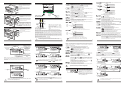
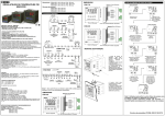
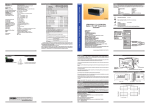
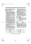
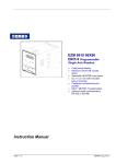
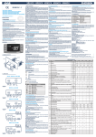
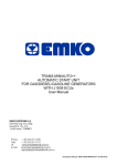
5. Failure Message in EPR-3790 Unit
Power Regulator
0
/
FG HI
/
U
V W
Z
/
00 00
/
1
0
0
0
Power Supply
100...240V V (- %15;+%10) 50/60Hz
24VV(-%15;+%10) 50/60Hz 24VZ(-%15;+%10)
Customer
E Output
4 Current Output (0/4...20mA Z)
5 Voltage Output (0/2...10V Z Max. 10mA)
All order information of EPR-3790
units are given on the table on the left. User
may form appropriate device configuration
from information and codes that on the
table and convert it to the ordering codes.
Firstly supply voltage, then other
specifications must be determined. Please
fill the order code blanks according to your
needs.
Please contact us, if your needs are
out of the standards.
6. Specifications
: Digital Power Regulator
: 77mm x 35mm x 62.5mm Plastic housing for panel
Mounting. Panel cut-out is 71x29mm.
Protection Class
: NEMA 4X (IP65 at front, IP20 at rear).
Weight
: Approximately 90Gr.
Environmental Rating
: Standard, indoor at an altitude of less than 2000 meters
with none-condensing humidity.
o
o
o
o
Storage / Operating Temperature: -40 C to +85 C / 0 C to +50 C
Storage / Operating Humidity
: 90 % max. (None condensing)
Installation
: Fixed Ýnstallation
Overvoltage Category
: II.
Pollution Degree
: II. Office or workplace, none conductive pollution
Operating Conditions
: Continuous
100-240 V V (-%15;+%10) 50/60 Hz. 2VA
Supply Voltage and Power
24V V (-%15;+%10) 50/60 Hz. 2VA
24VZ(-%15;+%10) 2W
Analogue Output
: 0/2...10VZ (Max.10mA) or
0/4...20mAZ
Analogue Output Accuracy
: ± % 0.1
Display
: 10 mm Red 4 digits LED Display
LED
: Run(Red), Error(Red), P(Red) 3 mm Led
c
V Symbol means Vac,
Z Symbol means Vdc,
Operating Temperature
: 0 to 50 °C
Max. Operating Humidity : 90% Rh (non-condensing)
Altitude
c
EPR-3790 77 x 35 DIN Size
Digital Power Regulator
Thank you very much for your preference to
use Emko Elektronik products, please visit our
Your Technology Partner web page to download detailed user manual.
www.emkoelektronik.com.tr
13
1.1 Environmental Ratings
: Up to 2000m.
Forbidden Conditions:
Corrosive atmosphere
Explosive atmosphere
Home applications (The unit is only for industrial applications)
1.2 General Specifications
Standard
- 4 Digits Display
- Easily adjustable set value from front panel
- Configurable display scale between -1999 and 9999
- Adjustable decimal point
- Set value low limit and set value high limit boundaries
- Adjustable ramp up and ramp down time
- Error Input
- 0/2...10V Z Voltage output or 0/4...20mAZ Current output
(It must be determined in order.)
- Password protection for programming and adjustment sections
EPR-3790 77x35 DIN Size
Device Type
Housing&Mounting
EPR-3790 series Digital Power Regulator devices are designed for controlling Analogue Input
TRIAC modules in industry. They can be used in many applications with their easy use and
ramped Start/Stop function.
EPR-3790
Universal Supply Input
100-240 V V (-%15;+%10)
50/60Hz
Power Supply
Input
Optional Supply Input
24 V W (-%15;+%10)
50/60Hz
Error Input
Digital Input
Digital Up
Digital Input
Digital Down
Digital Input
Standard
Analogue Output
(0/2...10VZ)
Analogue Input TRIAC
Module
Optional
Analogue Output
(0/4...20mAZ)
14
2
Instruction Manual. ENG EPR-3790 01 V03 03/14
1.3 Installation
c
2 General Description
Before beginning installation of this product, please read the instruction
manual and warnings below carefully.
In package ,
- One piece unit
- Two pieces mounting clamps
- One piece instruction manual
A visual inspection of this product for possible damage occured during shipment is
recommended before installation. It is your responsibility to ensure that qualified
mechanical and electrical technicians install this product.
If there is danger of serious accident resulting from a failure or defect in this unit, power
off the system and separate the electrical connection of the device from the system.
The unit is normally supplied without a power supply switch or a fuse. Use power switch
and fuse as required.
Be sure to use the rated power supply voltage to protect the unit against damage and to
prevent failure.
Keep the power off until all of the wiring is completed so that electric shock and trouble
with the unit can be prevented.
Never attempt to disassemble, modify or repair this unit. Tampering with the unit may
results in malfunction, electric shock or fire.
Do not use the unit in combustible or explosive gaseous atmospheres.
During the equipment is putted in hole on the metal panel while mechanical installation
some metal burrs can cause injury on hands, you must be careful.
Montage of the product on a system must be done with it’s fixing clamps. Do not do the
montage of the device with inappropriate fixing clamp. Be sure that device will not fall
while doing the montage.
It is your responsibility if this equipment is used in a manner not specified in this
instruction manual.
Mounting Clamp
Front Panel
IP65 protection
NEMA 4X
Panel surface
(maximum thickness 15mm / 0.59 inch)
2.1 Front View and Dimensions of EPR-3790 Unit
Max. 15 mm / 0.59 inch
EPR - 3790
RUN
P
%
Power Regulator
1.4 Warranty
4 mm /0.16 inch
77 mm / 3.03 inch
EMKO Elektronik warrants that the equipment delivered is free from defects in material and
workmanship. This warranty is provided for a period of two years. The warranty period starts from
the delivery date. This warranty is in force if duty and responsibilities which are determined in
warranty document and instruction manual performs by the customer completely.
2.2 Panel Cut-Out
110 mm / 4.33 inch (min)
1.5 Maintenance
Repairs should only be performed by trained and specialized personnel. Cut power to the device
before accessing internal parts.Do not clean the case with hydrocarbon-based solvents (Petrol,
Trichlorethylene etc.). Use of these solvents can reduce the mechanical reliability of the device.
Use a cloth dampened in ethyl alcohol or water to clean the external plastic case.
1.6 Manufacturer Company
Manufacturer Information:
Emko Elektronik Sanayi ve Ticaret A.Þ.
Demirtaþ Organize Sanayi Bölgesi Karanfil Sk. No:6 16369 BURSA/TURKEY
Phone : +90 224 261 1900
Fax
: +90 224 261 1912
Repair and maintenance service information:
Emko Elektronik Sanayi ve Ticaret A.Þ.
Demirtaþ Organize Sanayi Bölgesi Karanfil Sk. No:6 16369 BURSA/TURKEY
Phone : +90 224 261 1900
Fax
: +90 224 261 1912
15
16
58.5 mm / 2.30 inch
50 mm / 1.97 inch (min)
%
A
1
2
9
0
E
35 mm / 1.38 inch
P
EPR-3790 (77x35 DIN Size)
A BC D
29 mm / 1.14 inch
RUN
When Error input is activated , Error led starts
blinking after a period of time defined in
parameter . If the device is started, the Analog
output ramps down to minimum set limit.
After error input becomes passive error Led
turns off after a period of time defined in
parameter. (If Error latching is selected it turns
off when the decrement button is pressed on
the Operation Screen.) If the device is started,
the Analog output ramps up to maximum set
limit.
1.Preface
Power Regulator
EPR - 3790
7. Ordering Information
71 mm / 2.79 inch
3
4
3. Electrical Wiring Diagram
2.3 Panel Mounting
4.3. Program Parameters
Scale Low Limit Parameter ( Default = 0.0 )
It can be adjusted from -1999 to (
-1). At this value analogue output
becomes;
(2)
(1)
5.1. SET Parametresi
If
=0, according to the device type 0V Z or 0mA Z
(2)
(1)
If
=1, according to the device type 2V Z or 4mA Z
1
1-Before mounting the device in your
panel, make sure that the cut-out is of
the right size.
2-Insert the device through the cut-out.
If the mounting clamps are on the unit,
put out them before inserting the unit to
the panel.
GND
ERROR DOWN UP
1
2
3
4
5
6
7
8
0/2...10VZ OUTPUT
ca Y
P/N: EPR-3790 - 2.00.0.5/00.00/1.0.0.0
Scale High Limit Parameter:( Default = 100.0 )
It can be adjusted from (
+1) to 9999. At this value analogue output
becomes;
(1)
(2)
According to the device type10V Z or 20mA Z
9 10 11 12
2- Insert the mounting clamps to the
holes that located left and right sides of
the device and make the unit completely
immobile within the panel
2
c
Y
2
Note-2
=
Note-1 :There is an internal 33R W fusible
flameproof resistor in 100-240 V V 50/60Hz
There is an internal 4R7 W fusible flameproof
resistor in 24VW 50/60Hz
c
c
Led indication of
Displays Set Value Programming Mode is active
and Parameters
Led Indication
of Error
Led Indication
of Start
EPR - 3790
RUN
P
Change the SET value with
increment and decrement
buttons.
When Increment and Decrement
buttons are pressed, SET value is
shown on the display, and display
starts to blink
RUN
RUN
5 sec.
P
%
i
New Set value is shown on the display
Display stop blinking and operation
screen is shown
SET Value Screen
i
P
%
%
(1) It is valid, if the device type 0/2...10VZ analogue output.
(2) It is valid, if the device type 0/4...20mAZ analogue output.
Operation Screen
RUN
P
SET Value Screen
Operation Screen
RUN
5 sec.
%
RUN
P
RUN
%
P
%
if not pressed any button for 5
seconds, set value is saved.
Power Regulator
If there is an unexpected situation while opening the device, power off the
device and inform a qualified personnel.
7
Note-1: If programming section accessing password is
= 0, scale low limit
parameter screen
is observed instead of programming section accessing
Note-2: Parameters can be observed by pressing SET button in programming section
accessing screen without entering programming section accessing password. But
parameters can not be changed.
RUN
RUN
P
P
%
%
Password Entering Screen
Enter programming section
accessing password with
Increment and decrement buttons
Password Entering Screen
Press I/O button to submit the
password.
i
RUN
RUN
%
Display stop blinking and operation
screen is shown.
%
%
When Start/Stop button is pressed, Set value is
seen on display, Run led lights on, selected
analogue output starts to increase from the set
low limit value to set value during Tup(sec) time
with ramp.
While the device is running if Start/Stop button is
pressed again set low limit value is seen on
display, Run led lights off, analogue output starts
to decrease from set value to set low limit
value.during Tdown(sec) time.
If no operation is performed in Set value changing mode for 5 seconds, device turns
to operation screen automatically.
8
P
P
SET Value can be adjusted from minimum set value
parameter to maximum set value
parameter , they can be accessed from programming parameters.
Operation Screen is shown
Programming Section
Accessing Screen
Press increment
button for accessing
to the password
entering screen
When increment and decrement
buttons are pressed for 5 seconds,
”P” led starts to blink. If programming
section access password is set
Programming section access screen
is observed
4.4. Device Start/Stop Operation
Change the SET value with
increment and decrement
buttons.
When Increment and Decrement
buttons are pressed, SET value is
shown on the display, and display
starts to blink
Software
revision
number
%
RUN
RUN
%
RUN
P
Programming Section Accessing Password:( Default =0 )
It is used for entering to the programming section.
It can be adjusted from 0 to 9999. If this password is 0, programming section
can be accessed without entering the password.
P
P
Operation Screen
RUN
SET
4.2.2 Changing and Saving Set Value While The Device is not Running
Operation Screen
4.5 Entering To The Programming Mode, Changing and Saving Parameter
%
When pressing
button on
screen, adjustment value is seen on
screen. The value on the screen should be adjusted with Increment and
(1)
(2)
decrement button until 10.00V Z or 20.00mA Z is obtained from the
analogue output.
(1)
(2)
After getting the 10.00V Z or 20.00mAZ on analogue output, press
button for saving this value as an adjustment value
Ýf Set value is changed while the device is running, analogue output is affected
simultaneously by change on the set value. Analogue output increases or decreases
to the new set value according to the
and
parameters.
10
P
Adjustment Value Parameter:
Adjustment value for Analogue output. It can be adjusted from 0 to 4095.
%
if no button is pressed for 5
seconds, set value is saved.
EPR - 3790
c
(1) It is valid, if the device type 0/2...10VZ analogue output.
(2) It is valid, if the device type 0/4...20mAZ analogue output.
Button Protection Parameter: ( Default =0 )
Buttons protection is passived.
Start-Stop Button protection is actived.
Adjustment Section Accessing Password:
Required password is entered via this parameter for accessing to the
adjustment section. If the parameter value is entered as 3083,
screen
is accessed, otherwise
parameter is seen
Operation Screen
RUN
EPR - 3790
Error Input Passive on Delay Parameter :( Default = 0 )
When the error input is passive ,this parameter indicates the delay time for the
device to leave the error mode.When this parameter is 9998,if the increment
button is pressed
is observed and error latching is selected.The device
stays in error mode even if error condition is disappared.In order to make Error
latching passive the decrement button must be pressed in Main Operation
Screen.It can be adjusted from 0 to 9999 seconds.
0V(1)/ 0mA(2)
Analogue Output Range Selection Parameter:( Default = 0 )
Analogue output range is determined with this parameter
(1)
(2)
according to the device type 0...10V Z or 0...20mA Z
(1)
(2)
according to the device type 2...10V Z or 4...20mA Z
%
%
4.1 Observation of Software Revision on the Display
“ rv” ÞRevision
(2)
/ Su-L mA
9
P
P
Note-1: If increment or decrement button is pressed for 2 seconds continuously, increment and
decrement number become 10, if pressed for 4 seconds continuously, increment and decrement
number become 100, if pressed for 6 seconds continuously, increment and decrement number
become 1000.
Power Regulator
Error Input Active on Delay Parameter :( Default = 0 )
When the error input is active ,this parameter indicates the delay time for the
device to be in error mode.It can be adjusted from 0 to 9999 seconds.
Figure-4.2 Power On Behaviour (Strt=1)
RUN
RUN
SET Value Screen
When power is first applied to the Digital Power Regulator, software revision number is shown on
the display.
Device starts to operate, Analogue output is equal to the Set value.
OFF
Power Regulator
It is used as Start /Stop
Button and also
It is used to enter the
It is used as Enter
programming and set value button in programming
changing modes as well as
mode.
decrementation
Set Changing Value Parameter:( Default = 4 )
Changing value for Set value is determined with this parameter.
Set changing value become one(1)
Set changing value become ten(10)
Set changing value become hundred(100), for each pressing the
Increment, Decrement button
Set changing value become incremental. (Note-1)
Note-1 : If increment or decrement button is pressed for 2 seconds continuously, increment
and decrement number become 10, if pressed for 4 seconds continuously, increment and
decrement number become 100, if pressed for 6 seconds continuously, increment and
decrement number become 1000.
SET Value Screen
Operation Screen
%
Ramp Up Time Parameter:( Default = 10sec )
(1)
(1)
Increasing time of the analogue output from 0V Z value to 10V Z value or
(2)
(2)
from 0mA Z value to 20mA Z value is determined with this parameter.
It can be adjusted from 0 to 6000.
Soak Time Parameter:( Default = 0 sec )
Soak time is activeted unless soak parameter is entered 0. After
ramp
time is up,the output remains active for soak time and output returns to 0. It
can be selected between 0 and 6000.
Ramp Down Time Parameter:( Default = 10sec )
(1)
(1)
Decreasing time of the analogue output from 10V Z value to 0V Z value or
(2)
(2)
from 20mA Z value to 0mA Z value is determined with this parameter.
It can be adjusted from 0 to 6000.
(2)
6
4.2.1 Changing and Saving Set Value Device is Running
(Set - LoL)X rut
(sec)
(uPL - LoL)
Counts in Minute
POWER
i
2V(1)/ 4mA(2)
0V(1)/ 0mA(2)
Counts in Second
POWER ON
The instrument is protected with an internal fuse (Please refer to Note-1 for information). In
case of failure it is suggested to return the instrument to the manufacturer for repair.
4.2 Changing and Saving Set Value
Note-1
It is used to enter the
programming and set
value changing modes
as well as
incrementation and
accessing to the
parameters in
programming mode.
value to Scale high
0V(1)/ 0mA(2)
Su-L V
T up
(2)
Figure-4.3 Power On Behaviour (Strt=2)
Time Unit Selection Parameter:( Default =0 )
ON
ANALOGUE
OUTPUT
(1)
T up =
Su-L V / Su-L mA
(1)
0V(1)/ 0mA(2)
value to Set high
Figure-4.1 Power On Behaviour (Strt=0)
=
T up
(2)
Set V / Set mA
OFF
(1)
ANALOGUE
OUTPUT
Note-2: “L” is (+), “N” is (-) for 24V Z Supply
Voltage
Note-3: External Fuse is recommended
5
4. Front
Ön Panelin
PanelTanýmý
Definition
ve Menülere
and Accessing
Eriþimto the Menus
=
ON
There is no power supply switch or fuse on the device. So a power supply switch and a fuse must be added
to the supply voltage input. Power supply switch and fuse must be put to a place where user can reach
easily. Power supply switch must be two poled for seperating phase and neutral. On/Off condition of power
supply switch is very important in electrical connection. On/Off condition of power supply switch must be
signed for preventing the wrong connection.
External fuse must be on phase connection in Vsupply input.
External fuse must be on (+) line connection in Zsupply input.
2
For
POWER ON
Make sure that the power supply voltage is same indicated on the instrument. Switch on the power supply
only after that all the electrical connection have been completed. Supply voltage range must be determined
in order. While installing the unit, supply voltage range must be controlled and appropriate supply voltage
must be applied to the unit. Controlling prevents damages in unit and system and possible accidents as a
result of incorrect supply voltage.
1
ANALOGUE
OUTPUT
Device does not start to operate, Analogue output is equal to the Set low limit
POWER
(1)
Set V / Set mA
value.
External
Fuse
(1 A T)
POWER ON
OFF
=
Power On Output Control Parameter: ( Default = 2)
When power on firstly, Analogue and digital outputs status can be determined
with this parameter. It can be adjusted from 0 to 2.
Supply Voltage
100...240V V (- %15;+%10) 50/60Hz 2VA or
24VV(-%15;+%10) 50/60Hz 2VA or
24VZ(-%15;+%10) 2W
2-Pull the unit through the front side of
the panel
For
Decimal Point Position Parameter:( Default =1)
Decimal point position is determined with this parameter. It can be adjusted
from 0 to 3.
aL
N
1
Power
Supply
Switch
2.5 Removing from the Panel
1-Pull mounting clamps from left and
right fixing sockets.
Analogue Output
(0/2...10V Z ) or
(0/4...20mAZ )
3.1 Supply Voltage Input Connection of the Device
Montage of the unit to a system must be
done with it’s own fixing clamps. Do not
do the montage of the device with
inappropriate fixing clamps. Be sure
that device will not fall while doing the
montage.
Loosen the screws
Set High Limit Parameter:( Default = 100.0)
Set value can not be defined greater than this value.
It can be adjusted from Set low limit parameter
limit parameter
value.
Note-1
1-Insert the unit in the panel cut-out from
the front side.
Supply Voltage Input
100...240V V (- %15;+%10) 50/60Hz 2VA
24VV(-%15;+%10) 50/60Hz 2VA
24VZ(-%15;+%10) 2W
Note-3
The unit is designed for panel mounting.
1
Digital Up
Digital Down
Error Input
2.4 Installation Fixing Clamp
ON
POWER
ANALOGUE
OUTPUT
Set Low Limit Parameter:( Default = 0.0 )
Set value can not be defined less than this value.
It can be adjusted from Scale low limit parameter
limit parameter
value.
N(-) L(+)
2
=
Device starts to operate, Analogue output is increased from the Scale Set
low limit to Set value according to the ramp up time.
Scale Low Limit Parameter
Scale Low Limit Parameter Value
Change the parameter value
Parameter value is accessed by pressing
with
increment and decrement
increment button. If set button is pressed,
buttons
next parameter is shown.
RUN
P
%
Scale Low Limit Parameter Value
Press I/O button for saving the
parameter value
i
11
If no operation is performed in programming mode for 20 seconds, device turns to
main operation screen automatically.
12