1
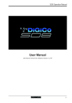
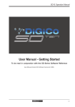
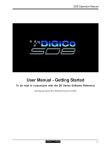
Appendix 1 - OVERDRIVE Operation
SD8 Operation Manual
Appendix 1:
Overdrive Operation
For Software Versions 2.0.160+
A1-1
Appendix 1 - OVERDRIVE Operation
Contents
A1.1 Overview ................................................................................ .......A1-3
A1.2 New Features ......................................................................... .......A1-3
A1.2.1 New Stealth FPGA Effects ...................................... .......A1-3
A1.2.2 LCR Master Buss .................................................... .......A1-4
A1.2.3 Snapshot Scopes and Crossfades ........................ .......A1-4
A1.2.4 Custom Banks ......................................................... .......A1-5
A1.2.5 Dynamic EQ ............................................................. .......A1-6
A1.2.6 Multi-Band Dynamics ............................................. .......A1-7
A1.2.7 Global Set To Defaults ............................................ .......A1-8
A1.2.8 Security .................................................................... .......A1-8
A1.2.8 Talk To Auxes .......................................................... .......A1-9
A1.2.9 Audio I/O Ports ...................................................... .......A1-10
A1.2.10 Session Report ................................................... .......A1-10
A1.2.11 Options Menu ...................................................... .......A1-10
A1.2.12 Snapshots & MTC/SONY 9PIN ............................ .......A1-11
A1.2.13 Additional New Features ..................................... .......A1-11
A1-2
Appendix 1 - OVERDRIVE Operation
A1.1 Overview
This Appendix should be read in conjunction with the standard SD8 User Manual.
It contains details of additional new features added to SD8 software versions 2.0.160+ (Overdrive)
IMPORTANT NOTE : If you are loading sessions from older versions of SD8 software, some of the extra new functions such as
additional Graphic EQ's and new Effects will not appear in your session until you restructure your session. You do not need to
clear channels, rebuild banks, or make any other changes : It is the act of restructuring (Files Menu – Session Structure –
Restructure) that adds the additional resources to your session.
A1.2 New Features
A1.2.1 New Stealth FPGA Effects ................................................
Internal FX have been increased from 6 to 8. The new effects are the same effects found on the SD7, and the FX rack can be built using
any 8 of the effects, in any combination. This allows users to have 8 delays, 8 reverbs, or any other combination of the available effects.
The total number of other Effects which can be used simultaneously is dependent on combinations selected and limited by total resources.
The effects are arranged in groups. Press an FX PRESET button on any existing effect or press the NEW button in the top left of the
Effects panel to view available effects. Effects groups are listed in the left section of the effects presets panel. Press a Group name to
view the selections available on the right of the panel. Press the effects name buttons to select, change or remove effects, in the same
way as on channel screens.
NOTE: When Effects names are greyed out, the maximum number of available effects has been reached.
Old Effects have been removed from SD8 (and will be removed from loaded sessions). The conversion from old to new FX presets
necessitated removing all presets prior to loading an old session, thus current presets which are not in the file are not preserved as they
would be normally.
When a preset is selected the effect is created and displayed without any signal or routing. Signals can be routed to and from the effect
using standard input/output routing panels. It is still possible to create & route FX using the FX Output Button found at the output of each
channel type.
NOTE : All Effects created directly in the FX Rack are stereo. Mono effects can only be created using the FX Output button found on
channels.
A1-3
Appendix 1 - OVERDRIVE Operation
A1.2.2 LCR Master Buss ...............................................................
It is now possible to build, or restructure, a session to include an LCR Master buss.
If an LCR Buss exists within the session, it is automatically assumed to be the Master buss, and the dedicated Master fader is automatically assigned to the LCR buss.
When a channel is routed to the LCR Master, the centre component of the signal can be adjusted. This is the Blend control found on every
input channel, and is a 2nd Function of the Pan Control.
The Blend control varies the amount of signal sent to the Centre leg of the LCR buss. When adjusted to LR (fully anti-clockwise), a centre
panned signal only goes to the L & R components of the LCR buss. When adjusted to LCR (fully clockwise), a centre panned signal only
goes to the C component of the LCR buss. Adjustments between these two extremes varies the ratio of L/R and C levels.
A1.2.3 Snapshot Scopes and Crossfades ..................................
The snapshot recall scope and crossfade settings have been expanded to allow per channel settings.
Open the Snapshot Panel, and expand the scopes section. Both the per-snapshot recall scope, and the crossfade settings panels can be
expanded to allow per-channel settings.
A1-4
Appendix 1 - OVERDRIVE Operation
A1.2.4 Custom Banks ....................................................................
Custom Banks can now be created, allowing users to build mixed banks containing Input, Output and CG Channels.
The assigning of faders to a bank is a worksurface LCD function. The LCD Function also provides the unassign function to remove
channels from a fader bank.
Press LCD Function, then Assign. Select the fader, or faders, to be assigned. On the Master screen, open the Channel list from the
Layout Menu. Touch the channel to be assigned.
If more than one fader was placed in assign mode, then touching a channel in the Channel List Panel selects the first channel to be
assigned, and consecutive channels are assigned to the faders in assign mode.
NOTE : If a channel exists in only one place on the worksurface, and is subsequently removed (unassigned), it will continue to pass audio
in whatever state it was left. You will have no control over that channel until it is reassigned to the worksurface.
Press LCD Function button
then Assign Faders
Press LCD button(s)
for Assignment
Open
Layout/Channel List
Click down arrow
to expand list
Touch first channel
to assign
A1-5
Appendix 1 - OVERDRIVE Operation
A1.2.5 Dynamic EQ .......................................................................
Up to 8 Channels can have their EQ modules switched into Dynamic EQ mode
On any channel (Input or Output), open the EQ Module, and expand the dynamic controls. You can then switch on any (or all) or the
dynamic controls for that EQ Module.
Only 8 Channels can have their EQ Modules placed in Dynamic mode. An warning message will appear on screen if an attempt is made to
use Dynamic EQ on more than 8 channels.
Dynamic EQ Details
In a dynamic EQ module, the EQ adjustment is applied dynamically, based on the level of the incoming frequency relative to a predetermined threshold.
DiGiCo dynamic EQ can operate in two modes.. over or under.
Over Mode
To place the dynamic module into Over mode, ensure that the Over indication below the threshold control is not illuminated.
When the signal entering the module passes the threshold, the EQ adjustment (as determined by the frequency and Q controls) starts to
be applied, up to a maximum adjustment, determined by the EQ band gain control. The manner in which the EQ adjustment is applied
once the threshold has been reached is determined by the attack, release and ratio controls.
Gain : Sets the maximum EQ adjustment that could be applied
Frequency / Q / Curve : Adjusts the EQ characteristics
Threshold : Sets the threshold at which the EQ starts to be applied
Attack : controls how quickly the dynamic module responds to level passing the threshold
Release : adjusts how quickly the module responds to a fall in level
Ratio : controls how quickly the maximum adjustment is reached once the threshold level is passed.
A1-6
Appendix 1 - OVERDRIVE Operation
Over Mode is generally used with a reduction in gain at a specific frequency, such that when the threshold is reached, a gradual reduction
of level at that frequency is applied. This could be used to control a change in tonal characteristics as a singer pushes their voice to sing
louder.
Under Mode
To place the dynamic module into Under mode, ensure that the Over indication below the threshold control is illuminated.
In under mode, the maximum EQ adjustment (as determined by the frequency, Q and band gain controls) is applied when the signal
entering the module is below the threshold. As the signal level approaches the threshold, the EQ adjustment is reduced to the point where
there is no EQ being applied at the threshold. The manner in which the EQ adjustment is reduced as the signal level approaches the
threshold is determined by the attack, release and ratio controls.
A1.2.6 Multi-Band Dynamics ........................................................
Up to 8 Channels can have their Dynamics (Compressor) modules switched into Multi-band mode
On any channel (Input or Output), open the Dynamics Module, and expand the dynamic controls using the multi-band button.
Only 8 Channels can have their Compressor modules placed in Multi-band mode. An warning message will appear on screen if an attempt
is made to use Multi-band dynamics on more than 8 channels.
Each band includes all of the parameters as those found in the single band compressor. The link function remains available for the whole
compressor, and is not assigned to any band. The bands can be switched on individually using the on buttons in the left-hand side of each
band, or together using the all on button to the display’s right.
Note: When any band is switched Off, that Band will not pass audio.
The crossover frequency between bands is controlled using the purple and red pots to the left of the hi and lo bands. Each crossover has
a range of 20Hz to 20kHz, and the crossover frequencies are displayed below each pot. Each band can be auditioned by pressing the
listen button below each gain pot which solo’s that band to the mix (not the solo buss), in effect temporarily switching off the other bands.
Pressing multi-band again returns the compressor to single-band.
The channel strip’s compressor threshold and gain controls adjustment all three bands’ controls, maintaining any relative offsets. The
individual controls are mapped to the assignable rotaries below the screen.
Note: Beyond the link function, the single and multi-band compressors have completely separate settings: No settings are copied between
them, and the settings of each remain unchanged when the other is active. Note also, however, that multi-band and single band dynamics
cannot both be active on one channel at the same time.
A1-7
Appendix 1 - OVERDRIVE Operation
A1.2.7 Global Set To Defaults ......................................................
The Global Set to Defaults Panel allows global settings to be applied to the console.
Open the Global Set to Defaults Panel from the Files Menu. Select the Channel type from the list on the left side of the panel, and then
select the operation to perform from the available functions.
An undo function is provided which undoes all changes since the panel was opened. Once the Global Default Panel is closed, changes
cannot be undone.
A1.2.8 Security...............................................................................
Security modes are now implemented in the system menu, with a choice of three modes of operation :
Setup : Users have full access to every function on the console.
Live : Access to elements of the console can be limited, and password protected.
Unattended : The console is locked, and cannot be operated.
User passwords can be defined for the Live and Unattended modes. To set a password, press the Set Password button. Enter the old
password, then enter the new password twice.
By default, the passwords are blank.
NOTE: If you should forget your password, call your Distributor to obtain a reset password. Entering the master override password will
delete all of the user-set passwords, allowing new passwords to be set.
A1-8
Appendix 1 - OVERDRIVE Operation
To modify restrictions in Live mode, press the Set Live Restrictions button in the Security Panel. A range of options are provided, and the
channel list can be expanded with a scope per controller, per channel.
A Tick indicates access allowed. A Cross indicates the item will be locked when the console is place in Live mode.
A1.2.8 Talk To Auxes ....................................................................
Talk to Aux features have been added – a new assignable row on Aux Outputs, controllable independently or from the Talkback panel
which has a new Talk to Aux select list for each Talk button. This is implemented as a new Talkback Input channel type which uses a
single engine processing channel to provide the aux sends. This new channel appears in a bank on its own for new sessions; when
loading old sessions it is created automatically but not assigned to a bank.
On the Aux Output channels hold one of the Assign buttons next to the rows of assignable controls and then touch the talk section on
screen. This will assign the selected rotary control and switch to be Talk Level and Talk On/Off.
Worksurface Talk A and B buttons can be programmed to activate the Talk function on single or multiple user defined channels.
Open the Setup/Talkback panel and touch the label above the a or b Talk buttons, then select any combination of Mono and Stereo
Auxes to activate with that button.
A1-9
Appendix 1 - OVERDRIVE Operation
A1.2.9 Audio I/O Ports ..................................................................
A maximum of 2 Optocore ports are now available for the SD8 as a hardware modification. This is in addition to the two existing MADI
ports - please contact your distributor for details.
On the Audio I/O panel, it is now possible to change the Connection for racks 1 to 4, and freely assign any MADI or Optocore connection
to any rack.
A1.2.10 Session Report ................................................................
A Session Report button has been added under Files menu. This lists the session details on the master screen in an RTF compatible
format. The Save File button at the top left of this panel will save the report as the session filename suffixed with .rtf.
A1.2.11 Options Menu...................................................................
Additional User Options Include :
Surface Tab
Round to Whole dB’s : All fractional dB readouts are rounded to the nearest integer value
Auto-Cancel 2nd Function : Automatically cancels the 2nd Function after he predetermined time. Adjusts 1 – 15 seconds
Faders Tab
0dB Detent : Switches the electronic 0dB detent on or off. Now available on All channels, just Graphic EQ’s, or None.
Fader Mode : Switches faders between Free and Protected modes. In protected mode, fader must recognize a touch before it allows
movement.
A1-10
Appendix 1 - OVERDRIVE Operation
Disable Tab
The following worksurface buttons can be disabled. It does not affect on-screen operation of the functions
Snapshot Previous / Next
Snapshot Auto Update
Joystick
Hard Mute
Alt Input
Meters Tab
Overview Meters : Choice of Large or Small, independently for Input and Output Meters
Session Tab
Default Positions at Next Startup : If set to YES, then all window positions will be reset to default positions at next launch.
A1.2.12 Snapshots & MTC/SONY 9PIN ........................................
Snapshots can now be programmed to send MMC messages, allowing control of external playback devices.
Within the snapshot scope section, the Transport Control button is now enabled. This opens the Snapshot Transport Control panel.
The panel lists all current session snapshots and allows entry, per snapshot, of the following MMC commands.
PLAY : Basic Play command. External device will play from current location
PLAY FROM : External device will play from specified time value
PLAY TO : External device will stop when the specified time is reached.
LOCATE TO : External device will Locate to specified time.
STOP : Basic Stop command. External device will stop.
Commands can be sent via MIDI or 9Pin, selected at the bottom of this panel.
NOTE : Correct MMC operation relies on a correctly configured MIDI system, with MTC from the external device connected to the console
MIDI Input. If this MTC connection is not present, the MMC snapshot system will not work.
A Transport Control panel is also provided in the Layout Menu. This provides a MTC readout of incoming MTC, and allows direct control
of the external device.
It is now possible to program snapshots to fire at specific MTC Values.
Open the Snapshots Recall Times Panel. For each snapshot, enter an MTC value in the “Recall at” column. This functionality can be
switched on / off per snapshot by setting the tick in the Active column to the right of the Recall at column.
A1.2.13 Additional New Features .................................................
The Matrix has been expanded to include 16 inputs (Previously 12).
There are now 24 Graphic EQ’s (Previously 12)
A1-11